Page 1123 of 1784
(13) Remove output shaft fifth gear snap ring with
two screwdrivers (Fig. 37).
(14) Press fifth gear, rear bearing, first gear and
inner race off output shaft (Fig. 38).(15) Remove needle roller bearing.
(16) Remove synchronizer ring.
(17) Remove synchronizer lock ball with pencil
magnet (Fig. 39).
(18) Press 1-2 synchronizer and second gear off
output shaft (Fig. 40).
(19) Remove needle roller bearing from the shaft
or second gear.
Fig. 37 Removing Fifth Gear Snap Ring
Fig. 38 Removing Fifth Gear And First Gear Bearing
And Race
Fig. 39 Synchronizer Lock Ball Removal
Fig. 40 1-2 Synchronizer And Second Gear Removal
21 - 12 AX 4/5 MANUAL TRANSMISSIONJ
Page 1124 of 1784

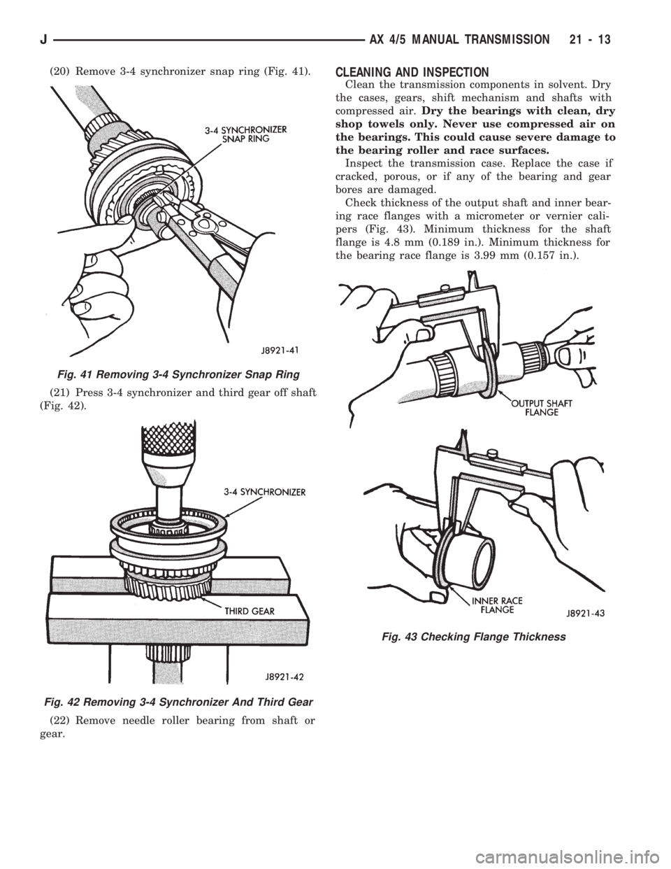
(20) Remove 3-4 synchronizer snap ring (Fig. 41).
(21) Press 3-4 synchronizer and third gear off shaft
(Fig. 42).
(22) Remove needle roller bearing from shaft or
gear.CLEANING AND INSPECTION
Clean the transmission components in solvent. Dry
the cases, gears, shift mechanism and shafts with
compressed air.Dry the bearings with clean, dry
shop towels only. Never use compressed air on
the bearings. This could cause severe damage to
the bearing roller and race surfaces.
Inspect the transmission case. Replace the case if
cracked, porous, or if any of the bearing and gear
bores are damaged.
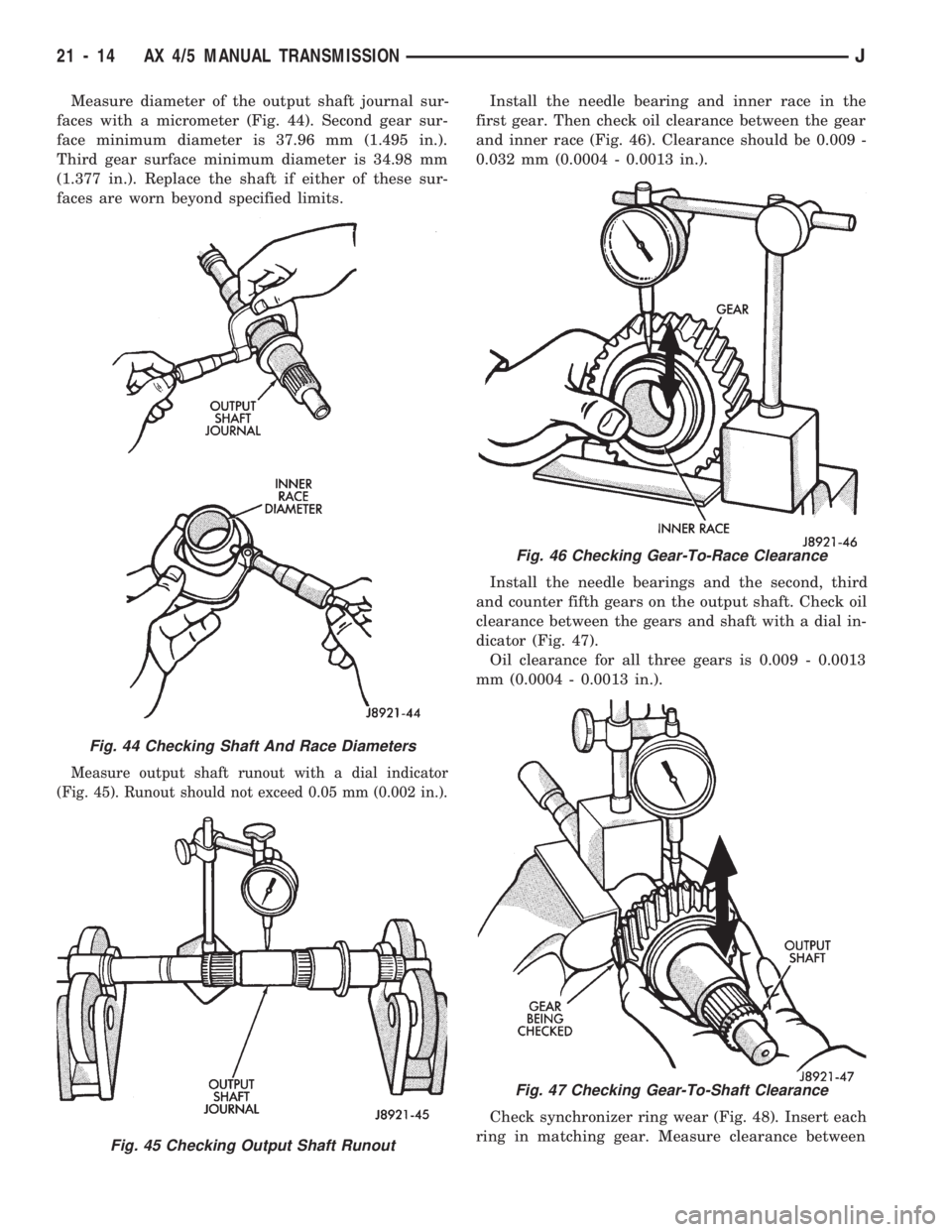
Check thickness of the output shaft and inner bear-
ing race flanges with a micrometer or vernier cali-
pers (Fig. 43). Minimum thickness for the shaft
flange is 4.8 mm (0.189 in.). Minimum thickness for
the bearing race flange is 3.99 mm (0.157 in.).
Fig. 41 Removing 3-4 Synchronizer Snap Ring
Fig. 42 Removing 3-4 Synchronizer And Third Gear
Fig. 43 Checking Flange Thickness
JAX 4/5 MANUAL TRANSMISSION 21 - 13
Page 1125 of 1784

Measure diameter of the output shaft journal sur-
faces with a micrometer (Fig. 44). Second gear sur-
face minimum diameter is 37.96 mm (1.495 in.).
Third gear surface minimum diameter is 34.98 mm
(1.377 in.). Replace the shaft if either of these sur-
faces are worn beyond specified limits.
Measure output shaft runout with a dial indicator
(Fig. 45). Runout should not exceed 0.05 mm (0.002 in.).
Install the needle bearing and inner race in the
first gear. Then check oil clearance between the gear
and inner race (Fig. 46). Clearance should be 0.009 -
0.032 mm (0.0004 - 0.0013 in.).
Install the needle bearings and the second, third
and counter fifth gears on the output shaft. Check oil
clearance between the gears and shaft with a dial in-
dicator (Fig. 47).
Oil clearance for all three gears is 0.009 - 0.0013
mm (0.0004 - 0.0013 in.).
Check synchronizer ring wear (Fig. 48). Insert each
ring in matching gear. Measure clearance between
Fig. 44 Checking Shaft And Race Diameters
Fig. 45 Checking Output Shaft Runout
Fig. 46 Checking Gear-To-Race Clearance
Fig. 47 Checking Gear-To-Shaft Clearance
21 - 14 AX 4/5 MANUAL TRANSMISSIONJ
Page 1126 of 1784
each ring and gear with feeler gauge. Replace ring if
clearance exceeds 2.0 mm (0.078 in.).
Check shift fork-to-synchronizer hub clearance
with a feeler gauge (Fig. 49). Replace the fork if
clearance exceeds 1.0 mm (0.039 in.).
TRANSMISSION ASSEMBLY AND ADJUSTMENT
Lubricate the transmission components with Mopar
75W-90, GL 5 gear lubricant during assembly. Use
petroleum jelly to lubricate seal lips and/or hold
parts in place during installation. Refer to the
Counter Gear Comparison Chart (Fig. 102) during
assembly for AX 4/5 gear differences.
ASSEMBLING OUTPUT SHAFT, INPUT SHAFT
AND COUNTER GEAR
(1) If front bearing was removed from input shaft,
press new bearing on shaft (Fig. 50).
Fig. 50 Installing Front Bearing And Snap Ring
Fig. 48 Checking Synchronizer Ring Wear
Fig. 49 Checking Fork-To-Hub Clearance
JAX 4/5 MANUAL TRANSMISSION 21 - 15
Page 1127 of 1784
(2) Secure front bearing with thickest snap ring
that will fit in groove (Fig. 50).
(3) Press front bearing on counter gear. Secure
bearing with thickest snap ring that will fit in ring
groove (Fig. 51).
(4) Install new oil seals in front bearing retainer
and adapter (Fig. 52). Bearing retainer seal depth is
11.2 - 12.1 mm (0.441 - 0.480 in.).(5) Install reverse shaft and shaft retaining pin in
adapter. Then install access hole plug with torx bit
(Fig. 53).
(6) Lubricate transmission components with speci-
fied gear lubricant.
(7) Assemble 1-2 and 3-4 synchronizer hubs,
sleeves, springs and key inserts (Fig. 54).
Fig. 51 Installing Counter Gear Front Bearing And Snap Ring
Fig. 52 Oil Seal Installation
Fig. 53 Installing Reverse Shaft Pin
Fig. 54 Synchronizer Identification
21 - 16 AX 4/5 MANUAL TRANSMISSIONJ
Page 1128 of 1784
(8) Assemble and install third gear, needle bear-
ing, synchronizer ring, 3-4 synchronizer and snap
ring on output shaft (Fig. 55). Use thickest snap ring
that fits in shaft groove.
(9) Verify third gear thrust clearance with feeler
gauge (Fig. 56). Clearance should be 0.10 - 0.25 mm
(0.004 - 0.010 in.).(10) Assemble second gear, gear needle bearing,
synchronizer ring and 1-2 synchronizer. Then press
assembly on output shaft (Fig. 57).
(11) Install first gear lock ball in output shaft (Fig.
58).
Fig. 55 Installing Third Gear And 3-4 Synchronizer
Fig. 56 Checking Third Gear Clearance
Fig. 57 Installing Second Gear And Synchronizer
Fig. 58 Installing First Gear And Lock Ball
JAX 4/5 MANUAL TRANSMISSION 21 - 17
Page 1129 of 1784
(12) Assemble first gear, synchronizer ring, gear
needle bearing and inner race (Fig. 59). Then install
assembly on output shaft.Rotate inner race until
aligned with locking ball.
(13) Press rear bearing on shaft (Fig. 59). Snap
ring groove in bearing goes toward rear. Use screw-
driver to hold inner race in position when installing
bearing (Fig. 60).
(14) Install snap ring on rear bearing.(15) Check first-second gear thrust clearance (Fig.
61). Standard clearance is 0.10 - 0.25 mm (0.004 -
0.010 in.).
(16) Press fifth gear on output shaft (Fig. 62).
(17) Install fifth gear snap ring (Fig. 63). Use
thickest snap ring that will fit in shaft groove.
Fig. 59 First Gear Assembly
Fig. 60 Installing Output Shaft Rear Bearing
Fig. 61 Checking First-Second Gear Clearance
Fig. 62 Installing Output Shaft Fifth Gear
21 - 18 AX 4/5 MANUAL TRANSMISSIONJ
Page 1130 of 1784
(18) Lubricate input shaft roller bearings with pe-
troleum jelly and install rollers in shaft (Fig. 64).
(19) Install output shaft assembly in intermediate
plate (Fig. 65). Tap plate with mallet and pull on
shaft to seat assembly.
Fig. 63 Selecting/Installing Fifth Gear Snap Ring
Fig. 64 Installing Input Shaft Bearing Rollers
Fig. 65 Installing Output Shaft In Intermediate Plate
JAX 4/5 MANUAL TRANSMISSION 21 - 19