1994 JEEP CHEROKEE transmission
[x] Cancel search: transmissionPage 1030 of 1784
ADJUSTMENTÐXJ FRONT SHAFT
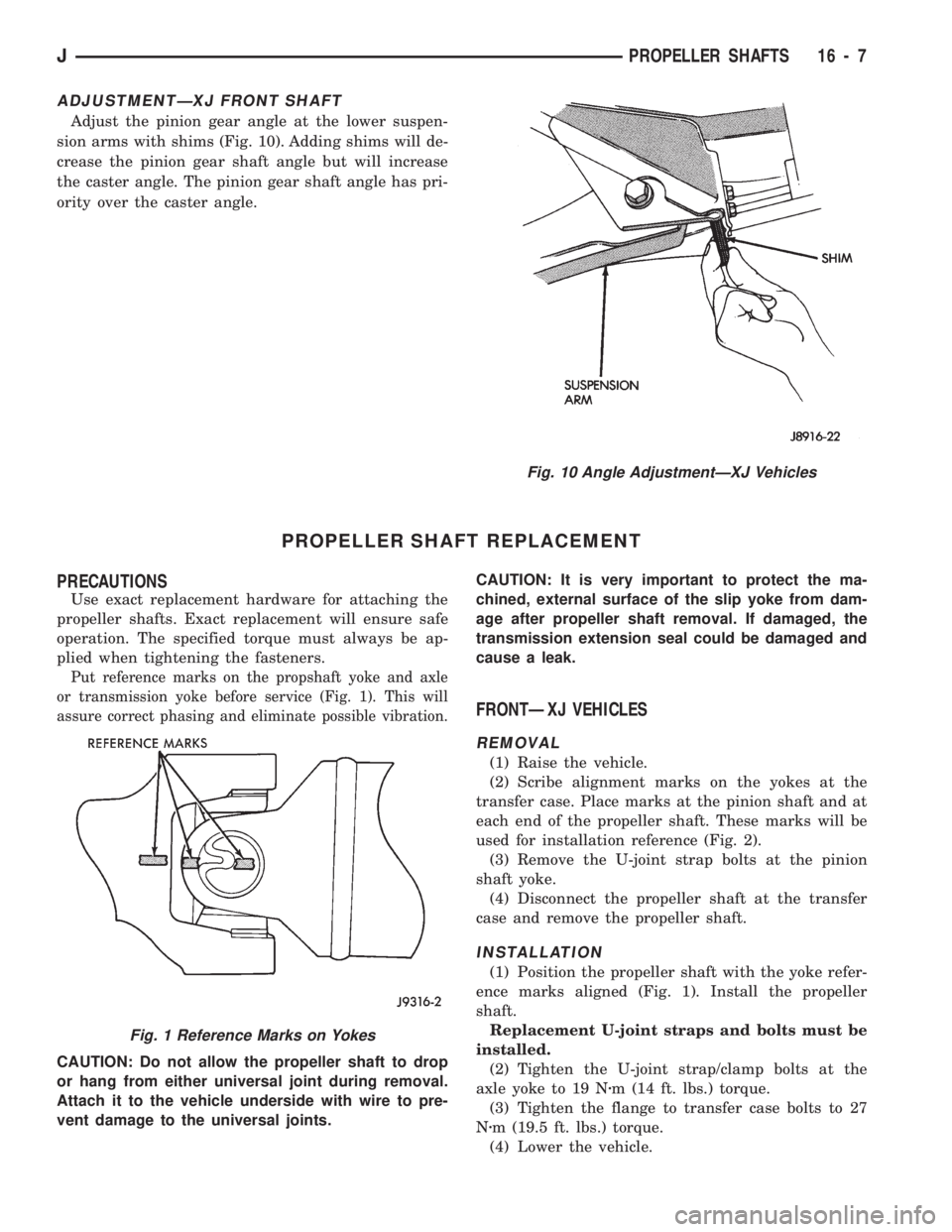
Adjust the pinion gear angle at the lower suspen-
sion arms with shims (Fig. 10). Adding shims will de-
crease the pinion gear shaft angle but will increase
the caster angle. The pinion gear shaft angle has pri-
ority over the caster angle.
PROPELLER SHAFT REPLACEMENT
PRECAUTIONS
Use exact replacement hardware for attaching the
propeller shafts. Exact replacement will ensure safe
operation. The specified torque must always be ap-
plied when tightening the fasteners.
Put reference marks on the propshaft yoke and axle
or transmission yoke before service (Fig. 1). This will
assure correct phasing and eliminate possible vibration.
CAUTION: Do not allow the propeller shaft to drop
or hang from either universal joint during removal.
Attach it to the vehicle underside with wire to pre-
vent damage to the universal joints.CAUTION: It is very important to protect the ma-
chined, external surface of the slip yoke from dam-
age after propeller shaft removal. If damaged, the
transmission extension seal could be damaged and
cause a leak.
FRONTÐXJ VEHICLES
REMOVAL
(1) Raise the vehicle.
(2) Scribe alignment marks on the yokes at the
transfer case. Place marks at the pinion shaft and at
each end of the propeller shaft. These marks will be
used for installation reference (Fig. 2).
(3) Remove the U-joint strap bolts at the pinion
shaft yoke.
(4) Disconnect the propeller shaft at the transfer
case and remove the propeller shaft.
INSTALLATION
(1) Position the propeller shaft with the yoke refer-
ence marks aligned (Fig. 1). Install the propeller
shaft.
Replacement U-joint straps and bolts must be
installed.
(2) Tighten the U-joint strap/clamp bolts at the
axle yoke to 19 Nzm (14 ft. lbs.) torque.
(3) Tighten the flange to transfer case bolts to 27
Nzm (19.5 ft. lbs.) torque.
(4) Lower the vehicle.
Fig. 10 Angle AdjustmentÐXJ Vehicles
Fig. 1 Reference Marks on Yokes
JPROPELLER SHAFTS 16 - 7
Page 1031 of 1784
REARÐXJ,YJ VEHICLES
REMOVAL
(1) Shift the transmission and transfer case (if ap-
plicable) to their Neutral positions. Raise the vehicle.
(2) Scribe alignment marks at the pinion shaft and
at each end of the propeller shaft. These marks will
be used for installation reference.
(3) Remove the U-joint strap bolts at the pinion
shaft yoke.
(4) Slide the slip yoke off of the transmission/
transfer case output shaft and remove the propeller
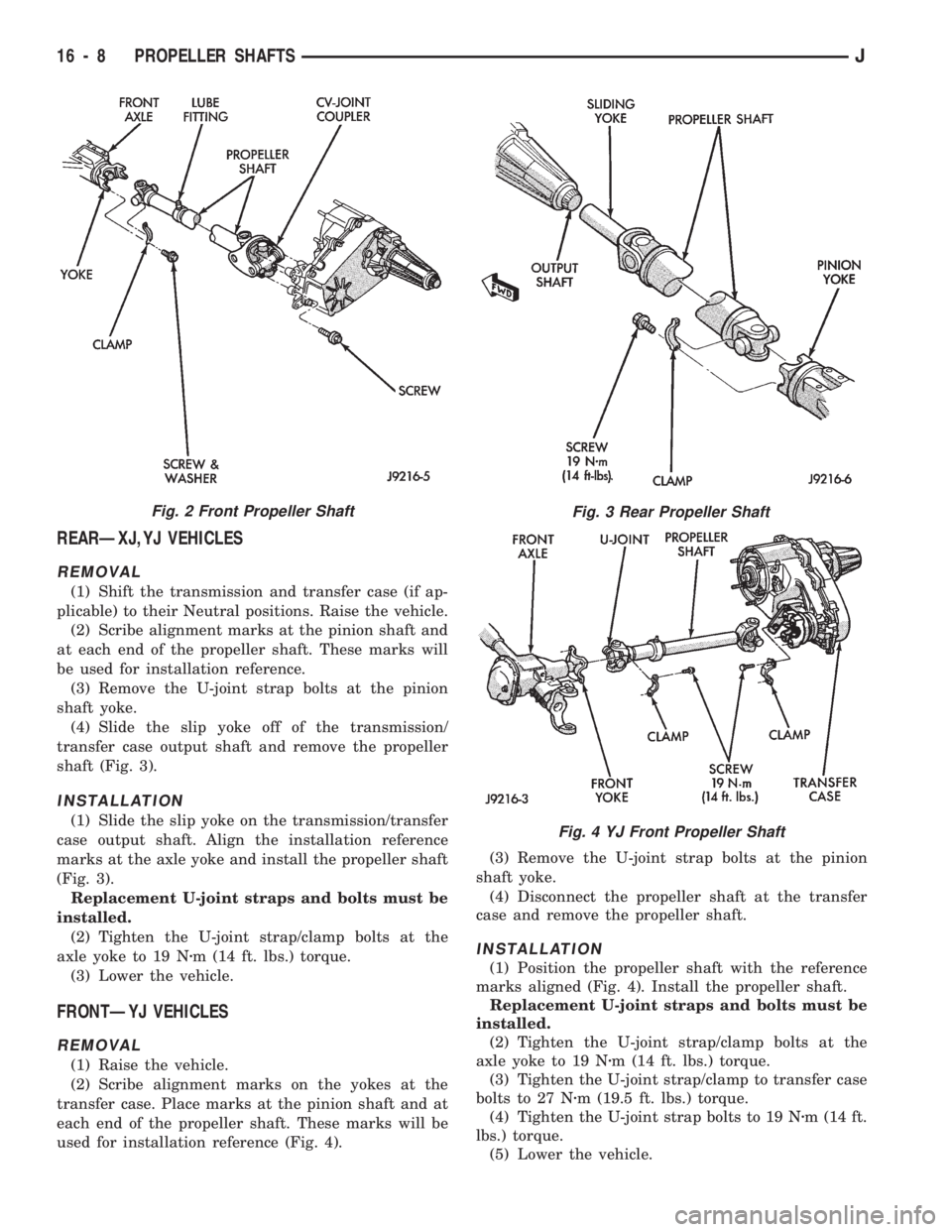
shaft (Fig. 3).
INSTALLATION
(1) Slide the slip yoke on the transmission/transfer
case output shaft. Align the installation reference
marks at the axle yoke and install the propeller shaft
(Fig. 3).
Replacement U-joint straps and bolts must be
installed.
(2) Tighten the U-joint strap/clamp bolts at the
axle yoke to 19 Nzm (14 ft. lbs.) torque.
(3) Lower the vehicle.
FRONTÐYJ VEHICLES
REMOVAL
(1) Raise the vehicle.
(2) Scribe alignment marks on the yokes at the
transfer case. Place marks at the pinion shaft and at
each end of the propeller shaft. These marks will be
used for installation reference (Fig. 4).(3) Remove the U-joint strap bolts at the pinion
shaft yoke.
(4) Disconnect the propeller shaft at the transfer
case and remove the propeller shaft.
INSTALLATION
(1) Position the propeller shaft with the reference
marks aligned (Fig. 4). Install the propeller shaft.
Replacement U-joint straps and bolts must be
installed.
(2) Tighten the U-joint strap/clamp bolts at the
axle yoke to 19 Nzm (14 ft. lbs.) torque.
(3) Tighten the U-joint strap/clamp to transfer case
bolts to 27 Nzm (19.5 ft. lbs.) torque.
(4) Tighten the U-joint strap bolts to 19 Nzm (14 ft.
lbs.) torque.
(5) Lower the vehicle.
Fig. 3 Rear Propeller Shaft
Fig. 4 YJ Front Propeller Shaft
Fig. 2 Front Propeller Shaft
16 - 8 PROPELLER SHAFTSJ
Page 1039 of 1784
pump. The power steering pump is a constant flow
rate and displacement, vane-type pump. The internal
parts in the housing operate submerged in fluid. The
flow control orifice is part of the high pressure line
fitting. The pressure relief valve inside the flow con-
trol valve limits the pump pressure.
Power steering pumps have different pres-
sure rates and are not interchangeable with
other pumps.
The power steering pump is connected to the steer-
ing gear via high pressure and return hose. The
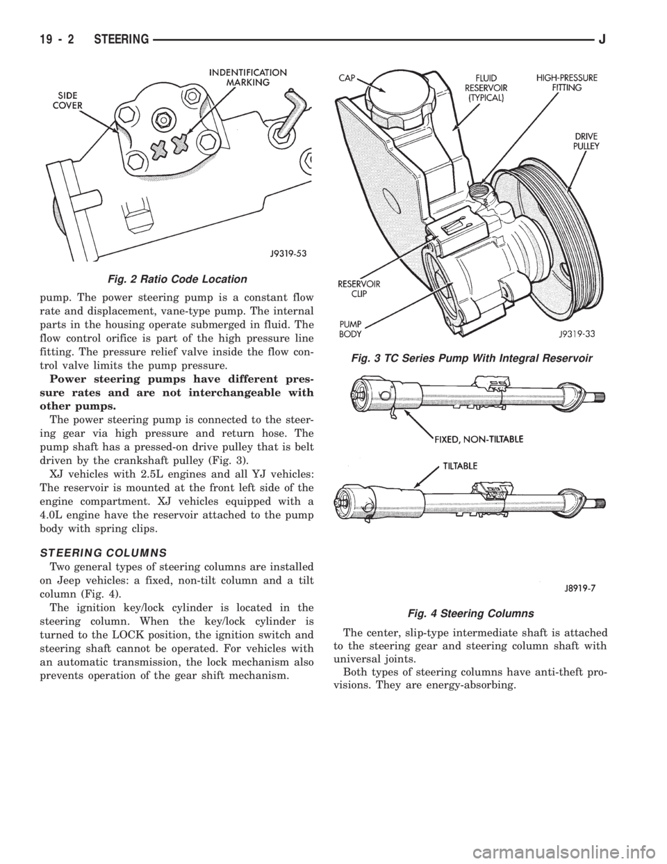
pump shaft has a pressed-on drive pulley that is belt
driven by the crankshaft pulley (Fig. 3).
XJ vehicles with 2.5L engines and all YJ vehicles:
The reservoir is mounted at the front left side of the
engine compartment. XJ vehicles equipped with a
4.0L engine have the reservoir attached to the pump
body with spring clips.
STEERING COLUMNS
Two general types of steering columns are installed
on Jeep vehicles: a fixed, non-tilt column and a tilt
column (Fig. 4).
The ignition key/lock cylinder is located in the
steering column. When the key/lock cylinder is
turned to the LOCK position, the ignition switch and
steering shaft cannot be operated. For vehicles with
an automatic transmission, the lock mechanism also
prevents operation of the gear shift mechanism.The center, slip-type intermediate shaft is attached
to the steering gear and steering column shaft with
universal joints.
Both types of steering columns have anti-theft pro-
visions. They are energy-absorbing.
Fig. 3 TC Series Pump With Integral Reservoir
Fig. 4 Steering Columns
Fig. 2 Ratio Code Location
19 - 2 STEERINGJ
Page 1050 of 1784
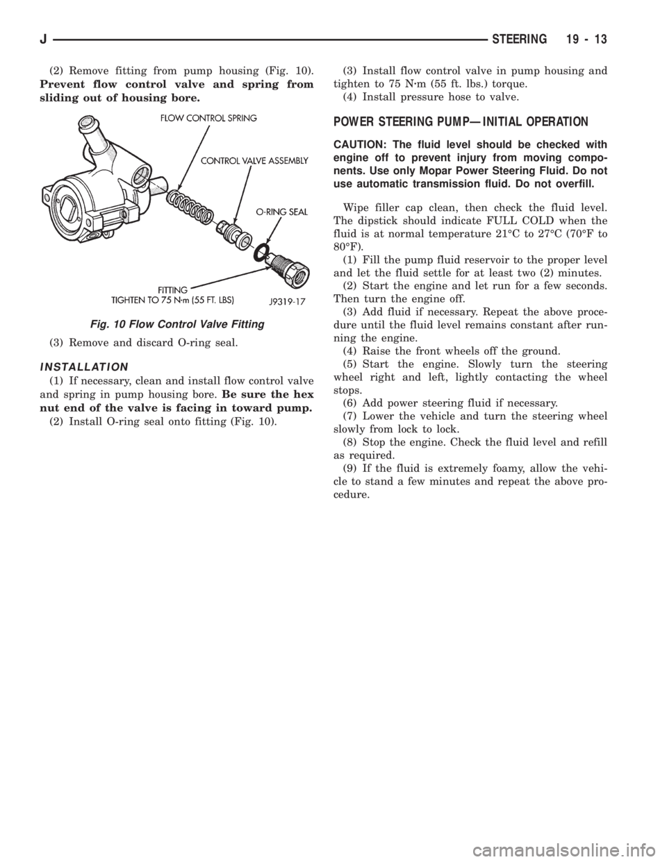
(2) Remove fitting from pump housing (Fig. 10).
Prevent flow control valve and spring from
sliding out of housing bore.
(3) Remove and discard O-ring seal.
INSTALLATION
(1) If necessary, clean and install flow control valve
and spring in pump housing bore.Be sure the hex
nut end of the valve is facing in toward pump.
(2) Install O-ring seal onto fitting (Fig. 10).(3) Install flow control valve in pump housing and
tighten to 75 Nzm (55 ft. lbs.) torque.
(4) Install pressure hose to valve.
POWER STEERING PUMPÐINITIAL OPERATION
CAUTION: The fluid level should be checked with
engine off to prevent injury from moving compo-
nents. Use only Mopar Power Steering Fluid. Do not
use automatic transmission fluid. Do not overfill.
Wipe filler cap clean, then check the fluid level.
The dipstick should indicate FULL COLD when the
fluid is at normal temperature 21ÉC to 27ÉC (70ÉF to
80ÉF).
(1) Fill the pump fluid reservoir to the proper level
and let the fluid settle for at least two (2) minutes.
(2) Start the engine and let run for a few seconds.
Then turn the engine off.
(3) Add fluid if necessary. Repeat the above proce-
dure until the fluid level remains constant after run-
ning the engine.
(4) Raise the front wheels off the ground.
(5) Start the engine. Slowly turn the steering
wheel right and left, lightly contacting the wheel
stops.
(6) Add power steering fluid if necessary.
(7) Lower the vehicle and turn the steering wheel
slowly from lock to lock.
(8) Stop the engine. Check the fluid level and refill
as required.
(9) If the fluid is extremely foamy, allow the vehi-
cle to stand a few minutes and repeat the above pro-
cedure.
Fig. 10 Flow Control Valve Fitting
JSTEERING 19 - 13
Page 1083 of 1784
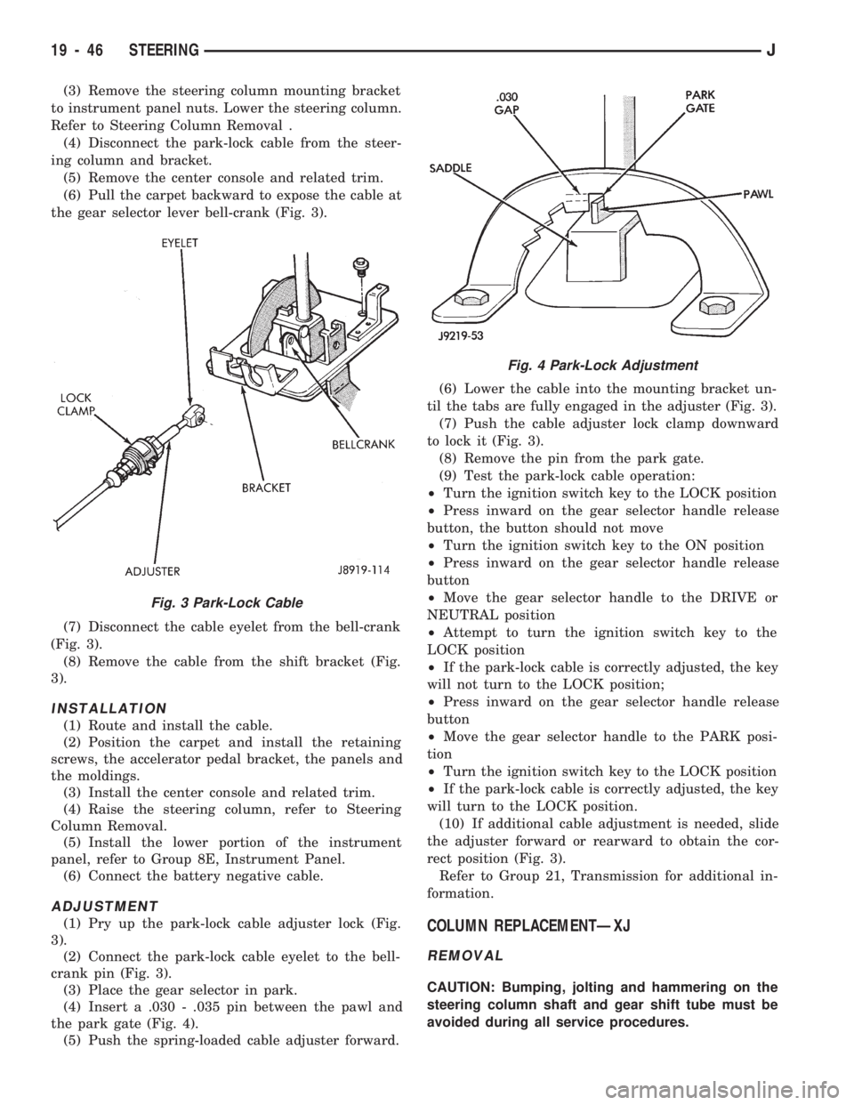
(3) Remove the steering column mounting bracket
to instrument panel nuts. Lower the steering column.
Refer to Steering Column Removal .
(4) Disconnect the park-lock cable from the steer-
ing column and bracket.
(5) Remove the center console and related trim.
(6) Pull the carpet backward to expose the cable at
the gear selector lever bell-crank (Fig. 3).
(7) Disconnect the cable eyelet from the bell-crank
(Fig. 3).
(8) Remove the cable from the shift bracket (Fig.
3).
INSTALLATION
(1) Route and install the cable.
(2) Position the carpet and install the retaining
screws, the accelerator pedal bracket, the panels and
the moldings.
(3) Install the center console and related trim.
(4) Raise the steering column, refer to Steering
Column Removal.
(5) Install the lower portion of the instrument
panel, refer to Group 8E, Instrument Panel.
(6) Connect the battery negative cable.
ADJUSTMENT
(1) Pry up the park-lock cable adjuster lock (Fig.
3).
(2) Connect the park-lock cable eyelet to the bell-
crank pin (Fig. 3).
(3) Place the gear selector in park.
(4) Insert a .030 - .035 pin between the pawl and
the park gate (Fig. 4).
(5) Push the spring-loaded cable adjuster forward.(6) Lower the cable into the mounting bracket un-
til the tabs are fully engaged in the adjuster (Fig. 3).
(7) Push the cable adjuster lock clamp downward
to lock it (Fig. 3).
(8) Remove the pin from the park gate.
(9) Test the park-lock cable operation:
²Turn the ignition switch key to the LOCK position
²Press inward on the gear selector handle release
button, the button should not move
²Turn the ignition switch key to the ON position
²Press inward on the gear selector handle release
button
²Move the gear selector handle to the DRIVE or
NEUTRAL position
²Attempt to turn the ignition switch key to the
LOCK position
²If the park-lock cable is correctly adjusted, the key
will not turn to the LOCK position;
²Press inward on the gear selector handle release
button
²Move the gear selector handle to the PARK posi-
tion
²Turn the ignition switch key to the LOCK position
²If the park-lock cable is correctly adjusted, the key
will turn to the LOCK position.
(10) If additional cable adjustment is needed, slide
the adjuster forward or rearward to obtain the cor-
rect position (Fig. 3).
Refer to Group 21, Transmission for additional in-
formation.COLUMN REPLACEMENTÐXJ
REMOVAL
CAUTION: Bumping, jolting and hammering on the
steering column shaft and gear shift tube must be
avoided during all service procedures.
Fig. 3 Park-Lock Cable
Fig. 4 Park-Lock Adjustment
19 - 46 STEERINGJ
Page 1112 of 1784
TRANSMISSION AND TRANSFER CASE
CONTENTS
page page
30RH/32RH AUTOMATIC TRANSMISSION . . . 66
AW-4 AUTOMATIC TRANSMISSION........ 156AX 15 MANUAL TRANSMISSION.......... 32
AX 4/5 MANUAL TRANSMISSION........... 1
AX 4/5 MANUAL TRANSMISSION
INDEX
page page
Cleaning and Inspection................... 13
Gear Ratios............................. 2
General Information........................ 1
Recommended Lubricant.................... 2
Service Diagnosis......................... 2
Shift Pattern............................. 2Transmission Assembly and Adjustment....... 15
Transmission Disassembly and Overhaul........ 5
Transmission Identification................... 1
Transmission Installation.................... 4
Transmission Removal..................... 3
GENERAL INFORMATION
The AX 4 is a four speed manual transmission. The
AX 5 is a five speed manual transmission. Fifth gear
in the AX 5 is an overdrive range. The shift mecha-
nism in both models is integral and mounted in the
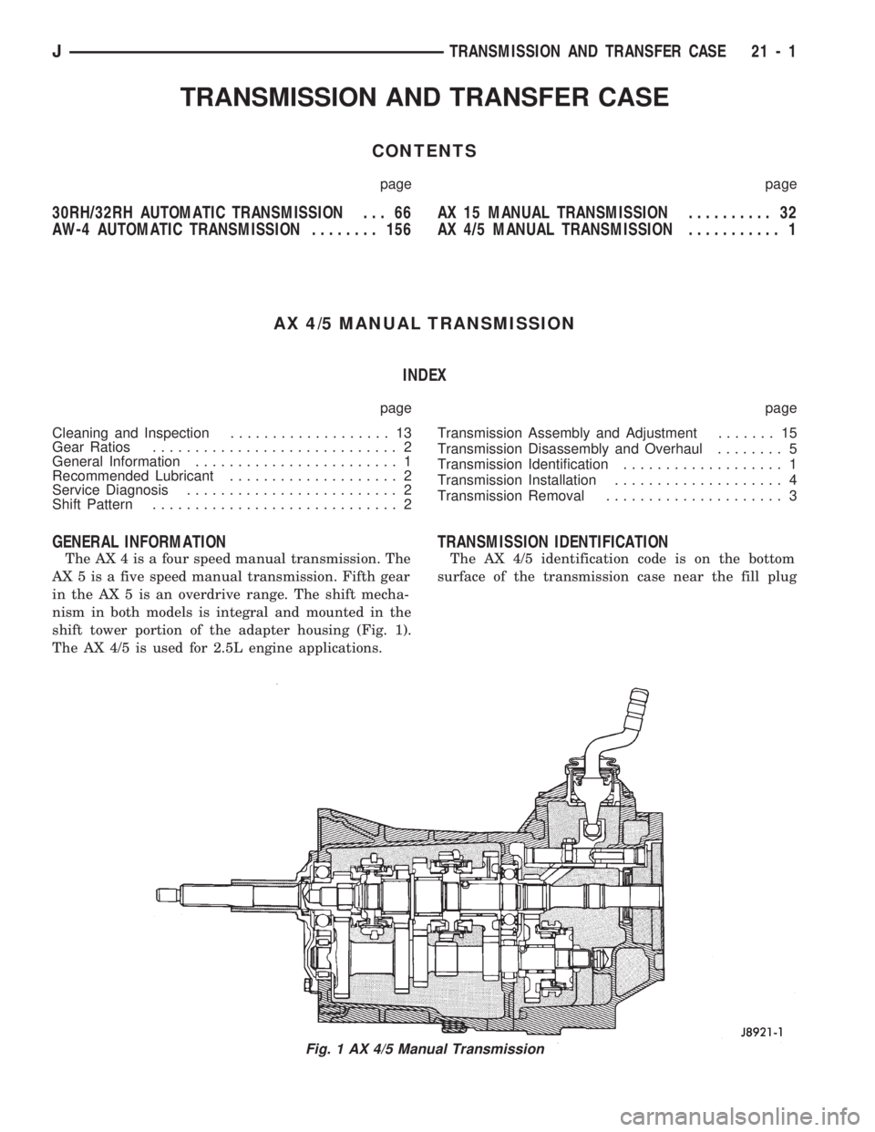
shift tower portion of the adapter housing (Fig. 1).
The AX 4/5 is used for 2.5L engine applications.
TRANSMISSION IDENTIFICATION
The AX 4/5 identification code is on the bottom
surface of the transmission case near the fill plug
Fig. 1 AX 4/5 Manual Transmission
JTRANSMISSION AND TRANSFER CASE 21 - 1
Page 1113 of 1784
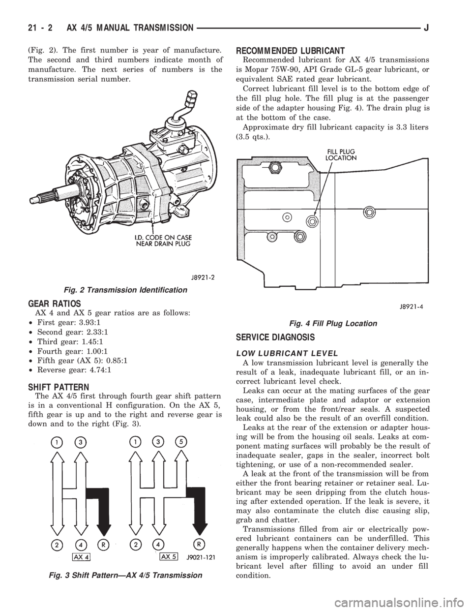
(Fig. 2). The first number is year of manufacture.
The second and third numbers indicate month of
manufacture. The next series of numbers is the
transmission serial number.
GEAR RATIOS
AX 4 and AX 5 gear ratios are as follows:
²First gear: 3.93:1
²Second gear: 2.33:1
²Third gear: 1.45:1
²Fourth gear: 1.00:1
²Fifth gear (AX 5): 0.85:1
²Reverse gear: 4.74:1
SHIFT PATTERN
The AX 4/5 first through fourth gear shift pattern
is in a conventional H configuration. On the AX 5,
fifth gear is up and to the right and reverse gear is
down and to the right (Fig. 3).
RECOMMENDED LUBRICANT
Recommended lubricant for AX 4/5 transmissions
is Mopar 75W-90, API Grade GL-5 gear lubricant, or
equivalent SAE rated gear lubricant.
Correct lubricant fill level is to the bottom edge of
the fill plug hole. The fill plug is at the passenger
side of the adapter housing Fig. 4). The drain plug is
at the bottom of the case.
Approximate dry fill lubricant capacity is 3.3 liters
(3.5 qts.).
SERVICE DIAGNOSIS
LOW LUBRICANT LEVEL
A low transmission lubricant level is generally the
result of a leak, inadequate lubricant fill, or an in-
correct lubricant level check.
Leaks can occur at the mating surfaces of the gear
case, intermediate plate and adaptor or extension
housing, or from the front/rear seals. A suspected
leak could also be the result of an overfill condition.
Leaks at the rear of the extension or adapter hous-
ing will be from the housing oil seals. Leaks at com-
ponent mating surfaces will probably be the result of
inadequate sealer, gaps in the sealer, incorrect bolt
tightening, or use of a non-recommended sealer.
A leak at the front of the transmission will be from
either the front bearing retainer or retainer seal. Lu-
bricant may be seen dripping from the clutch hous-
ing after extended operation. If the leak is severe, it
may also contaminate the clutch disc causing slip,
grab and chatter.
Transmissions filled from air or electrically pow-
ered lubricant containers can be underfilled. This
generally happens when the container delivery mech-
anism is improperly calibrated. Always check the lu-
bricant level after filling to avoid an under fill
condition.
Fig. 2 Transmission Identification
Fig. 3 Shift PatternÐAX 4/5 Transmission
Fig. 4 Fill Plug Location
21 - 2 AX 4/5 MANUAL TRANSMISSIONJ
Page 1114 of 1784
A correct lubricant level check can only be made
when the vehicle is level; use a drive-on hoist to en-
sure this. Also allow the lubricant to settle for a
minute or so before checking. These recommenda-
tions will ensure an accurate check and avoid an un-
der-or-overfill condition.
HARD SHIFTING
Hard shifting is usually caused by a low lubricant
level, improper or contaminated lubricants, compo-
nent damage, incorrect clutch adjustment, or by a
damaged clutch pressure plate or disc.
Substantial lubricant leaks can result in gear, shift
rail, synchro and bearing damage. If a leak goes un-
detected for an extended period, the first indications
of a problem are usually hard shifting and noise.
Incorrect or contaminated lubricants can also con-
tribute to hard shifting. The consequence of using
non-recommended lubricants is noise, excessive wear,
internal bind and hard shifting.
Improper clutch release is a frequent cause of hard
shifting. Incorrect adjustment or a worn, damaged
pressure plate or disc can cause incorrect release. If
the clutch problem is advanced, gear clash during
shifts can result.
Worn or damaged synchro rings can cause gear
clash when shifting into any forward gear. In some
new or rebuilt transmissions, new synchro rings maytend to stick slightly causing hard or noisy shifts. In
most cases, this condition will decline as the rings
wear-in.
TRANSMISSION NOISE
Most manual transmissions make some noise dur-
ing normal operation. Rotating gears can generate a
mild whine that may only be audible at extreme
speeds.
Severe, obviously audible transmission noise is
generally the result of a lubricant problem. Insuffi-
cient, improper, or contaminated lubricant can pro-
mote rapid wear of gears, synchros, shift rails, forks
and bearings. The overheating caused by a lubricant
problem, can also lead to gear breakage.
TRANSMISSION REMOVAL
(1) Shift transmission into first or third gear. Then
raise vehicle on hoist.
(2) Support engine with adjustable jack stand. Be
sure to position wood block between jack and oil pan.
(3) Disconnect necessary exhaust system compo-
nents.
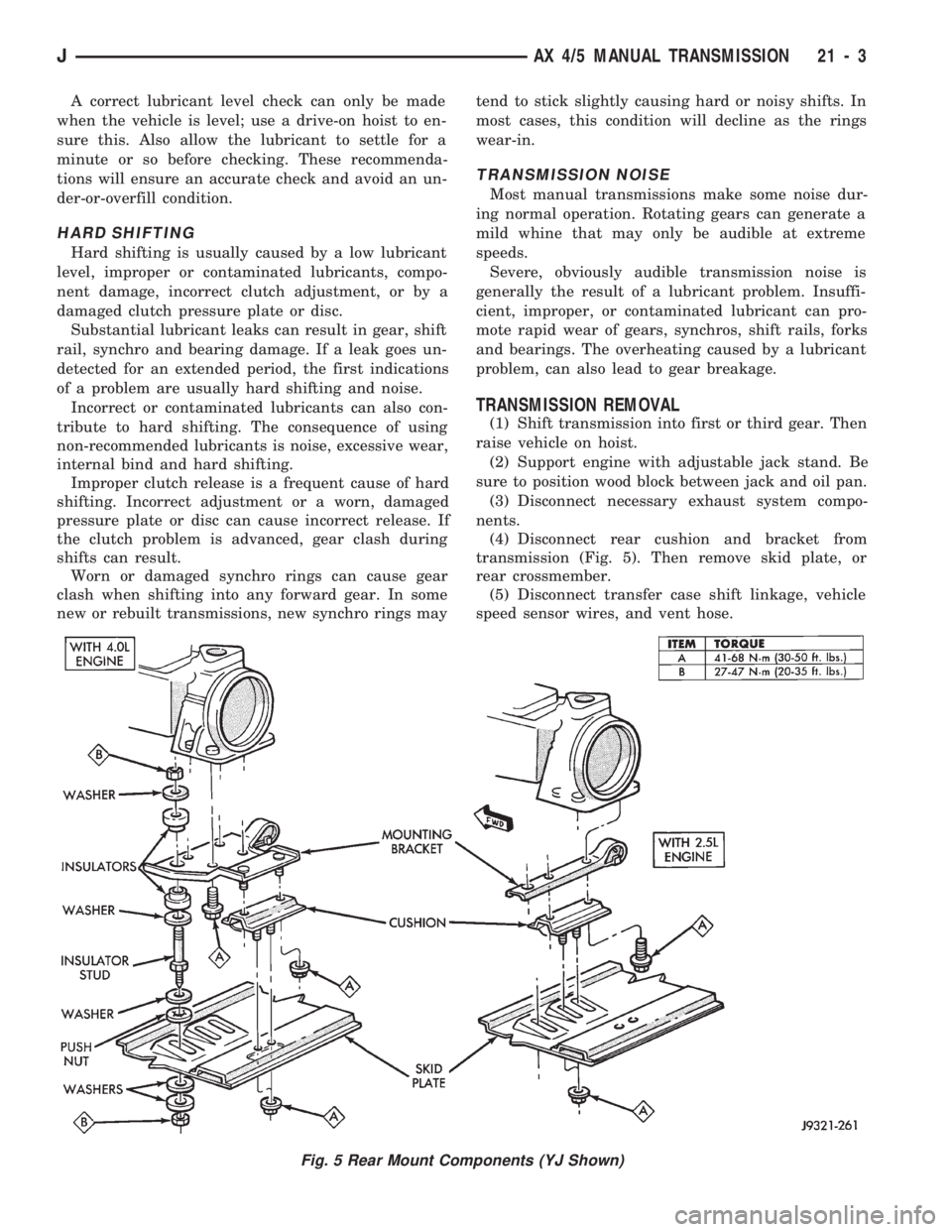
(4) Disconnect rear cushion and bracket from
transmission (Fig. 5). Then remove skid plate, or
rear crossmember.
(5) Disconnect transfer case shift linkage, vehicle
speed sensor wires, and vent hose.
Fig. 5 Rear Mount Components (YJ Shown)
JAX 4/5 MANUAL TRANSMISSION 21 - 3