1994 JEEP CHEROKEE transmission
[x] Cancel search: transmissionPage 903 of 1784
(9) Install the intake and engine exhaust mani-
folds (refer to Group 11, Exhaust System and Intake
Manifold for the proper procedures).
(10) Install the fuel lines and the vacuum advance
hose.
(11) If equipped, attach the power steering pump
and bracket.
(12) Install the push rods, rocker arms, pivots and
bridges in the order they were removed.
(13) Install the engine cylinder head cover.
(14) Attach the air conditioner compressor mount-
ing bracket to the engine cylinder head and block.
Tighten the bolts to 40 Nzm (30 ft. lbs.) torque.
(15) Attach the air conditioning compressor to the
bracket. Tighten the bolts to 27 Nzm (20 ft. lbs.)
torque.
CAUTION: The serpentine drive belt must be routed
correctly. Incorrect routing can cause the water
pump to turn in the opposite direction causing the
engine to overheat.
(16) Install the serpentine drive belt and correctly
tension the belt (refer to Group 7, Cooling System for
the proper procedure).
(17) Install the air cleaner and ducting.
(18) Install the engine cylinder head cover.
(19) Connect the hoses to the engine thermostat
housing and fill the cooling system to the specified
level (refer to Group 7, Cooling Systems for the
proper procedure).
(20) The automatic transmission throttle linkage
and cable must be adjusted after completing the en-
gine cylinder head installation (refer to Group 21,
Transmissions for the proper procedures).
(21) Install the temperature sending unit and con-
nect the wire connector.
(22) Connect the fuel pipe and vacuum advance
hose.
(23) Connect negative cable to battery.
(24) Connect the upper radiator hose and heater
hose at the engine thermostat housing.
(25) Fill the cooling system. Check for leaks.WARNING: USE EXTREME CAUTION WHEN THE
ENGINE IS OPERATING. DO NOT STAND IN DIRECT
LINE WITH THE FAN. DO NOT PUT HANDS NEAR
THE PULLEYS, BELTS OR FAN. DO NOT WEAR
LOOSE CLOTHING.
(26) Operate the engine with the radiator cap off.
Inspect for leaks and continue operating the engine
until the engine thermostat opens. Add coolant, if re-
quired.
VALVE SPRINGS AND OIL SEALS
This procedure can be done with the engine cylin-
der head installed on the block.
REMOVAL
Each valve spring is held in place by a retainer
and a set of conical valve locks. The locks can be re-
moved only by compressing the valve spring.
(1) Remove the engine cylinder head cover.
(2) Remove capscrews, bridge and pivot assemblies
and rocker arms for access to each valve spring to be
removed.
(3) Remove push rods. Retain the push rods,
bridges, pivots and rocker arms in the same order
and position as removed.
(4) Inspect the springs and retainer for cracks and
possible signs of weakening.
(5) Remove the spark plug(s) adjacent to the cylin-
der(s) below the valve springs to be removed.
(6) Install a 14 mm (1/2 inch) (thread size) air hose
adaptor in the spark plug hole. An adaptor can be
constructed by welding an air hose connection to the
body of a spark plug with the porcelain removed.
(7) Connect an air hose to the adapter and apply
air pressure slowly. Maintain at least 621 kPa (90
psi) of air pressure in the cylinder to hold the valves
against their seats. For vehicles equipped with an air
conditioner, use a flexible air adaptor when servicing
the No.1 cylinder.
(8) Tap the retainer or tip with a rawhide hammer
to loosen the lock from the retainer. Use Valve
Spring Compressor Tool MD-998772A to compress
the spring and remove the locks (Fig. 5).
(9) Remove valve spring and retainer (Fig. 5).
(10) Remove valve stem oil seals (Fig. 5). Note the
valve seals are different for intake and exhaust
valves. The top of each seal is marked either INT
(Intake) or EXH (Exhaust). DO NOT mix the seals.
INSPECTION
Inspect the valve stems, especially the grooves. An
Arkansas smooth stone should be used to remove
nicks and high spots.
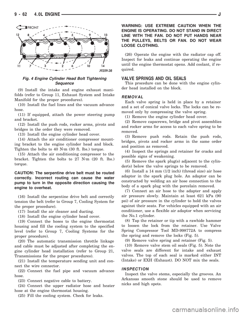
Fig. 4 Engine Cylinder Head Bolt Tightening
Sequence
9 - 62 4.0L ENGINEJ
Page 912 of 1784
(18) Check the ignition timing and adjust as nec-
essary.
(19) Install the grille and bumper, if removed.
(20) Connect negative cable to battery.
CAMSHAFT PIN REPLACEMENT
REMOVAL
WARNING: DO NOT LOOSEN THE RADIATOR
DRAIN COCK WITH THE SYSTEM HOT AND PRES-
SURIZED BECAUSE SERIOUS BURNS FROM COOL-
ANT CAN OCCUR.
(1) Disconnect negative cable from battery.
(2) Drain the radiator. DO NOT waste reusable
coolant. Drain the coolant into a clean container.
(3) Remove the fan and shroud.
(4) Disconnect the radiator overflow tube, radiator
hoses, automatic transmission fluid cooler pipes (if
equipped).
(5) Remove the radiator.
(6) If equipped with air conditioning:
CAUTION: DO NOT loosen or disconnect any air
conditioner system fittings. Move the condenser
and receiver/drier aside as a complete assembly.
(a) Remove the A/C compressor serpentine drive
belt idler pulley.
(b) Disconnect and remove the generator.
(c) Remove the A/C condenser attaching bolts
and move the condenser and receiver/drier assem-
bly up and out of the way.
(7) Remove the serpentine drive belt.
(8) Remove the crankshaft vibration damper.
(9) Remove the timing case cover. Clean the gas-
ket material from the cover.
(10) Remove the thrust pin and tension spring
from the preload bolt head.
(11) Rotate crankshaft until the crankshaft
sprocket timing mark is closest to and on the center
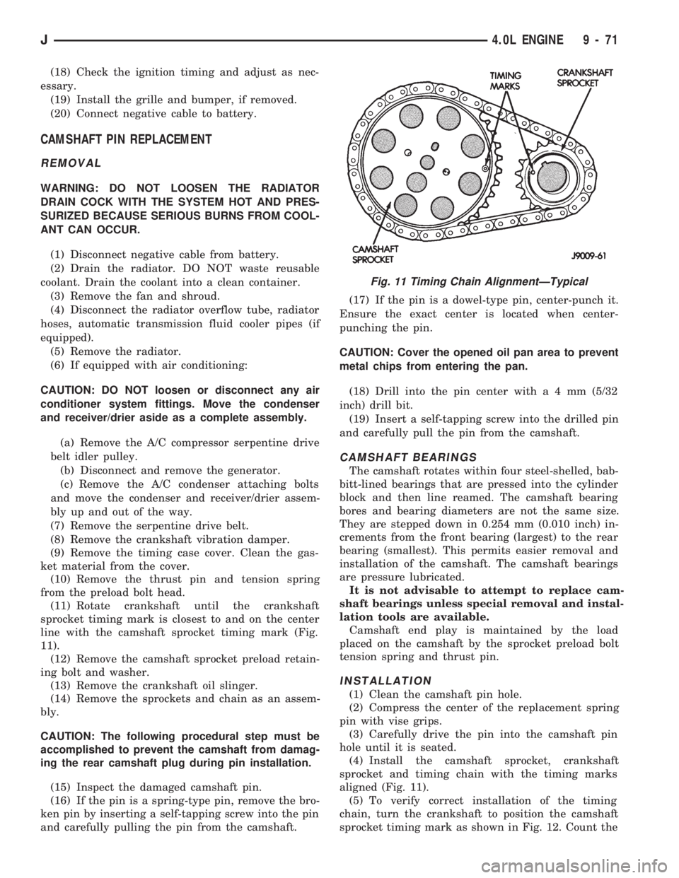
line with the camshaft sprocket timing mark (Fig.
11).
(12) Remove the camshaft sprocket preload retain-
ing bolt and washer.
(13) Remove the crankshaft oil slinger.
(14) Remove the sprockets and chain as an assem-
bly.
CAUTION: The following procedural step must be
accomplished to prevent the camshaft from damag-
ing the rear camshaft plug during pin installation.
(15) Inspect the damaged camshaft pin.
(16) If the pin is a spring-type pin, remove the bro-
ken pin by inserting a self-tapping screw into the pin
and carefully pulling the pin from the camshaft.(17) If the pin is a dowel-type pin, center-punch it.
Ensure the exact center is located when center-
punching the pin.
CAUTION: Cover the opened oil pan area to prevent
metal chips from entering the pan.
(18) Drill into the pin center witha4mm(5/32
inch) drill bit.
(19) Insert a self-tapping screw into the drilled pin
and carefully pull the pin from the camshaft.
CAMSHAFT BEARINGS
The camshaft rotates within four steel-shelled, bab-
bitt-lined bearings that are pressed into the cylinder
block and then line reamed. The camshaft bearing
bores and bearing diameters are not the same size.
They are stepped down in 0.254 mm (0.010 inch) in-
crements from the front bearing (largest) to the rear
bearing (smallest). This permits easier removal and
installation of the camshaft. The camshaft bearings
are pressure lubricated.
It is not advisable to attempt to replace cam-
shaft bearings unless special removal and instal-
lation tools are available.
Camshaft end play is maintained by the load
placed on the camshaft by the sprocket preload bolt
tension spring and thrust pin.
INSTALLATION
(1) Clean the camshaft pin hole.
(2) Compress the center of the replacement spring
pin with vise grips.
(3) Carefully drive the pin into the camshaft pin
hole until it is seated.
(4) Install the camshaft sprocket, crankshaft
sprocket and timing chain with the timing marks
aligned (Fig. 11).
(5) To verify correct installation of the timing
chain, turn the crankshaft to position the camshaft
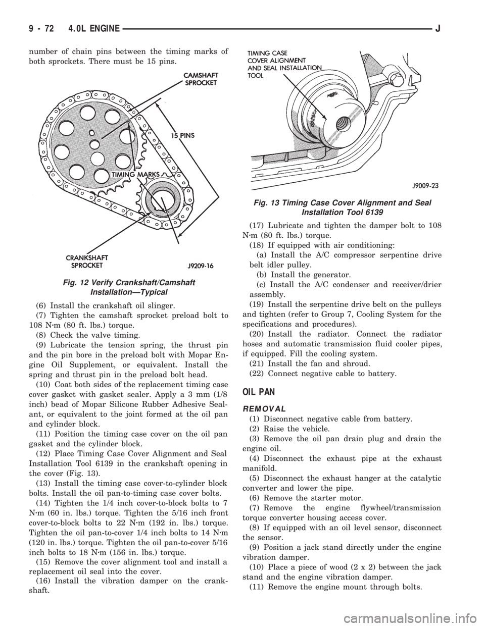
sprocket timing mark as shown in Fig. 12. Count the
Fig. 11 Timing Chain AlignmentÐTypical
J4.0L ENGINE 9 - 71
Page 913 of 1784
number of chain pins between the timing marks of
both sprockets. There must be 15 pins.
(6) Install the crankshaft oil slinger.
(7) Tighten the camshaft sprocket preload bolt to
108 Nzm (80 ft. lbs.) torque.
(8) Check the valve timing.
(9) Lubricate the tension spring, the thrust pin
and the pin bore in the preload bolt with Mopar En-
gine Oil Supplement, or equivalent. Install the
spring and thrust pin in the preload bolt head.
(10) Coat both sides of the replacement timing case
cover gasket with gasket sealer. Applya3mm(1/8
inch) bead of Mopar Silicone Rubber Adhesive Seal-
ant, or equivalent to the joint formed at the oil pan
and cylinder block.
(11) Position the timing case cover on the oil pan
gasket and the cylinder block.
(12) Place Timing Case Cover Alignment and Seal
Installation Tool 6139 in the crankshaft opening in
the cover (Fig. 13).
(13) Install the timing case cover-to-cylinder block
bolts. Install the oil pan-to-timing case cover bolts.
(14) Tighten the 1/4 inch cover-to-block bolts to 7
Nzm (60 in. lbs.) torque. Tighten the 5/16 inch front
cover-to-block bolts to 22 Nzm (192 in. lbs.) torque.
Tighten the oil pan-to-cover 1/4 inch bolts to 14 Nzm
(120 in. lbs.) torque. Tighten the oil pan-to-cover 5/16
inch bolts to 18 Nzm (156 in. lbs.) torque.
(15) Remove the cover alignment tool and install a
replacement oil seal into the cover.
(16) Install the vibration damper on the crank-
shaft.(17) Lubricate and tighten the damper bolt to 108
Nzm (80 ft. lbs.) torque.
(18) If equipped with air conditioning:
(a) Install the A/C compressor serpentine drive
belt idler pulley.
(b) Install the generator.
(c) Install the A/C condenser and receiver/drier
assembly.
(19) Install the serpentine drive belt on the pulleys
and tighten (refer to Group 7, Cooling System for the
specifications and procedures).
(20) Install the radiator. Connect the radiator
hoses and automatic transmission fluid cooler pipes,
if equipped. Fill the cooling system.
(21) Install the fan and shroud.
(22) Connect negative cable to battery.
OIL PAN
REMOVAL
(1) Disconnect negative cable from battery.
(2) Raise the vehicle.
(3) Remove the oil pan drain plug and drain the
engine oil.
(4) Disconnect the exhaust pipe at the exhaust
manifold.
(5) Disconnect the exhaust hanger at the catalytic
converter and lower the pipe.
(6) Remove the starter motor.
(7) Remove the engine flywheel/transmission
torque converter housing access cover.
(8) If equipped with an oil level sensor, disconnect
the sensor.
(9) Position a jack stand directly under the engine
vibration damper.
(10) Place a piece of wood (2 x 2) between the jack
stand and the engine vibration damper.
(11) Remove the engine mount through bolts.
Fig. 12 Verify Crankshaft/Camshaft
InstallationÐTypical
Fig. 13 Timing Case Cover Alignment and Seal
Installation Tool 6139
9 - 72 4.0L ENGINEJ
Page 914 of 1784
(12) Using the jack stand, raise the engine until
adequate clearance is obtained to remove the oil pan.
(13) Remove the oil pan bolts. Carefully slide the
oil pan and gasket to the rear. If equipped with an
oil level sensor, take care not to damage the sensor.
CLEANING
Clean the block and pan gasket surfaces.
INSTALLATION
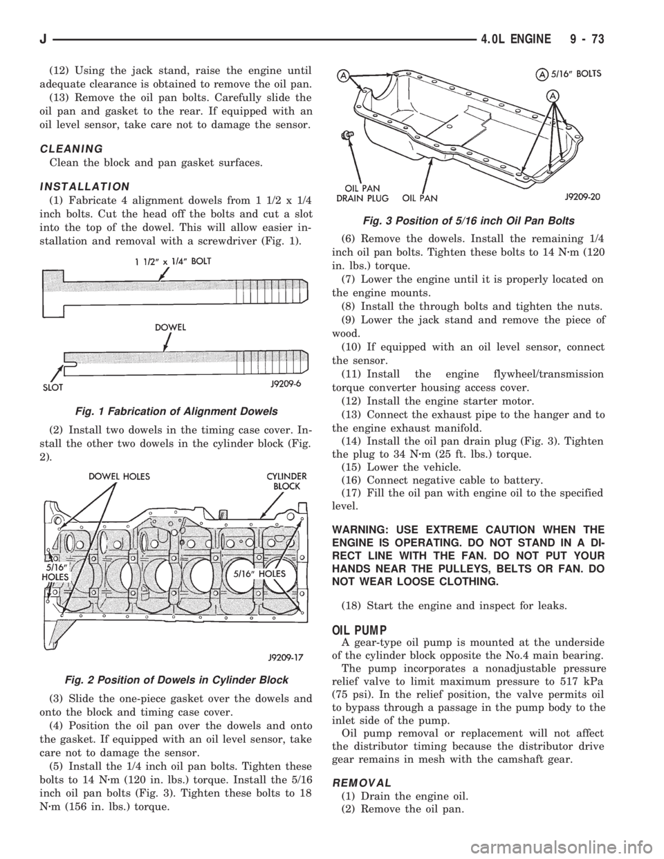
(1) Fabricate 4 alignment dowels from 1 1/2 x 1/4
inch bolts. Cut the head off the bolts and cut a slot
into the top of the dowel. This will allow easier in-
stallation and removal with a screwdriver (Fig. 1).
(2) Install two dowels in the timing case cover. In-
stall the other two dowels in the cylinder block (Fig.
2).
(3) Slide the one-piece gasket over the dowels and
onto the block and timing case cover.
(4) Position the oil pan over the dowels and onto
the gasket. If equipped with an oil level sensor, take
care not to damage the sensor.
(5) Install the 1/4 inch oil pan bolts. Tighten these
bolts to 14 Nzm (120 in. lbs.) torque. Install the 5/16
inch oil pan bolts (Fig. 3). Tighten these bolts to 18
Nzm (156 in. lbs.) torque.(6) Remove the dowels. Install the remaining 1/4
inch oil pan bolts. Tighten these bolts to 14 Nzm (120
in. lbs.) torque.
(7) Lower the engine until it is properly located on
the engine mounts.
(8) Install the through bolts and tighten the nuts.
(9) Lower the jack stand and remove the piece of
wood.
(10) If equipped with an oil level sensor, connect
the sensor.
(11) Install the engine flywheel/transmission
torque converter housing access cover.
(12) Install the engine starter motor.
(13) Connect the exhaust pipe to the hanger and to
the engine exhaust manifold.
(14) Install the oil pan drain plug (Fig. 3). Tighten
the plug to 34 Nzm (25 ft. lbs.) torque.
(15) Lower the vehicle.
(16) Connect negative cable to battery.
(17) Fill the oil pan with engine oil to the specified
level.
WARNING: USE EXTREME CAUTION WHEN THE
ENGINE IS OPERATING. DO NOT STAND IN A DI-
RECT LINE WITH THE FAN. DO NOT PUT YOUR
HANDS NEAR THE PULLEYS, BELTS OR FAN. DO
NOT WEAR LOOSE CLOTHING.
(18) Start the engine and inspect for leaks.
OIL PUMP
A gear-type oil pump is mounted at the underside
of the cylinder block opposite the No.4 main bearing.
The pump incorporates a nonadjustable pressure
relief valve to limit maximum pressure to 517 kPa
(75 psi). In the relief position, the valve permits oil
to bypass through a passage in the pump body to the
inlet side of the pump.
Oil pump removal or replacement will not affect
the distributor timing because the distributor drive
gear remains in mesh with the camshaft gear.
REMOVAL
(1) Drain the engine oil.
(2) Remove the oil pan.
Fig. 1 Fabrication of Alignment Dowels
Fig. 2 Position of Dowels in Cylinder Block
Fig. 3 Position of 5/16 inch Oil Pan Bolts
J4.0L ENGINE 9 - 73
Page 934 of 1784
SERVICE PROCEDURES
INDEX
page page
Catalytic Converter........................ 5
Engine Exhaust ManifoldÐ2.5L Engine......... 7
Engine Exhaust ManifoldÐ4.0L Engine......... 7
Exhaust PipeÐXJ Vehicles.................. 3
Exhaust PipeÐYJ Vehicles.................. 4Intake ManifoldÐ2.5L Engine................ 8
Intake ManifoldÐ4.0L Engine................ 9
Muffler and Exhaust TailpipeÐXJ Vehicles...... 5
Muffler and Exhaust TailpipeÐYJ Vehicles...... 6
EXHAUST PIPEÐXJ VEHICLES
WARNING: IF TORCHES ARE USED WHEN WORK-
ING ON THE EXHAUST SYSTEM, DO NOT ALLOW
THE FLAME NEAR THE FUEL LINES.
REMOVAL
(1) Raise and support the vehicle.
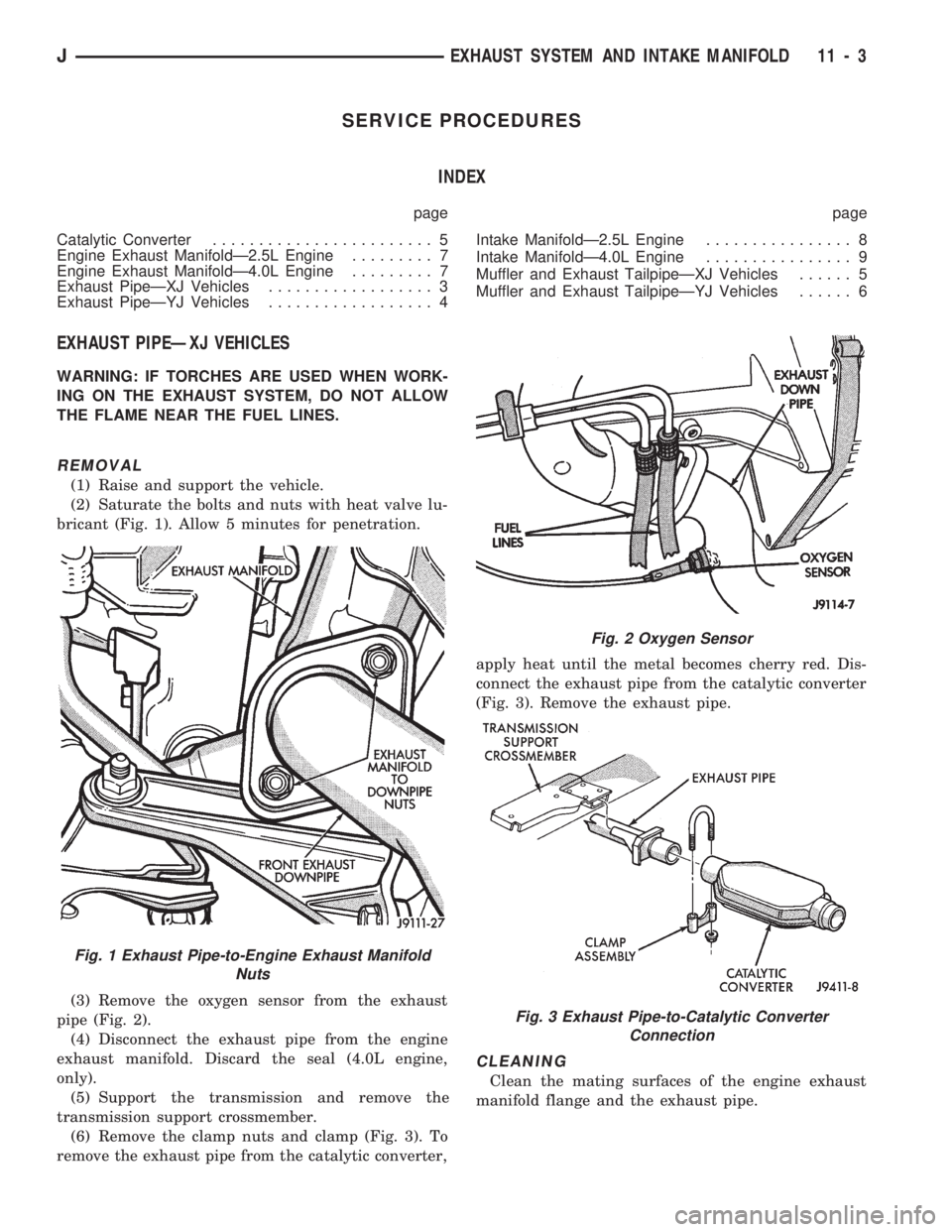
(2) Saturate the bolts and nuts with heat valve lu-
bricant (Fig. 1). Allow 5 minutes for penetration.
(3) Remove the oxygen sensor from the exhaust
pipe (Fig. 2).
(4) Disconnect the exhaust pipe from the engine
exhaust manifold. Discard the seal (4.0L engine,
only).
(5) Support the transmission and remove the
transmission support crossmember.
(6) Remove the clamp nuts and clamp (Fig. 3). To
remove the exhaust pipe from the catalytic converter,apply heat until the metal becomes cherry red. Dis-
connect the exhaust pipe from the catalytic converter
(Fig. 3). Remove the exhaust pipe.
CLEANING
Clean the mating surfaces of the engine exhaust
manifold flange and the exhaust pipe.
Fig. 1 Exhaust Pipe-to-Engine Exhaust Manifold
Nuts
Fig. 2 Oxygen Sensor
Fig. 3 Exhaust Pipe-to-Catalytic Converter
Connection
JEXHAUST SYSTEM AND INTAKE MANIFOLD 11 - 3
Page 935 of 1784
INSTALLATION
(1) Assemble exhaust pipe to manifold and cata-
lytic converter loosely to permit proper alignment of
all parts.
(2) Use a new clamp at the exhaust pipe to cata-
lytic converter connection and tighten the nuts to 61
NzIm (45 ft. lbs.) torque.
(3) Connect the exhaust pipe to the engine exhaust
manifold using new nuts. Install a new seal between
the exhaust manifold and the exhaust pipe (4.0L en-
gine, only). Tighten the nuts to 31 Nzm (23 ft. lbs.)
torque (Fig. 1).
(4) Align the transmission support crossmember to
the exhaust pipe (Fig. 3) and position on the sill.
Tighten the crossmember-to-sill bolts to 41 Nzm (30
ft. lbs.) torque. Remove the support from the trans-
mission.
(5) Coat the oxygen sensor with anti-seize com-
pound. Install the sensor and tighten the nut to 48
Nzm (35 ft. lbs.) torque.
(6) Lower the vehicle.
(7) Start the engine and inspect for exhaust leaks
and exhaust system contact with the body panels.
Adjust the alignment, if needed.
EXHAUST PIPEÐYJ VEHICLES
WARNING: IF TORCHES ARE USED WHEN WORK-
ING ON THE EXHAUST SYSTEM, DO NOT ALLOW
THE FLAME NEAR THE FUEL LINES.
REMOVAL
(1) Raise and support the vehicle.
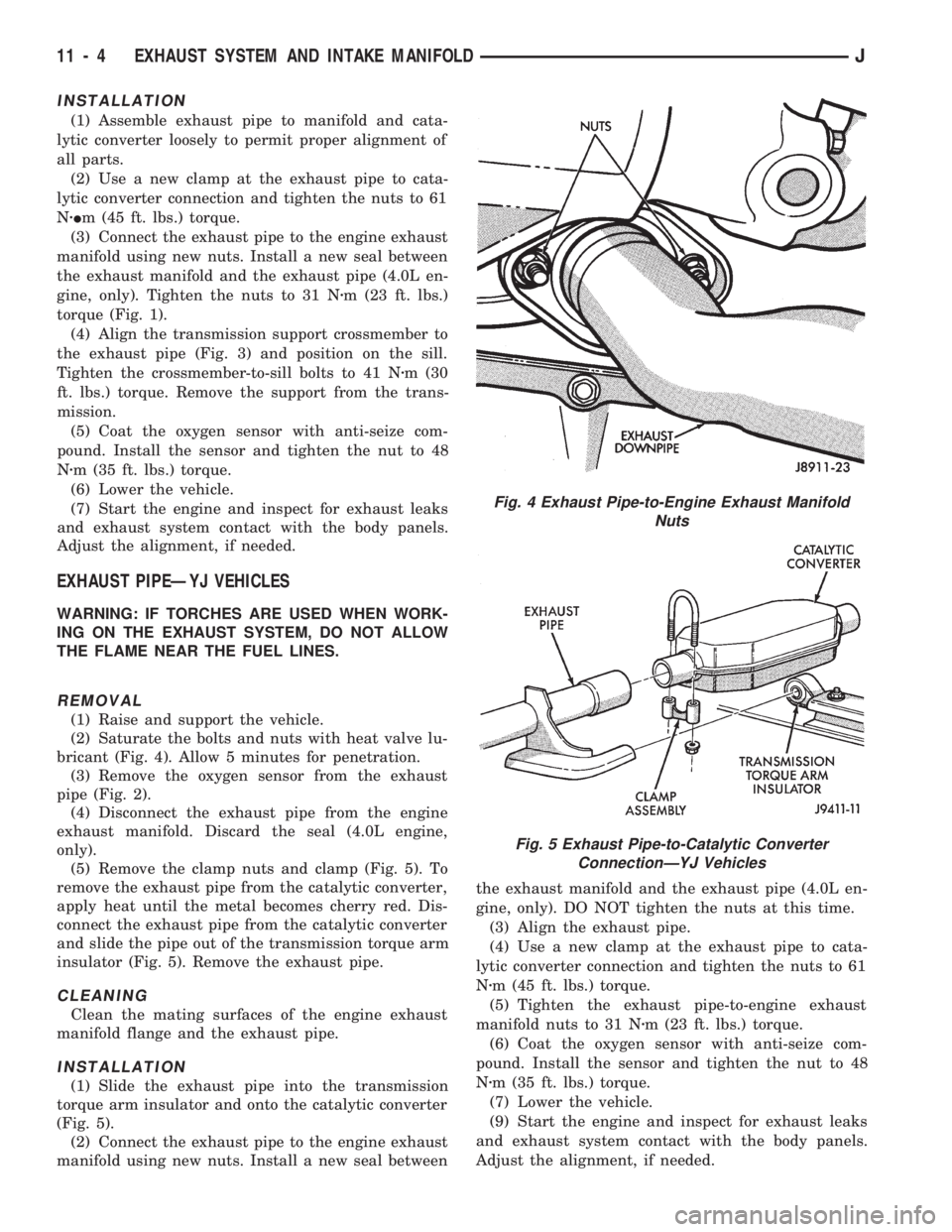
(2) Saturate the bolts and nuts with heat valve lu-
bricant (Fig. 4). Allow 5 minutes for penetration.
(3) Remove the oxygen sensor from the exhaust
pipe (Fig. 2).
(4) Disconnect the exhaust pipe from the engine
exhaust manifold. Discard the seal (4.0L engine,
only).
(5) Remove the clamp nuts and clamp (Fig. 5). To
remove the exhaust pipe from the catalytic converter,
apply heat until the metal becomes cherry red. Dis-
connect the exhaust pipe from the catalytic converter
and slide the pipe out of the transmission torque arm
insulator (Fig. 5). Remove the exhaust pipe.
CLEANING
Clean the mating surfaces of the engine exhaust
manifold flange and the exhaust pipe.
INSTALLATION
(1) Slide the exhaust pipe into the transmission
torque arm insulator and onto the catalytic converter
(Fig. 5).
(2) Connect the exhaust pipe to the engine exhaust
manifold using new nuts. Install a new seal betweenthe exhaust manifold and the exhaust pipe (4.0L en-
gine, only). DO NOT tighten the nuts at this time.
(3) Align the exhaust pipe.
(4) Use a new clamp at the exhaust pipe to cata-
lytic converter connection and tighten the nuts to 61
Nzm (45 ft. lbs.) torque.
(5) Tighten the exhaust pipe-to-engine exhaust
manifold nuts to 31 Nzm (23 ft. lbs.) torque.
(6) Coat the oxygen sensor with anti-seize com-
pound. Install the sensor and tighten the nut to 48
Nzm (35 ft. lbs.) torque.
(7) Lower the vehicle.
(9) Start the engine and inspect for exhaust leaks
and exhaust system contact with the body panels.
Adjust the alignment, if needed.
Fig. 4 Exhaust Pipe-to-Engine Exhaust Manifold
Nuts
Fig. 5 Exhaust Pipe-to-Catalytic Converter
ConnectionÐYJ Vehicles
11 - 4 EXHAUST SYSTEM AND INTAKE MANIFOLDJ
Page 940 of 1784
CAUTION: Ensure that the accessory drive belt is
routed correctly. Failure to do so can cause the wa-
ter pump to turn in the opposite direction resulting
in engine overheating. Refer to Group 7, Cooling
System for the proper procedure.
(10) Tension the accessory drive belt. Refer to
Group 7, Cooling System for the proper procedure.
(11) Connect the air inlet hose to the throttle body
and the air cleaner.
(12) Connect the battery negative cable.
(13) Start the engine and check for leaks.
INTAKE MANIFOLDÐ4.0L ENGINE
The intake and engine exhaust manifolds on the
4.0L engine must be removed and installed together.
The two manifolds use a common gasket at the cyl-
inder head.
REMOVAL
(1) Disconnect the battery negative cable.
(2) Remove air cleaner inlet hose from throttle
plate assembly.
(3) Remove the air cleaner assembly.
(4) Remove the throttle cable, cruise control cable (if
equipped) and the transmission line pressure cable.
(5) Disconnect all electrical connectors on the in-
take manifold.
(6) Disconnect and remove the fuel supply and re-
turn lines from the fuel rail assembly (refer to Group
14, Fuel System).
(7) Loosen the accessory drive belt (refer to Group
7, Cooling System). Loosen the tensioner.
(8) Remove the power steering pump and bracket
from the intake manifold and set aside.
(9) Remove the fuel rail and injectors (refer to
Group 14, Fuel System).
(10) Raise the vehicle.
(11) Disconnect the exhaust pipe from the engine
exhaust manifold. Discard the seal.
(12) Lower the vehicle.
(13) Remove the intake manifold and engine ex-
haust manifold.
CLEANING
Clean the mating surfaces of the cylinder head and
the manifold if the original manifold is to be installed.
If the manifold is being replaced, ensure all the fit-
ting, etc. are transferred to the replacement manifold.
INSTALLATION
(1) Install a new exhaust/intake manifold gasket
over the alignment dowels on the cylinder head.
(2) Position the engine exhaust manifold to the
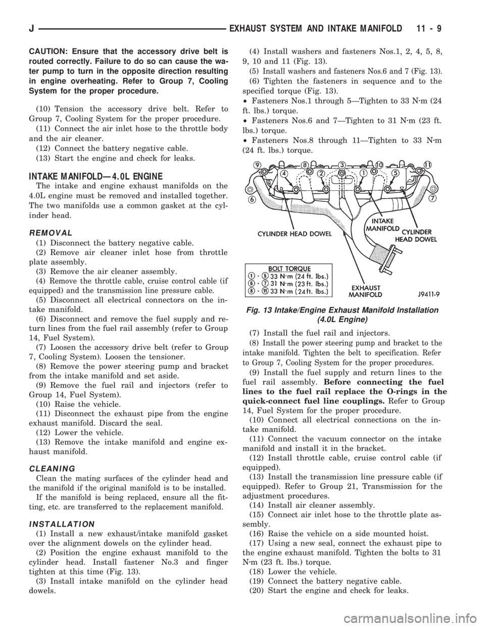
cylinder head. Install fastener No.3 and finger
tighten at this time (Fig. 13).
(3) Install intake manifold on the cylinder head
dowels.(4) Install washers and fasteners Nos.1, 2, 4, 5, 8,
9, 10 and 11 (Fig. 13).
(5) Install washers and fasteners Nos.6 and 7 (Fig. 13).
(6) Tighten the fasteners in sequence and to the
specified torque (Fig. 13).
²Fasteners Nos.1 through 5ÐTighten to 33 Nzm (24
ft. lbs.) torque.
²Fasteners Nos.6 and 7ÐTighten to 31 Nzm (23 ft.
lbs.) torque.
²Fasteners Nos.8 through 11ÐTighten to 33 Nzm
(24 ft. lbs.) torque.
(7) Install the fuel rail and injectors.
(8) Install the power steering pump and bracket to the
intake manifold. Tighten the belt to specification. Refer
to Group 7, Cooling System for the proper procedures.
(9) Install the fuel supply and return lines to the
fuel rail assembly.Before connecting the fuel
lines to the fuel rail replace the O-rings in the
quick-connect fuel line couplings.Refer to Group
14, Fuel System for the proper procedure.
(10) Connect all electrical connections on the in-
take manifold.
(11) Connect the vacuum connector on the intake
manifold and install it in the bracket.
(12) Install throttle cable, cruise control cable (if
equipped).
(13) Install the transmission line pressure cable (if
equipped). Refer to Group 21, Transmission for the
adjustment procedures.
(14) Install air cleaner assembly.
(15) Connect air inlet hose to the throttle plate as-
sembly.
(16) Raise the vehicle on a side mounted hoist.
(17) Using a new seal, connect the exhaust pipe to
the engine exhaust manifold. Tighten the bolts to 31
Nzm (23 ft. lbs.) torque.
(18) Lower the vehicle.
(19) Connect the battery negative cable.
(20) Start the engine and check for leaks.
Fig. 13 Intake/Engine Exhaust Manifold Installation
(4.0L Engine)
JEXHAUST SYSTEM AND INTAKE MANIFOLD 11 - 9
Page 956 of 1784
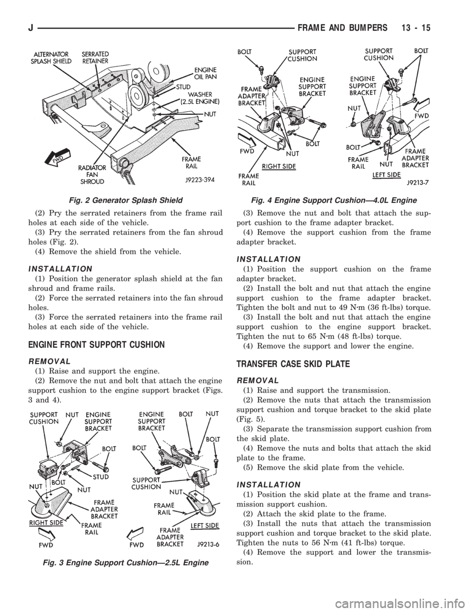
(2) Pry the serrated retainers from the frame rail
holes at each side of the vehicle.
(3) Pry the serrated retainers from the fan shroud
holes (Fig. 2).
(4) Remove the shield from the vehicle.
INSTALLATION
(1) Position the generator splash shield at the fan
shroud and frame rails.
(2) Force the serrated retainers into the fan shroud
holes.
(3) Force the serrated retainers into the frame rail
holes at each side of the vehicle.
ENGINE FRONT SUPPORT CUSHION
REMOVAL
(1) Raise and support the engine.
(2) Remove the nut and bolt that attach the engine
support cushion to the engine support bracket (Figs.
3 and 4).(3) Remove the nut and bolt that attach the sup-
port cushion to the frame adapter bracket.
(4) Remove the support cushion from the frame
adapter bracket.
INSTALLATION
(1) Position the support cushion on the frame
adapter bracket.
(2) Install the bolt and nut that attach the engine
support cushion to the frame adapter bracket.
Tighten the bolt and nut to 49 Nzm (36 ft-lbs) torque.
(3) Install the bolt and nut that attach the engine
support cushion to the engine support bracket.
Tighten the nut to 65 Nzm (48 ft-lbs) torque.
(4) Remove the support and lower the engine.
TRANSFER CASE SKID PLATE
REMOVAL
(1) Raise and support the transmission.
(2) Remove the nuts that attach the transmission
support cushion and torque bracket to the skid plate
(Fig. 5).
(3) Separate the transmission support cushion from
the skid plate.
(4) Remove the nuts and bolts that attach the skid
plate to the frame.
(5) Remove the skid plate from the vehicle.
INSTALLATION
(1) Position the skid plate at the frame and trans-
mission support cushion.
(2) Attach the skid plate to the frame.
(3) Install the nuts that attach the transmission
support cushion and torque bracket to the skid plate.
Tighten the nuts to 56 Nzm (41 ft-lbs) torque.
(4) Remove the support and lower the transmis-
sion.
Fig. 2 Generator Splash Shield
Fig. 3 Engine Support CushionÐ2.5L Engine
Fig. 4 Engine Support CushionÐ4.0L Engine
JFRAME AND BUMPERS 13 - 15