1994 JEEP CHEROKEE tailgate
[x] Cancel search: tailgatePage 1615 of 1784
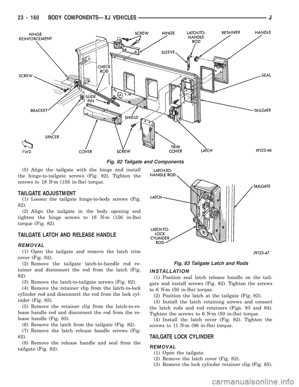
(5) Align the tailgate with the hinge and install
the hinge-to-tailgate screws (Fig. 82). Tighten the
screws to 18 Nzm (156 in-lbs) torque.
TAILGATE ADJUSTMENT
(1) Loosen the tailgate hinge-to-body screws (Fig.
82).
(2) Align the tailgate in the body opening and
tighten the hinge screws to 18 Nzm (156 in-lbs)
torque (Fig. 82).
TAILGATE LATCH AND RELEASE HANDLE
REMOVAL
(1) Open the tailgate and remove the latch trim
cover (Fig. 82).
(2) Remove the tailgate latch-to-handle rod re-
tainer and disconnect the rod from the latch (Fig.
82).
(3) Remove the latch-to-tailgate screws (Fig. 82).
(4) Remove the retainer clip from the latch-to-lock
cylinder rod and disconnect the rod from the lock cyl-
inder (Fig. 83).
(5) Remove the retainer clip from the latch-to-re-
lease handle rod and disconnect the rod from the re-
lease handle (Fig. 83).
(6) Remove the latch from the tailgate (Fig. 82).
(7) Remove the latch release handle screws (Fig.
82).
(8) Remove the release handle and seal from the
tailgate (Fig. 82).
INSTALLATION
(1) Position seal latch release handle on the tail-
gate and install screws (Fig. 82). Tighten the screws
to6Nzm (50 in-lbs) torque.
(2) Position the latch at the tailgate (Fig. 82).
(3) Install the latch retaining screws and connect
the latch rods and rod retainers (Figs. 83 and 84).
Tighten the screws to 6 Nzm (50 in-lbs) torque.
(4) Install the latch cover (Fig. 82). Tighten the
screws to 11 Nzm (96 in-lbs) torque.
TAILGATE LOCK CYLINDER
REMOVAL
(1) Open the tailgate.
(2) Remove the latch cover (Fig. 82).
(3) Remove the lock cylinder retainer clip (Fig. 85).
Fig. 82 Tailgate and Components
Fig. 83 Tailgate Latch and Rods
23 - 160 BODY COMPONENTSÐXJ VEHICLESJ
Page 1616 of 1784
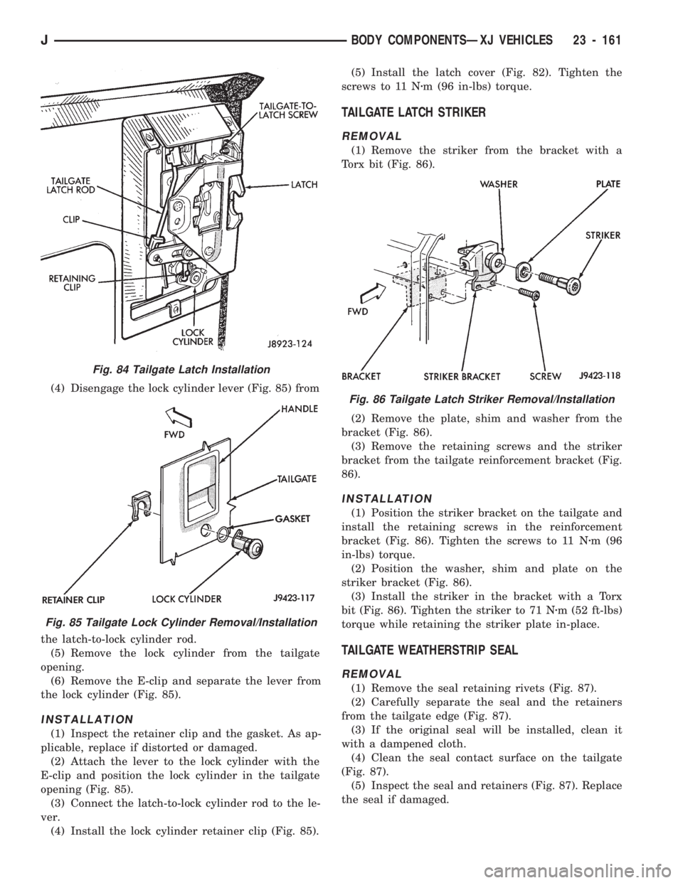
(4) Disengage the lock cylinder lever (Fig. 85) from
the latch-to-lock cylinder rod.
(5) Remove the lock cylinder from the tailgate
opening.
(6) Remove the E-clip and separate the lever from
the lock cylinder (Fig. 85).
INSTALLATION
(1) Inspect the retainer clip and the gasket. As ap-
plicable, replace if distorted or damaged.
(2) Attach the lever to the lock cylinder with the
E-clip and position the lock cylinder in the tailgate
opening (Fig. 85).
(3) Connect the latch-to-lock cylinder rod to the le-
ver.
(4) Install the lock cylinder retainer clip (Fig. 85).(5) Install the latch cover (Fig. 82). Tighten the
screws to 11 Nzm (96 in-lbs) torque.
TAILGATE LATCH STRIKER
REMOVAL
(1) Remove the striker from the bracket with a
Torx bit (Fig. 86).
(2) Remove the plate, shim and washer from the
bracket (Fig. 86).
(3) Remove the retaining screws and the striker
bracket from the tailgate reinforcement bracket (Fig.
86).
INSTALLATION
(1) Position the striker bracket on the tailgate and
install the retaining screws in the reinforcement
bracket (Fig. 86). Tighten the screws to 11 Nzm (96
in-lbs) torque.
(2) Position the washer, shim and plate on the
striker bracket (Fig. 86).
(3) Install the striker in the bracket with a Torx
bit (Fig. 86). Tighten the striker to 71 Nzm (52 ft-lbs)
torque while retaining the striker plate in-place.
TAILGATE WEATHERSTRIP SEAL
REMOVAL
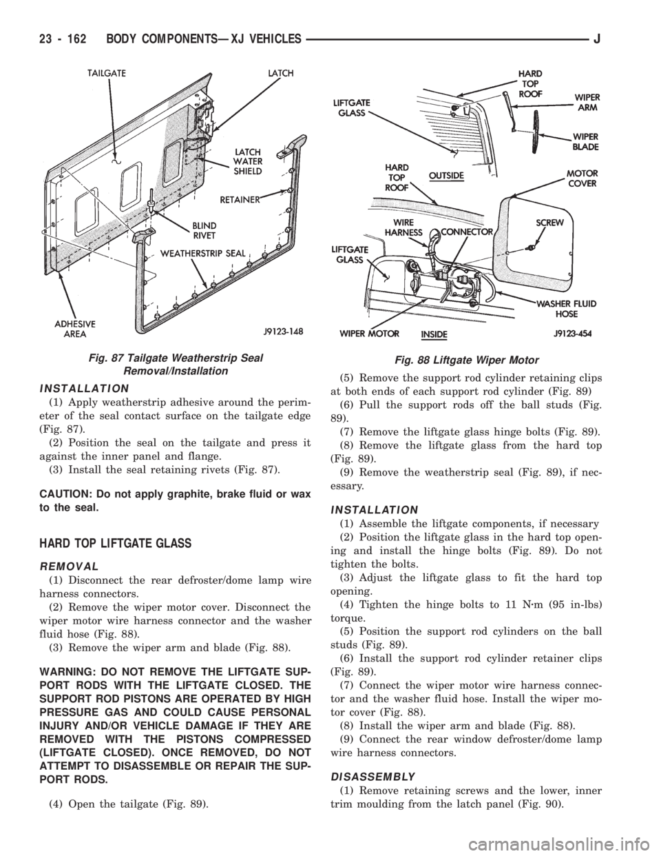
(1) Remove the seal retaining rivets (Fig. 87).
(2) Carefully separate the seal and the retainers
from the tailgate edge (Fig. 87).
(3) If the original seal will be installed, clean it
with a dampened cloth.
(4) Clean the seal contact surface on the tailgate
(Fig. 87).
(5) Inspect the seal and retainers (Fig. 87). Replace
the seal if damaged.
Fig. 84 Tailgate Latch Installation
Fig. 85 Tailgate Lock Cylinder Removal/Installation
Fig. 86 Tailgate Latch Striker Removal/Installation
JBODY COMPONENTSÐXJ VEHICLES 23 - 161
Page 1617 of 1784
INSTALLATION
(1) Apply weatherstrip adhesive around the perim-
eter of the seal contact surface on the tailgate edge
(Fig. 87).
(2) Position the seal on the tailgate and press it
against the inner panel and flange.
(3) Install the seal retaining rivets (Fig. 87).
CAUTION: Do not apply graphite, brake fluid or wax
to the seal.
HARD TOP LIFTGATE GLASS
REMOVAL
(1) Disconnect the rear defroster/dome lamp wire
harness connectors.
(2) Remove the wiper motor cover. Disconnect the
wiper motor wire harness connector and the washer
fluid hose (Fig. 88).
(3) Remove the wiper arm and blade (Fig. 88).
WARNING: DO NOT REMOVE THE LIFTGATE SUP-
PORT RODS WITH THE LIFTGATE CLOSED. THE
SUPPORT ROD PISTONS ARE OPERATED BY HIGH
PRESSURE GAS AND COULD CAUSE PERSONAL
INJURY AND/OR VEHICLE DAMAGE IF THEY ARE
REMOVED WITH THE PISTONS COMPRESSED
(LIFTGATE CLOSED). ONCE REMOVED, DO NOT
ATTEMPT TO DISASSEMBLE OR REPAIR THE SUP-
PORT RODS.
(4) Open the tailgate (Fig. 89).(5) Remove the support rod cylinder retaining clips
at both ends of each support rod cylinder (Fig. 89)
(6) Pull the support rods off the ball studs (Fig.
89).
(7) Remove the liftgate glass hinge bolts (Fig. 89).
(8) Remove the liftgate glass from the hard top
(Fig. 89).
(9) Remove the weatherstrip seal (Fig. 89), if nec-
essary.
INSTALLATION
(1) Assemble the liftgate components, if necessary
(2) Position the liftgate glass in the hard top open-
ing and install the hinge bolts (Fig. 89). Do not
tighten the bolts.
(3) Adjust the liftgate glass to fit the hard top
opening.
(4) Tighten the hinge bolts to 11 Nzm (95 in-lbs)
torque.
(5) Position the support rod cylinders on the ball
studs (Fig. 89).
(6) Install the support rod cylinder retainer clips
(Fig. 89).
(7) Connect the wiper motor wire harness connec-
tor and the washer fluid hose. Install the wiper mo-
tor cover (Fig. 88).
(8) Install the wiper arm and blade (Fig. 88).
(9) Connect the rear window defroster/dome lamp
wire harness connectors.
DISASSEMBLY
(1) Remove retaining screws and the lower, inner
trim moulding from the latch panel (Fig. 90).
Fig. 87 Tailgate Weatherstrip Seal
Removal/InstallationFig. 88 Liftgate Wiper Motor
23 - 162 BODY COMPONENTSÐXJ VEHICLESJ
Page 1618 of 1784
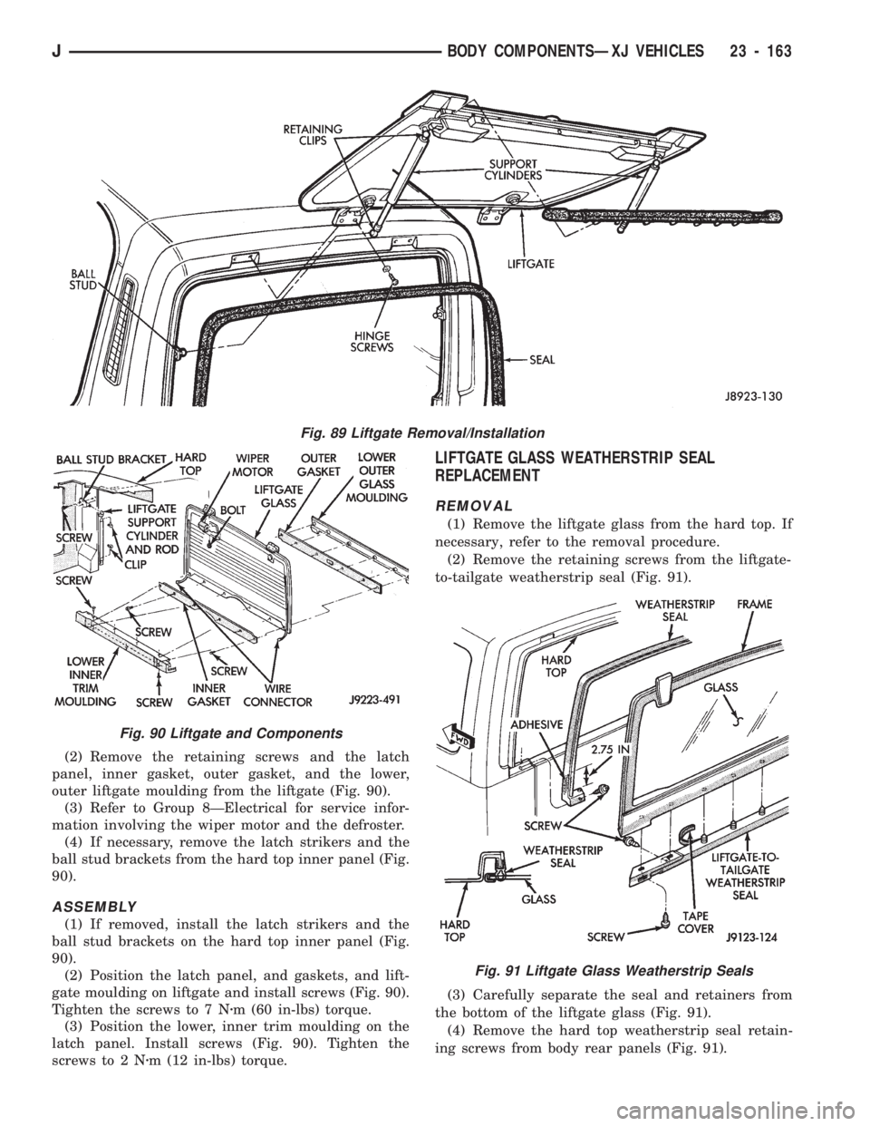
(2) Remove the retaining screws and the latch
panel, inner gasket, outer gasket, and the lower,
outer liftgate moulding from the liftgate (Fig. 90).
(3) Refer to Group 8ÐElectrical for service infor-
mation involving the wiper motor and the defroster.
(4) If necessary, remove the latch strikers and the
ball stud brackets from the hard top inner panel (Fig.
90).
ASSEMBLY
(1) If removed, install the latch strikers and the
ball stud brackets on the hard top inner panel (Fig.
90).
(2) Position the latch panel, and gaskets, and lift-
gate moulding on liftgate and install screws (Fig. 90).
Tighten the screws to 7 Nzm (60 in-lbs) torque.
(3) Position the lower, inner trim moulding on the
latch panel. Install screws (Fig. 90). Tighten the
screws to 2 Nzm (12 in-lbs) torque.
LIFTGATE GLASS WEATHERSTRIP SEAL
REPLACEMENT
REMOVAL
(1) Remove the liftgate glass from the hard top. If
necessary, refer to the removal procedure.
(2) Remove the retaining screws from the liftgate-
to-tailgate weatherstrip seal (Fig. 91).
(3) Carefully separate the seal and retainers from
the bottom of the liftgate glass (Fig. 91).
(4) Remove the hard top weatherstrip seal retain-
ing screws from body rear panels (Fig. 91).
Fig. 91 Liftgate Glass Weatherstrip Seals
Fig. 89 Liftgate Removal/Installation
Fig. 90 Liftgate and Components
JBODY COMPONENTSÐXJ VEHICLES 23 - 163
Page 1619 of 1784
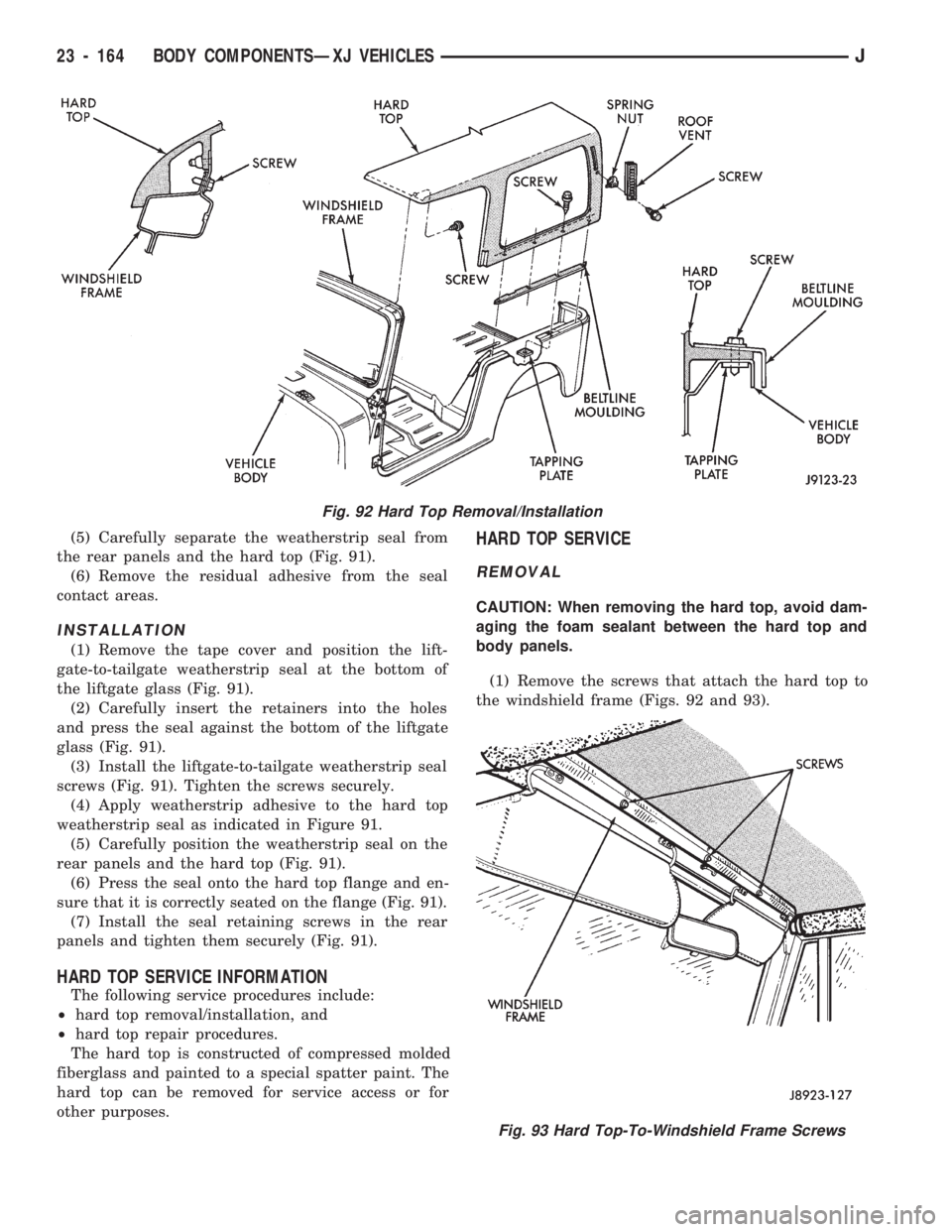
(5) Carefully separate the weatherstrip seal from
the rear panels and the hard top (Fig. 91).
(6) Remove the residual adhesive from the seal
contact areas.
INSTALLATION
(1) Remove the tape cover and position the lift-
gate-to-tailgate weatherstrip seal at the bottom of
the liftgate glass (Fig. 91).
(2) Carefully insert the retainers into the holes
and press the seal against the bottom of the liftgate
glass (Fig. 91).
(3) Install the liftgate-to-tailgate weatherstrip seal
screws (Fig. 91). Tighten the screws securely.
(4) Apply weatherstrip adhesive to the hard top
weatherstrip seal as indicated in Figure 91.
(5) Carefully position the weatherstrip seal on the
rear panels and the hard top (Fig. 91).
(6) Press the seal onto the hard top flange and en-
sure that it is correctly seated on the flange (Fig. 91).
(7) Install the seal retaining screws in the rear
panels and tighten them securely (Fig. 91).
HARD TOP SERVICE INFORMATION
The following service procedures include:
²hard top removal/installation, and
²hard top repair procedures.
The hard top is constructed of compressed molded
fiberglass and painted to a special spatter paint. The
hard top can be removed for service access or for
other purposes.
HARD TOP SERVICE
REMOVAL
CAUTION: When removing the hard top, avoid dam-
aging the foam sealant between the hard top and
body panels.
(1) Remove the screws that attach the hard top to
the windshield frame (Figs. 92 and 93).
Fig. 92 Hard Top Removal/Installation
Fig. 93 Hard Top-To-Windshield Frame Screws
23 - 164 BODY COMPONENTSÐXJ VEHICLESJ
Page 1623 of 1784
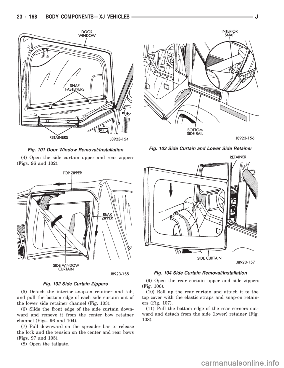
(4) Open the side curtain upper and rear zippers
(Figs. 96 and 102).
(5) Detach the interior snap-on retainer and tab,
and pull the bottom edge of each side curtain out of
the lower side retainer channel (Fig. 103).
(6) Slide the front edge of the side curtain down-
ward and remove it from the center bow retainer
channel (Figs. 96 and 104).
(7) Pull downward on the spreader bar to release
the lock and the tension on the center and rear bows
(Figs. 97 and 105).
(8) Open the tailgate.(9) Open the rear curtain upper and side zippers
(Fig. 106).
(10) Roll up the rear curtain and attach it to the
top cover with the elastic straps and snap-on retain-
ers (Fig. 107).
(11) Pull the bottom edge of the rear corners out-
ward and detach from the side (lower) retainer (Fig.
108).
Fig. 101 Door Window Removal/Installation
Fig. 102 Side Curtain Zippers
Fig. 103 Side Curtain and Lower Side Retainer
Fig. 104 Side Curtain Removal/Installation
23 - 168 BODY COMPONENTSÐXJ VEHICLESJ
Page 1626 of 1784
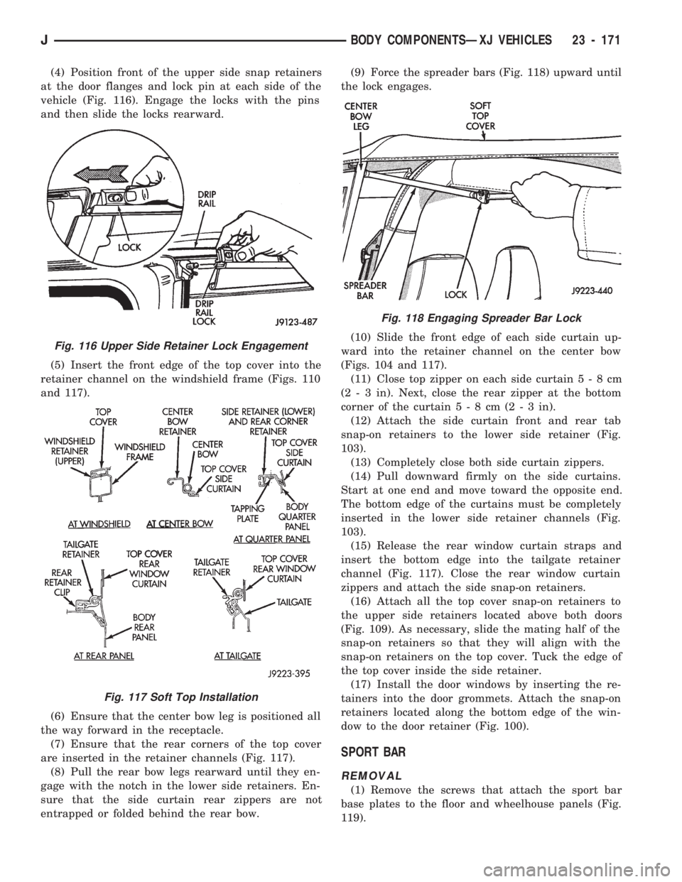
(4) Position front of the upper side snap retainers
at the door flanges and lock pin at each side of the
vehicle (Fig. 116). Engage the locks with the pins
and then slide the locks rearward.
(5) Insert the front edge of the top cover into the
retainer channel on the windshield frame (Figs. 110
and 117).
(6) Ensure that the center bow leg is positioned all
the way forward in the receptacle.
(7) Ensure that the rear corners of the top cover
are inserted in the retainer channels (Fig. 117).
(8) Pull the rear bow legs rearward until they en-
gage with the notch in the lower side retainers. En-
sure that the side curtain rear zippers are not
entrapped or folded behind the rear bow.(9) Force the spreader bars (Fig. 118) upward until
the lock engages.
(10) Slide the front edge of each side curtain up-
ward into the retainer channel on the center bow
(Figs. 104 and 117).
(11) Close top zipper on each side curtain5-8cm
(2 - 3 in). Next, close the rear zipper at the bottom
corner of the curtain5-8cm(2-3in).
(12) Attach the side curtain front and rear tab
snap-on retainers to the lower side retainer (Fig.
103).
(13) Completely close both side curtain zippers.
(14) Pull downward firmly on the side curtains.
Start at one end and move toward the opposite end.
The bottom edge of the curtains must be completely
inserted in the lower side retainer channels (Fig.
103).
(15) Release the rear window curtain straps and
insert the bottom edge into the tailgate retainer
channel (Fig. 117). Close the rear window curtain
zippers and attach the side snap-on retainers.
(16) Attach all the top cover snap-on retainers to
the upper side retainers located above both doors
(Fig. 109). As necessary, slide the mating half of the
snap-on retainers so that they will align with the
snap-on retainers on the top cover. Tuck the edge of
the top cover inside the side retainer.
(17) Install the door windows by inserting the re-
tainers into the door grommets. Attach the snap-on
retainers located along the bottom edge of the win-
dow to the door retainer (Fig. 100).
SPORT BAR
REMOVAL
(1) Remove the screws that attach the sport bar
base plates to the floor and wheelhouse panels (Fig.
119).
Fig. 116 Upper Side Retainer Lock Engagement
Fig. 117 Soft Top Installation
Fig. 118 Engaging Spreader Bar Lock
JBODY COMPONENTSÐXJ VEHICLES 23 - 171
Page 1627 of 1784
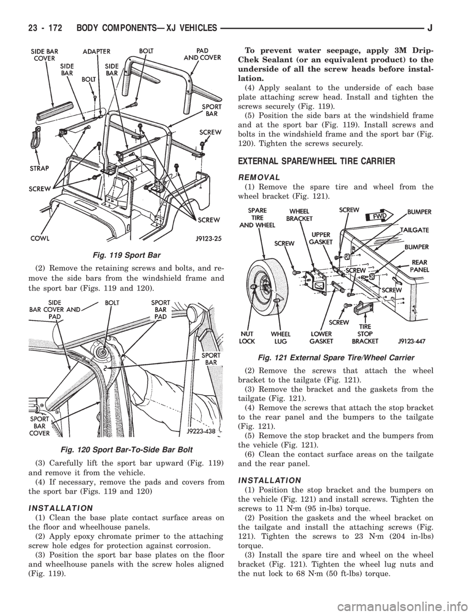
(2) Remove the retaining screws and bolts, and re-
move the side bars from the windshield frame and
the sport bar (Figs. 119 and 120).
(3) Carefully lift the sport bar upward (Fig. 119)
and remove it from the vehicle.
(4) If necessary, remove the pads and covers from
the sport bar (Figs. 119 and 120)
INSTALLATION
(1) Clean the base plate contact surface areas on
the floor and wheelhouse panels.
(2) Apply epoxy chromate primer to the attaching
screw hole edges for protection against corrosion.
(3) Position the sport bar base plates on the floor
and wheelhouse panels with the screw holes aligned
(Fig. 119).To prevent water seepage, apply 3M Drip-
Chek Sealant (or an equivalent product) to the
underside of all the screw heads before instal-
lation.
(4) Apply sealant to the underside of each base
plate attaching screw head. Install and tighten the
screws securely (Fig. 119).
(5) Position the side bars at the windshield frame
and at the sport bar (Fig. 119). Install screws and
bolts in the windshield frame and the sport bar (Fig.
120). Tighten the screws securely.
EXTERNAL SPARE/WHEEL TIRE CARRIER
REMOVAL
(1) Remove the spare tire and wheel from the
wheel bracket (Fig. 121).
(2) Remove the screws that attach the wheel
bracket to the tailgate (Fig. 121).
(3) Remove the bracket and the gaskets from the
tailgate (Fig. 121).
(4) Remove the screws that attach the stop bracket
to the rear panel and the bumpers to the tailgate
(Fig. 121).
(5) Remove the stop bracket and the bumpers from
the vehicle (Fig. 121).
(6) Clean the contact surface areas on the tailgate
and the rear panel.
INSTALLATION
(1) Position the stop bracket and the bumpers on
the vehicle (Fig. 121) and install screws. Tighten the
screws to 11 Nzm (95 in-lbs) torque.
(2) Position the gaskets and the wheel bracket on
the tailgate and install the attaching screws (Fig.
121). Tighten the screws to 23 Nzm (204 in-lbs)
torque.
(3) Install the spare tire and wheel on the wheel
bracket (Fig. 121). Tighten the wheel lug nuts and
the nut lock to 68 Nzm (50 ft-lbs) torque.
Fig. 119 Sport Bar
Fig. 120 Sport Bar-To-Side Bar Bolt
Fig. 121 External Spare Tire/Wheel Carrier
23 - 172 BODY COMPONENTSÐXJ VEHICLESJ