1994 JEEP CHEROKEE tailgate
[x] Cancel search: tailgatePage 35 of 1784
(6) Inspect the disc brake caliper dust boot for cor-
rect installation, damage/tears and indications of
brake fluid leakage. Inspect the bushings and pins
for corrosion, tears and a binding condition.
(7) Pull the rear wheel cylinder dust boot back to
expose the wheel cylinder housing and inspect for
fluid leaks. Inspect the pistons and cylinder bores for
proper appearance.
(8) Inspect the brake differential warning valve
and housing for indications of leakage, kinked hoses
and loose fittings.
PARK BRAKE
(1) As applicable, engage the park brake lever or
pedal and then release it.
(2) If the park brake is functioning normally, test
it for smooth operation and vehicle-holding capabil-
ity.
(3) Inspect the park brake cables for kinks, fraying
and a binding condition.
(4) With the park brake released, the rear wheels
should rotate without restriction. Adjust the park
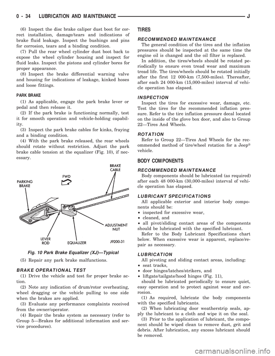
brake cable tension at the equalizer (Fig. 10), if nec-
essary.
(5) Repair any park brake malfunctions.
BRAKE OPERATIONAL TEST
(1) Drive the vehicle and test for proper brake ac-
tion.
(2) Note any indication of drum/rotor overheating,
wheel dragging or the vehicle pulling to one side
when the brakes are applied.
(3) Evaluate any performance complaints received
from the owner/operator.
(4) Repair the brake system as necessary (refer to
Group 5ÐBrakes for additional information and ser-
vice procedures).
TIRES
RECOMMENDED MAINTENANCE
The general condition of the tires and the inflation
pressures should be inspected at the same time the
engine oil is changed and the oil filter is replaced.
In addition, the tires/wheels should be rotated pe-
riodically to ensure even tread wear and maximum
tread life. The tires/wheels should be rotated initially
after the first 12 000-km (7,500-miles). Thereafter,
after each 24 000-km (15,000-miles) interval of vehi-
cle operation has elapsed.
INSPECTION
Inspect the tires for excessive wear, damage, etc.
Test the tires for the recommended inflation pres-
sure. Refer to the tire inflation pressure decal located
on the inside of the glove box door, and also to Group
22ÐTires And Wheels.
ROTATION
Refer to Group 22ÐTires And Wheels for the rec-
ommended method of tire/wheel rotation for a Jeept
vehicle.
BODY COMPONENTS
RECOMMENDED MAINTENANCE
Body components should be lubricated (as required)
after each 48 000-km (30,000-miles) interval of vehi-
cle operation has elapsed.
LUBRICANT SPECIFICATIONS
All applicable exterior and interior body compo-
nents should be:
²inspected for excessive wear,
²cleaned, and
²all pivot/sliding contact areas of the components
should be lubricated with the specified lubricant.
Refer to the Body Lubricant Specifications chart
below. When excessive wear is apparent, replace/re-
pair as necessary.
LUBRICATION
All pivoting and sliding contact areas, including:
²seat tracks,
²door hinges/latches/strikers, and
²liftgate/tailgate/hood hinges (Fig. 11),
should be lubricated periodically to ensure quiet,
easy operation and to protect against wear and cor-
rosion.
(1) As required, lubricate the body components
with the specified lubricants.
(2) When lubricating door weatherstrip seals, ap-
ply the lubricant to a cloth and wipe it on the seal.
(3) Prior to the application of lubricant, the compo-
nent should be wiped clean to remove dust, grit and
debris. After lubrication, any excess lubricant should
be removed.
Fig. 10 Park Brake Equalizer (XJ)ÐTypical
0 - 34 LUBRICATION AND MAINTENANCEJ
Page 959 of 1784
(2) Install the screws that attach the bracket to
the frame rail. Tighten the screws to 42 Nzm (31 ft-
lbs) torque.
(3) Install the fuel filter in the bracket.
(4) Position the clamp on the bracket and install
bolt and nut. Tighten the nut to 8 Nzm (72 in-lbs)
torque.
(5) Position the fuel filter shield from the frame
rail.
(6) Install the screws that attach the fuel filter
shield to the frame rail. Tighten the screws to 42
Nzm (31 ft-lbs) torque.
REAR JOUNCE BUMPER
REMOVAL
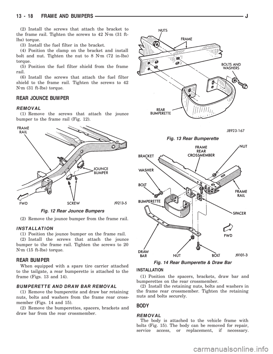
(1) Remove the screws that attach the jounce
bumper to the frame rail (Fig. 12).
(2) Remove the jounce bumper from the frame rail.
INSTALLATION
(1) Position the jounce bumper on the frame rail.
(2) Install the screws that attach the jounce
bumper to the frame rail. Tighten the screws to 20
Nzm (15 ft-lbs) torque.
REAR BUMPER
When equipped with a spare tire carrier attached
to the tailgate, a rear bumperette is attached to the
frame (Figs. 13 and 14).
BUMPERETTE AND DRAW BAR REMOVAL
(1) Remove the bumperette and draw bar retaining
nuts, bolts and washers from the frame rear cross-
member (Figs. 14 and 15).
(2) Remove the bumperettes, spacers, brackets and
draw bar from the rear crossmember.INSTALLATION
(1) Position the spacers, brackets, draw bar and
bumperettes on the rear crossmember.
(2) Install the retaining nuts, bolts and washers in
the frame rear crossmember. Tighten the retaining
nuts and bolts securely.
BODY
REMOVAL
The body is attached to the vehicle frame with
bolts (Fig. 15). The body can be removed for repair,
service access, or replacement, if necessary.
Fig. 12 Rear Jounce Bumpers
Fig. 13 Rear Bumperette
Fig. 14 Rear Bumperette & Draw Bar
13 - 18 FRAME AND BUMPERSJ
Page 1476 of 1784
LIFTGATE UPPER MOULDING
REMOVAL
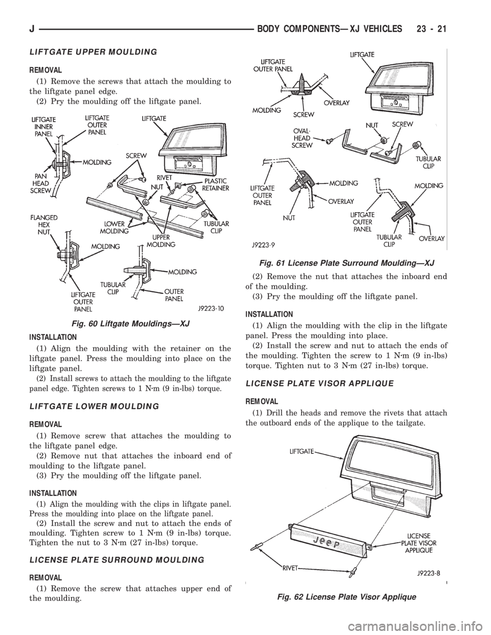
(1) Remove the screws that attach the moulding to
the liftgate panel edge.
(2) Pry the moulding off the liftgate panel.
INSTALLATION
(1) Align the moulding with the retainer on the
liftgate panel. Press the moulding into place on the
liftgate panel.
(2) Install screws to attach the moulding to the liftgate
panel edge. Tighten screws to 1 Nzm (9 in-lbs) torque.
LIFTGATE LOWER MOULDING
REMOVAL
(1) Remove screw that attaches the moulding to
the liftgate panel edge.
(2) Remove nut that attaches the inboard end of
moulding to the liftgate panel.
(3) Pry the moulding off the liftgate panel.
INSTALLATION
(1) Align the moulding with the clips in liftgate panel.
Press the moulding into place on the liftgate panel.
(2) Install the screw and nut to attach the ends of
moulding. Tighten screw to 1 Nzm (9 in-lbs) torque.
Tighten the nut to 3 Nzm (27 in-lbs) torque.
LICENSE PLATE SURROUND MOULDING
REMOVAL
(1) Remove the screw that attaches upper end of
the moulding.(2) Remove the nut that attaches the inboard end
of the moulding.
(3) Pry the moulding off the liftgate panel.
INSTALLATION
(1) Align the moulding with the clip in the liftgate
panel. Press the moulding into place.
(2) Install the screw and nut to attach the ends of
the moulding. Tighten the screw to 1 Nzm (9 in-lbs)
torque. Tighten nut to 3 Nzm (27 in-lbs) torque.
LICENSE PLATE VISOR APPLIQUE
REMOVAL
(1) Drill the heads and remove the rivets that attach
the outboard ends of the applique to the tailgate.
Fig. 61 License Plate Surround MouldingÐXJ
Fig. 62 License Plate Visor Applique
Fig. 60 Liftgate MouldingsÐXJ
JBODY COMPONENTSÐXJ VEHICLES 23 - 21
Page 1477 of 1784
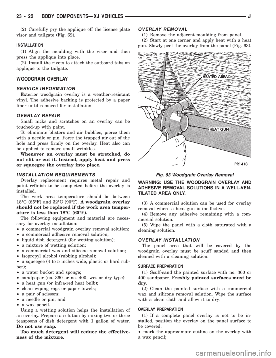
(2) Carefully pry the applique off the license plate
visor and tailgate (Fig. 62).
INSTALLATION
(1) Align the moulding with the visor and then
press the applique into place.
(2) Install the rivets to attach the outboard tabs on
applique to the tailgate.
WOODGRAIN OVERLAY
SERVICE INFORMATION
Exterior woodgrain overlay is a weather-resistant
vinyl. The adhesive backing is protected by a paper
liner until removed for installation.
OVERLAY REPAIR
Small nicks and scratches on an overlay can be
touched-up with paint.
To eliminate blisters and air bubbles, pierce them
with a needle or pin. Force the trapped air out of the
hole and press firmly on the overlay. Heat also can
be applied to remove small wrinkles.
Whenever an overlay must be stretched, do
not slit or cut it. Instead, apply heat and press
or squeegee the overlay into place.
INSTALLATION REQUIREMENTS
Overlay replacement requires metal repair and
paint refinish to be completed before the overlay is
installed.
The work area temperature should be between
18ÉC (65ÉF) and 32ÉC (90ÉF).A woodgrain overlay
should not be replaced if the work area temper-
ature is less than 18ÉC (65ÉF).
The following equipment and material are neces-
sary for overlay installation:
²a commercial woodgrain overlay removal solution;
²a commercial adhesive removal solution;
²liquid dish detergent (for wetting solution);
²a mixture of wetting solution;
²a commercial wax and silicone removal solution;
²isopropyl alcohol (rubbing alcohol);
²a squeegee (4 to 5 inches wide, plastic or hard rub-
ber);
²a water bucket and sponge;
²sandpaper (no. 360 or no. 400, wet or dry type);
²a heat gun (or infra-red heat bulb);
²clean wiping rags or paper towels;
²a pair of scissors;
²a needle or pin; and
²a wax pencil.
Using a wetting solution helps the installation of
an overlay. Prepare a solution by mixing two or three
teaspoons of dish detergent with 1 gallon of water.
Do not use soap.
Too much detergent will reduce the effective-
ness of the mixture.
OVERLAY REMOVAL
(1) Remove the adjacent moulding from panel.
(2) Start at one corner and apply heat with a heat
gun. Slowly peel the overlay from the panel (Fig. 63).
WARNING: USE THE WOODGRAIN OVERLAY AND
ADHESIVE REMOVAL SOLUTIONS IN A WELL-VEN-
TILATED AREA ONLY.
(3) A commercial solution can be used for overlay
removal where a heat gun is ineffective.
(4) Remove any adhesive remaining with a com-
mercial solution.
(5) Wipe the panel with a cloth saturated with a
cleaning solution.
OVERLAY INSTALLATION
The panel area that will be covered by the
woodgrain overlay must be scuff sanded and then
cleaned with a cleaning solution.
SURFACE PREPARATION
(1) Scuff-sand the painted surface with no. 360 or
400 sandpaper.Freshly painted surfaces must be
dry.
(2) Clean the painted surface with a commercial
wax and silicone removal solution. Wipe the surface
with a clean cloth and allow it to dry.
OVERLAY PREPARATION
(1) If a complete panel overlay is not to be in-
stalled, position the overlay on the panel surface to
be covered:
²mark the approximate outline on the overlay with
a wax pencil;
Fig. 63 Woodgrain Overlay Removal
23 - 22 BODY COMPONENTSÐXJ VEHICLESJ
Page 1484 of 1784
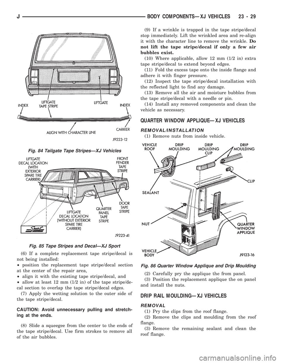
(6) If a complete replacement tape stripe/decal is
not being installed:
²position the replacement tape stripe/decal section
at the center of the repair area,
²align it with the existing tape stripe/decal, and
²allow at least 12 mm (1/2 in) of the tape stripe/de-
cal section to overlap the tape stripe/decal edges.
(7) Apply the wetting solution to the outer side of
the tape stripe/decal.
CAUTION: Avoid unnecessary pulling and stretch-
ing at the ends.
(8) Slide a squeegee from the center to the ends of
the tape stripe/decal. Use firm strokes to remove all
of the air bubbles.(9) If a wrinkle is trapped in the tape stripe/decal
stop immediately. Lift the wrinkled area and re-align
it with the character line to remove the wrinkle.Do
not lift the tape stripe/decal if only a few air
bubbles exist.
(10) Where applicable, allow 12 mm (1/2 in) extra
tape stripe/decal to extend beyond edges.
(11) Fold the excess tape onto the inside flange and
adhere it with finger pressure.
(12) Inspect the tape stripe/decal installation with
the reflected light to find any damage.
(13) Remove all the air and moisture bubbles from
the tape stripe/decal with a needle or pin.
(14) Install any removed components and clean the
vehicle as necessary.
QUARTER WINDOW APPLIQUEÐXJ VEHICLES
REMOVAL/INSTALLATION
(1) Remove nuts from inside vehicle.
(2) Carefully pry the applique the from panel.
(3) Position the replacement applique the on panel
and install the nuts.
DRIP RAIL MOULDINGÐXJ VEHICLES
REMOVAL
(1) Pry the clips from the roof flange.
(2) Remove the clips and moulding from the roof
flange.
(3) Remove the remaining sealant and clean the
roof flange.
Fig. 84 Tailgate Tape StripesÐXJ Vehicles
Fig. 85 Tape Stripes and DecalÐXJ Sport
Fig. 86 Quarter Window Applique and Drip Moulding
JBODY COMPONENTSÐXJ VEHICLES 23 - 29
Page 1587 of 1784
BODY COMPONENTSÐYJ VEHICLES
CONTENTS
page page
ADD-A-TRUNK........................ 198
DOORS.............................. 172
EXTERIOR COMPONENTS............... 134FIXED WINDOW GLASS................ 181
GENERAL SERVICE INFORMATION........ 132
INTERIOR COMPONENTS............... 188
GENERAL SERVICE INFORMATION
LABELS/DECALS/PLATES
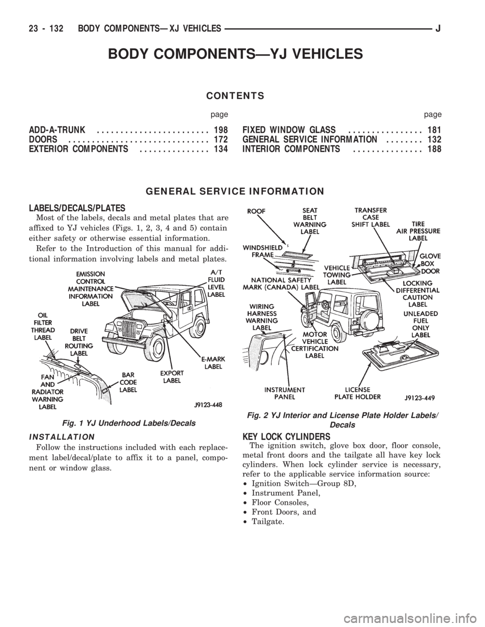
Most of the labels, decals and metal plates that are
affixed to YJ vehicles (Figs. 1, 2, 3, 4 and 5) contain
either safety or otherwise essential information.
Refer to the Introduction of this manual for addi-
tional information involving labels and metal plates.
INSTALLATION
Follow the instructions included with each replace-
ment label/decal/plate to affix it to a panel, compo-
nent or window glass.
KEY LOCK CYLINDERS
The ignition switch, glove box door, floor console,
metal front doors and the tailgate all have key lock
cylinders. When lock cylinder service is necessary,
refer to the applicable service information source:
²Ignition SwitchÐGroup 8D,
²Instrument Panel,
²Floor Consoles,
²Front Doors, and
²Tailgate.
Fig. 1 YJ Underhood Labels/DecalsFig. 2 YJ Interior and License Plate Holder Labels/
Decals
23 - 132 BODY COMPONENTSÐXJ VEHICLESJ
Page 1589 of 1784
EXTERIOR COMPONENTS
INDEX
page page
Battery Tray........................... 140
Body Extension Panels and FasciasÐYJ
Renegade Vehicles..................... 147
Body Side Step Moulding................. 145
Body Stripes/Decals..................... 153
Cowl Grille and Screen................... 139
Cowl Weatherstrip Seal................... 139
Exterior Nameplates (Adhesive-Backed)....... 158
External Spare/Wheel Tire Carrier........... 172
Fender Flare........................... 144
Fender Inner Splash Shields............... 147
Fender Splash Aprons.................... 147
Fenders............................... 141
Fog LampÐYJ Renegade Vehicles.......... 150
Front Fascia and Skid PlateÐYJ Renegade
Vehicles............................. 148
Front Fender Extension PanelÐYJ Renegade
Vehicles............................. 149
Fuel Filler Protector/Nozzle................ 158
Half Metal Door Mirror (External)............ 158
Hard Top Liftgate Glass.................. 162
Hard Top Repair........................ 165
Hard Top Roof Vent..................... 165
Hard Top Service....................... 164
Hard Top Service Information.............. 164Hood................................. 137
Hood Alignment......................... 138
Hood Insulator Panel..................... 138
Hood Safety Latch....................... 139
Liftgate Glass Weatherstrip Seal Replacement . . 163
Radiator Grille Applique................... 134
Rear Fascia and Skid PlateÐYJ Renegade
Vehicles............................. 152
Rear Quarter Extension PanelÐYJ Renegade
Vehicles............................. 151
Rocker Extension PanelÐYJ Renegade
Vehicles............................. 150
Soft Top Service........................ 167
Soft Top Service Information............... 166
Sport Bar............................. 171
Tailgate Adjustment...................... 160
Tailgate Hinge.......................... 159
Tailgate Latch and Release Handle.......... 160
Tailgate Latch Striker..................... 161
Tailgate Lock Cylinder.................... 160
Tailgate Service......................... 159
Tailgate Service Information................ 159
Tailgate Weatherstrip Seal................. 161
Wheelhouse Splash Liners................ 146
RADIATOR GRILLE APPLIQUE
REMOVAL
(1) Raise the hood.
(2) Remove the headlamp bezels (Fig. 1).
(3) Remove the headlamp bulb retainer screws
(Fig. 2).
(4) Disconnect and remove the headlamps and
buckets as a unit (Fig. 2).
(5) Remove the parking lamp retaining screws
(Fig. 2).
(6) Disconnect the wire harness connectors and re-
move the parking lamps (Fig. 2).
(7) Remove the front crossmember cover.
(8) Remove the retaining screws and the bumper
inserts at the top of the grille panel (Fig. 1).
(9) Detach the grille applique from the grille panel
(Fig. 1).
(10) Remove the double faced foam adhesive tape
at the bottom of the grille applique (Fig. 1).
INSTALLATION
(1) Install double faced foam tape at the bottom,
interior side of the grille applique (Fig. 1).
(2) Position the grille applique over the grille
panel and press inward along the bottom where the
tape is located (Fig. 1).
(3) Install the grille applique retaining screws and
the bumper inserts (Fig. 1).(4) Connect the wire harness connectors and posi-
tion the headlamp buckets and headlamps in the
grille panel (Fig. 2).
(5) Install the headlamp bulb retainer and the
screws (Fig. 1). Tighten the screws to 2 Nzm (18 in-
lbs) torque.
(6) Install the headlamp bezels and the retaining
screws (Fig. 1). Tighten the screws securely.
(7) Connect the wire harness connectors and in-
stall the parking lamps (Fig. 2).
(8) Install the parking lamp retaining screws.
Tighten the screws to 2 Nzm (18 in-lbs) torque.
(9) Close the hood.
(10) Install the front crossmember cover.
23 - 134 BODY COMPONENTSÐXJ VEHICLESJ
Page 1614 of 1784
(2) Remove the mirror from the door hinge (Fig.
78).
INSTALLATION
(1) Clean the door hinge-mirror base contact sur-
face.
(2) Position the mirror base at the door hinge (Fig.
78).
(3) Install the mirror base attaching screws in the
door hinge (Fig. 78). Tighten the attaching screws to
11 Nzm (96 in-lbs) torque.
TAILGATE SERVICE INFORMATION
The following tailgate service procedures include:
²tailgate removal/installation,
²tailgate hinge replacement,
²tailgate adjustment,
²tailgate latch removal/installation,
²tailgate lock cylinder removal/installation,
²tailgate latch striker removal/installation, and
²tailgate seal replacement.
TAILGATE SERVICE
REMOVAL
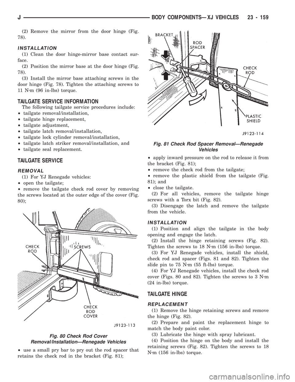
(1) For YJ Renegade vehicles:
²open the tailgate;
²remove the tailgate check rod cover by removing
the screws located at the outer edge of the cover (Fig.
80);
²use a small pry bar to pry out the rod spacer that
retains the check rod in the bracket (Fig. 81);²apply inward pressure on the rod to release it from
the bracket (Fig. 81);
²remove the check rod from the tailgate;
²remove the plastic shield from the tailgate (Fig.
81); and
²close the tailgate.
(2) For all vehicles, remove the tailgate hinge
screws with a Torx bit (Fig. 82).
(3) Disengage the latch and remove the tailgate
from the vehicle.
INSTALLATION
(1) Position and align the tailgate in the body
opening and engage the latch.
(2) Install the hinge retaining screws (Fig. 82).
Tighten the screws to 18 Nzm (156 in-lbs) torque.
(3) For YJ Renegade vehicles, install the shield,
check rod and spacer (Figs. 81 and 82). Tighten the
slide pin to 75 Nzm (55 ft-lbs) torque.
(4) For YJ Renegade vehicles, install the check rod
cover (Figs. 80 and 82). Tighten the screws to 3 Nzm
(24 in-lbs) torque.
TAILGATE HINGE
REPLACEMENT
(1) Remove the hinge retaining screws and remove
the hinge (Fig. 82).
(2) Prepare and paint the replacement hinge to
match the body paint color.
(3) Lubricate the hinge with spray lubricant.
(4) Position the hinge on the body and install the
retaining screws (Fig. 82). Tighten the screws to 18
Nzm (156 in-lbs) torque.
Fig. 80 Check Rod Cover
Removal/InstallationÐRenegade Vehicles
Fig. 81 Check Rod Spacer RemovalÐRenegade
Vehicles
JBODY COMPONENTSÐXJ VEHICLES 23 - 159