1994 JEEP CHEROKEE belt
[x] Cancel search: beltPage 131 of 1784
IDLE AIR CONTROL MOTOR TEST
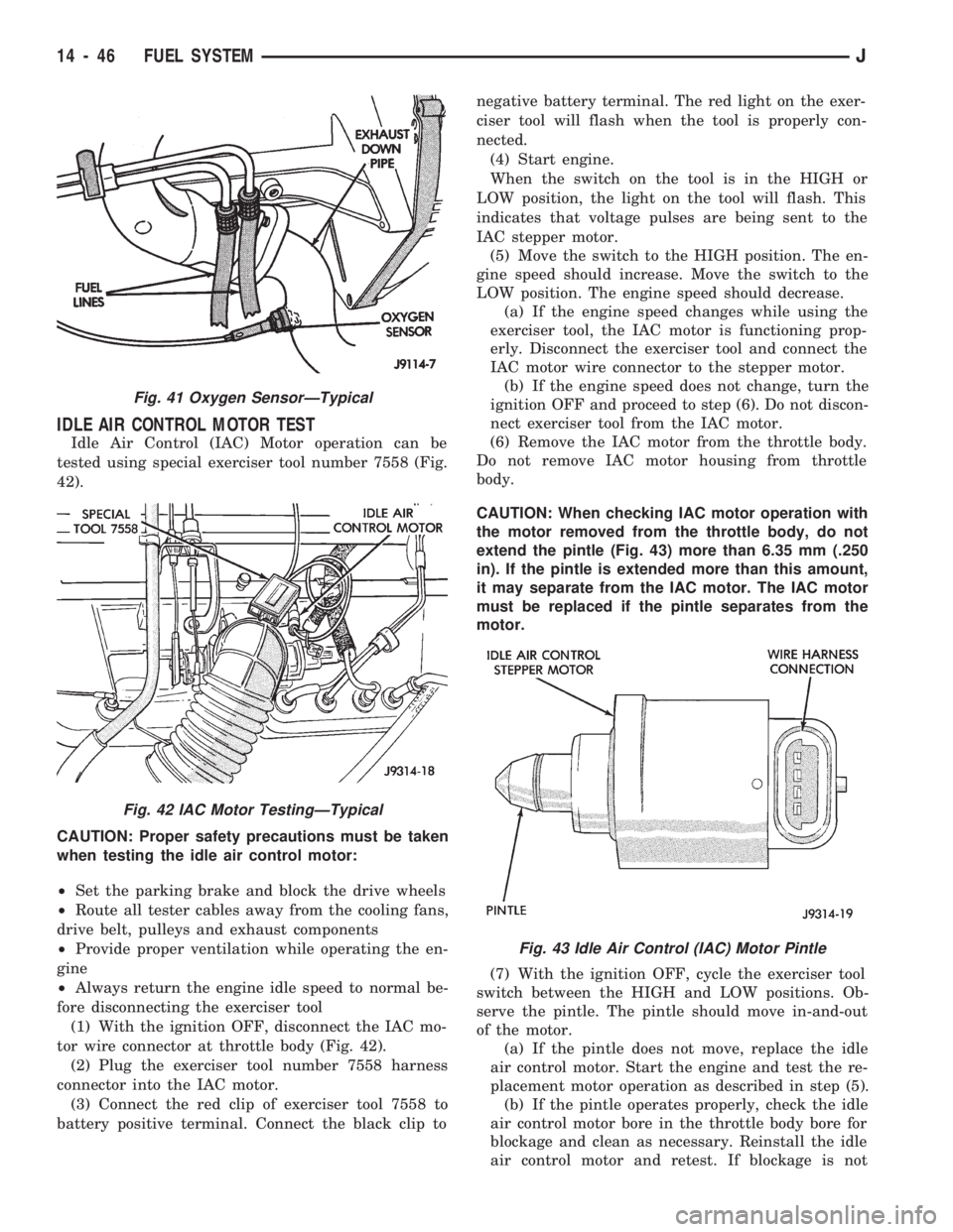
Idle Air Control (IAC) Motor operation can be
tested using special exerciser tool number 7558 (Fig.
42).
CAUTION: Proper safety precautions must be taken
when testing the idle air control motor:
²Set the parking brake and block the drive wheels
²Route all tester cables away from the cooling fans,
drive belt, pulleys and exhaust components
²Provide proper ventilation while operating the en-
gine
²Always return the engine idle speed to normal be-
fore disconnecting the exerciser tool
(1) With the ignition OFF, disconnect the IAC mo-
tor wire connector at throttle body (Fig. 42).
(2) Plug the exerciser tool number 7558 harness
connector into the IAC motor.
(3) Connect the red clip of exerciser tool 7558 to
battery positive terminal. Connect the black clip tonegative battery terminal. The red light on the exer-
ciser tool will flash when the tool is properly con-
nected.
(4) Start engine.
When the switch on the tool is in the HIGH or
LOW position, the light on the tool will flash. This
indicates that voltage pulses are being sent to the
IAC stepper motor.
(5) Move the switch to the HIGH position. The en-
gine speed should increase. Move the switch to the
LOW position. The engine speed should decrease.
(a) If the engine speed changes while using the
exerciser tool, the IAC motor is functioning prop-
erly. Disconnect the exerciser tool and connect the
IAC motor wire connector to the stepper motor.
(b) If the engine speed does not change, turn the
ignition OFF and proceed to step (6). Do not discon-
nect exerciser tool from the IAC motor.
(6) Remove the IAC motor from the throttle body.
Do not remove IAC motor housing from throttle
body.
CAUTION: When checking IAC motor operation with
the motor removed from the throttle body, do not
extend the pintle (Fig. 43) more than 6.35 mm (.250
in). If the pintle is extended more than this amount,
it may separate from the IAC motor. The IAC motor
must be replaced if the pintle separates from the
motor.
(7) With the ignition OFF, cycle the exerciser tool
switch between the HIGH and LOW positions. Ob-
serve the pintle. The pintle should move in-and-out
of the motor.
(a) If the pintle does not move, replace the idle
air control motor. Start the engine and test the re-
placement motor operation as described in step (5).
(b) If the pintle operates properly, check the idle
air control motor bore in the throttle body bore for
blockage and clean as necessary. Reinstall the idle
air control motor and retest. If blockage is not
Fig. 41 Oxygen SensorÐTypical
Fig. 42 IAC Motor TestingÐTypical
Fig. 43 Idle Air Control (IAC) Motor Pintle
14 - 46 FUEL SYSTEMJ
Page 234 of 1784
COOLING SYSTEM
CONTENTS
page page
DIAGNOSIS............................. 4
ENGINE ACCESSORY DRIVE BELTS........ 31
ENGINE BLOCK HEATER................. 37GENERAL INFORMATION.................. 1
SERVICE PROCEDURES................... 9
SPECIFICATIONS....................... 38
GENERAL INFORMATION
Throughout this group, references are made to par-
ticular vehicle models by alphabetical designation
(XJ or YJ) or by the particular vehicle nameplate. A
chart showing a breakdown of alphabetical designa-
tions is included in the Introduction section at the
beginning of this manual.
COOLING SYSTEM
The cooling system regulates engine operating tem-
perature. It allows the engine to reach normal oper-
ating temperature as quickly as possible, maintains
normal operating temperature and prevents over-
heating.
The cooling system also provides a means of heat-
ing the passenger compartment and cooling the auto-
matic transmission fluid (if equipped). The cooling
system is pressurized and uses a centrifugal water
pump to circulate coolant throughout the system.
An optional factory installed heavy duty cooling
package is available on most models. The package
consists of a radiator that has an increased numberof cooling fins. XJ models equipped with a 4.0L 6 cyl-
inder engine and heavy duty cooling and/or air con-
ditioning also have an auxiliary electric cooling fan.
COOLING SYSTEM COMPONENTS
The cooling system consists of:
²A radiator
²Cooling fan (mechanical and/or electrical)
²Thermal viscous fan drive
²Fan shroud
²Radiator pressure cap
²Thermostat
²Coolant reserve/overflow system
²Transmission oil cooler (if equipped with an auto-
matic transmission)
²Coolant
²Water pump
²Hoses and hose clamps
SYSTEM COOLANT ROUTING
For cooling system flow routings, refer to Figs. 1, 2,
3or4.
JCOOLING SYSTEM 7 - 1
Page 238 of 1784
ERASING TROUBLE CODES
After the problem has been repaired, the DRB scan
tool must be used to erase a DTC. Refer to the ap-
propriate Powertrain Diagnostic Procedures service
manual for operation of the DRB scan tool.
DRB SCAN TOOL
For operation of the DRB scan tool, refer to the ap-
propriate Powertrain Diagnostic Procedures service
manual.
PRELIMINARY CHECKS
ENGINE COOLING SYSTEM OVERHEATING
Establish what driving conditions caused the com-
plaint. Abnormal loads on the cooling system such as
the following may be the cause.
1. PROLONGED IDLE, VERY HIGH AMBI-
ENT TEMPERATURE, SLIGHT TAIL WIND AT
IDLE, SLOW TRAFFIC, TRAFFIC JAMS, HIGH
SPEED, OR STEEP GRADES:
Driving techniques that avoid overheating are:
²Idle with A/C off when temperature gauge is at
end of normal range.
²Increasing engine speed for more air flow is recom-
mended.2. TRAILER TOWING:
Consult Trailer Towing section of owners manual.
Do not exceed limits.
3. AIR CONDITIONING; ADD-ON OR AFTER
MARKET:
A maximum cooling package should have been or-
dered with vehicle if add-on or after market A/C is
installed. If not, maximum cooling system compo-
nents should be installed for model involved per
manufacturer's specifications.
4. RECENT SERVICE OR ACCIDENT RE-
PAIR:
Determine if any recent service has been performed
on vehicle that may effect cooling system. This may
be:
²Engine adjustments (incorrect timing)
²Slipping engine accessory drive belt(s)
²Brakes (possibly dragging)
²Changed parts (incorrect water pump rotating in
wrong direction)
²Reconditioned radiator or cooling system refilling
(possibly under-filled or air trapped in system).
If investigation reveals none of the above as a
cause for engine overheating complaint, refer to fol-
lowing Symptom and Action chart.
JCOOLING SYSTEM 7 - 5
Page 242 of 1784
SERVICE PROCEDURES
INDEX
page page
Coolant................................ 15
Coolant Reserve/Overflow System............ 19
Cooling System Cleaning/Reverse Flushing..... 17
Cooling System Fans..................... 26
Cooling System Hoses.................... 26
Draining Cooling System................... 16
Radiator Pressure Cap.................... 20
Radiators............................... 22Refilling Cooling System................... 17
Testing Cooling System for Leaks............ 18
Thermostat............................. 13
Transmission Oil Coolers................... 29
Water Pump Tests........................ 9
Water PumpsÐGeneral Information............ 9
Water PumpsÐRemoval/Installation........... 10
WATER PUMPSÐGENERAL INFORMATION
A centrifugal water pump circulates coolant
through the water jackets, passages, intake manifold,
radiator core, cooling system hoses and heater core.
The pump is driven from the engine crankshaft by a
drive belt on all engines.
The water pump impeller is pressed onto the rear
of a shaft that rotates in bearings pressed into the
housing. The housing has a small hole to allow seep-
age to escape. The water pump seals are lubricated
by the antifreeze in the coolant mixture. No addi-
tional lubrication is necessary.
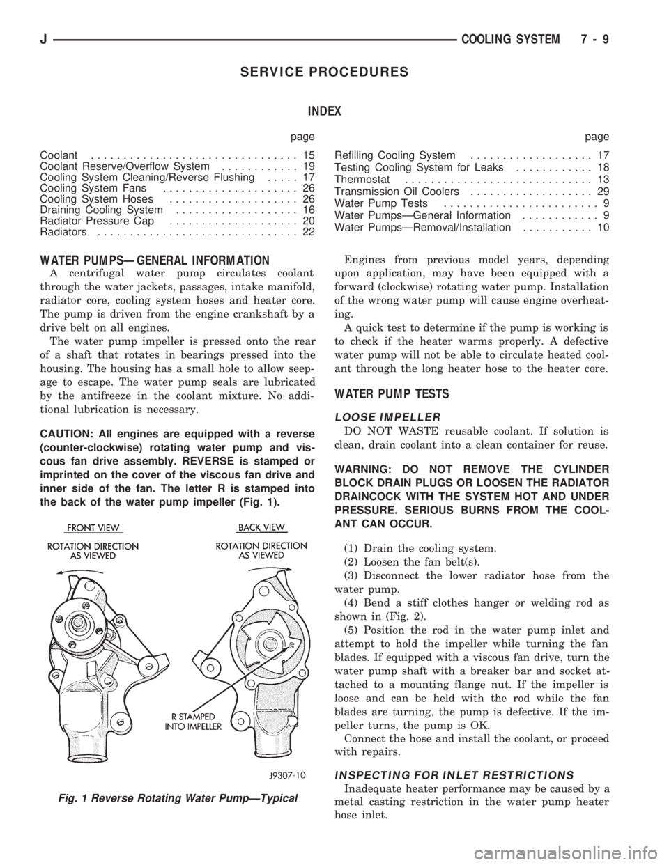
CAUTION: All engines are equipped with a reverse
(counter-clockwise) rotating water pump and vis-
cous fan drive assembly. REVERSE is stamped or
imprinted on the cover of the viscous fan drive and
inner side of the fan. The letter R is stamped into
the back of the water pump impeller (Fig. 1).Engines from previous model years, depending
upon application, may have been equipped with a
forward (clockwise) rotating water pump. Installation
of the wrong water pump will cause engine overheat-
ing.
A quick test to determine if the pump is working is
to check if the heater warms properly. A defective
water pump will not be able to circulate heated cool-
ant through the long heater hose to the heater core.
WATER PUMP TESTS
LOOSE IMPELLER
DO NOT WASTE reusable coolant. If solution is
clean, drain coolant into a clean container for reuse.
WARNING: DO NOT REMOVE THE CYLINDER
BLOCK DRAIN PLUGS OR LOOSEN THE RADIATOR
DRAINCOCK WITH THE SYSTEM HOT AND UNDER
PRESSURE. SERIOUS BURNS FROM THE COOL-
ANT CAN OCCUR.
(1) Drain the cooling system.
(2) Loosen the fan belt(s).
(3) Disconnect the lower radiator hose from the
water pump.
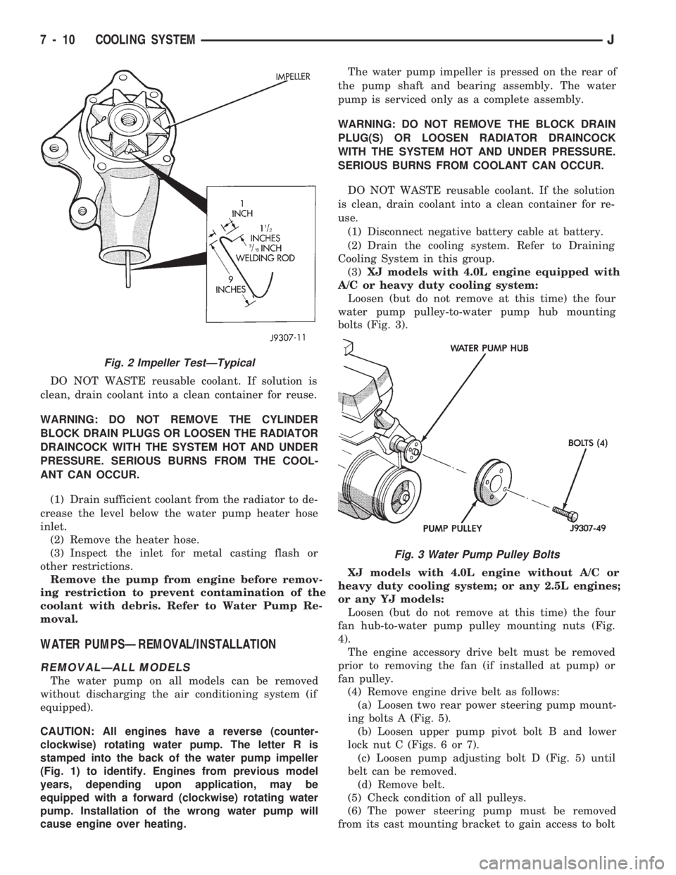
(4) Bend a stiff clothes hanger or welding rod as
shown in (Fig. 2).
(5) Position the rod in the water pump inlet and
attempt to hold the impeller while turning the fan
blades. If equipped with a viscous fan drive, turn the
water pump shaft with a breaker bar and socket at-
tached to a mounting flange nut. If the impeller is
loose and can be held with the rod while the fan
blades are turning, the pump is defective. If the im-
peller turns, the pump is OK.
Connect the hose and install the coolant, or proceed
with repairs.
INSPECTING FOR INLET RESTRICTIONS
Inadequate heater performance may be caused by a
metal casting restriction in the water pump heater
hose inlet.Fig. 1 Reverse Rotating Water PumpÐTypical
JCOOLING SYSTEM 7 - 9
Page 243 of 1784
DO NOT WASTE reusable coolant. If solution is
clean, drain coolant into a clean container for reuse.
WARNING: DO NOT REMOVE THE CYLINDER
BLOCK DRAIN PLUGS OR LOOSEN THE RADIATOR
DRAINCOCK WITH THE SYSTEM HOT AND UNDER
PRESSURE. SERIOUS BURNS FROM THE COOL-
ANT CAN OCCUR.
(1) Drain sufficient coolant from the radiator to de-
crease the level below the water pump heater hose
inlet.
(2) Remove the heater hose.
(3) Inspect the inlet for metal casting flash or
other restrictions.
Remove the pump from engine before remov-
ing restriction to prevent contamination of the
coolant with debris. Refer to Water Pump Re-
moval.
WATER PUMPSÐREMOVAL/INSTALLATION
REMOVALÐALL MODELS
The water pump on all models can be removed
without discharging the air conditioning system (if
equipped).
CAUTION: All engines have a reverse (counter-
clockwise) rotating water pump. The letter R is
stamped into the back of the water pump impeller
(Fig. 1) to identify. Engines from previous model
years, depending upon application, may be
equipped with a forward (clockwise) rotating water
pump. Installation of the wrong water pump will
cause engine over heating.The water pump impeller is pressed on the rear of
the pump shaft and bearing assembly. The water
pump is serviced only as a complete assembly.
WARNING: DO NOT REMOVE THE BLOCK DRAIN
PLUG(S) OR LOOSEN RADIATOR DRAINCOCK
WITH THE SYSTEM HOT AND UNDER PRESSURE.
SERIOUS BURNS FROM COOLANT CAN OCCUR.
DO NOT WASTE reusable coolant. If the solution
is clean, drain coolant into a clean container for re-
use.
(1) Disconnect negative battery cable at battery.
(2) Drain the cooling system. Refer to Draining
Cooling System in this group.
(3)XJ models with 4.0L engine equipped with
A/C or heavy duty cooling system:
Loosen (but do not remove at this time) the four
water pump pulley-to-water pump hub mounting
bolts (Fig. 3).
XJ models with 4.0L engine without A/C or
heavy duty cooling system; or any 2.5L engines;
or any YJ models:
Loosen (but do not remove at this time) the four
fan hub-to-water pump pulley mounting nuts (Fig.
4).
The engine accessory drive belt must be removed
prior to removing the fan (if installed at pump) or
fan pulley.
(4) Remove engine drive belt as follows:
(a) Loosen two rear power steering pump mount-
ing bolts A (Fig. 5).
(b) Loosen upper pump pivot bolt B and lower
lock nut C (Figs. 6 or 7).
(c) Loosen pump adjusting bolt D (Fig. 5) until
belt can be removed.
(d) Remove belt.
(5) Check condition of all pulleys.
(6) The power steering pump must be removed
from its cast mounting bracket to gain access to bolt
Fig. 2 Impeller TestÐTypical
Fig. 3 Water Pump Pulley Bolts
7 - 10 COOLING SYSTEMJ
Page 244 of 1784
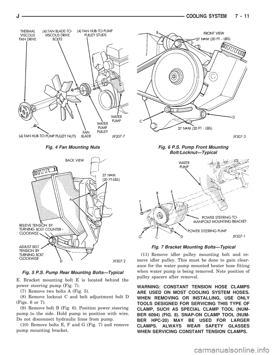
E. Bracket mounting bolt E is located behind the
power steering pump (Fig. 7).
(7) Remove two bolts A (Fig. 5).
(8) Remove locknut C and belt adjustment bolt D
(Figs. 6 or 7).
(9) Remove bolt B (Fig. 6). Position power steering
pump to the side. Hold pump in position with wire.
Do not disconnect hydraulic lines from pump.
(10) Remove bolts E, F and G (Fig. 7) and remove
pump mounting bracket.(11) Remove idler pulley mounting bolt and re-
move idler pulley. This must be done to gain clear-
ance for the water pump mounted heater hose fitting
when water pump is being removed. Note position of
pulley spacers after removal.
WARNING: CONSTANT TENSION HOSE CLAMPS
ARE USED ON MOST COOLING SYSTEM HOSES.
WHEN REMOVING OR INSTALLING, USE ONLY
TOOLS DESIGNED FOR SERVICING THIS TYPE OF
CLAMP, SUCH AS SPECIAL CLAMP TOOL (NUM-
BER 6094) (FIG. 8). SNAP-ON CLAMP TOOL (NUM-
BER HPC-20) MAY BE USED FOR LARGER
CLAMPS. ALWAYS WEAR SAFETY GLASSES
WHEN SERVICING CONSTANT TENSION CLAMPS.
Fig. 4 Fan Mounting Nuts
Fig. 5 P.S. Pump Rear Mounting BoltsÐTypical
Fig. 6 P.S. Pump Front Mounting
Bolt/LocknutÐTypical
Fig. 7 Bracket Mounting BoltsÐTypical
JCOOLING SYSTEM 7 - 11
Page 245 of 1784
CAUTION: A number or letter is stamped into the
tongue of constant tension clamps. If replacement
is necessary, use only an original equipment clamp
with matching number or letter.
(12) Remove lower radiator hose from water pump.
Remove heater hose from water pump fitting.
(13) Remove four nuts or bolts (refer to the previ-
ous step #3).
(14) Remove the fan assembly and pulley (if fan is
installed at pump), or remove the pulley from the ve-
hicle.
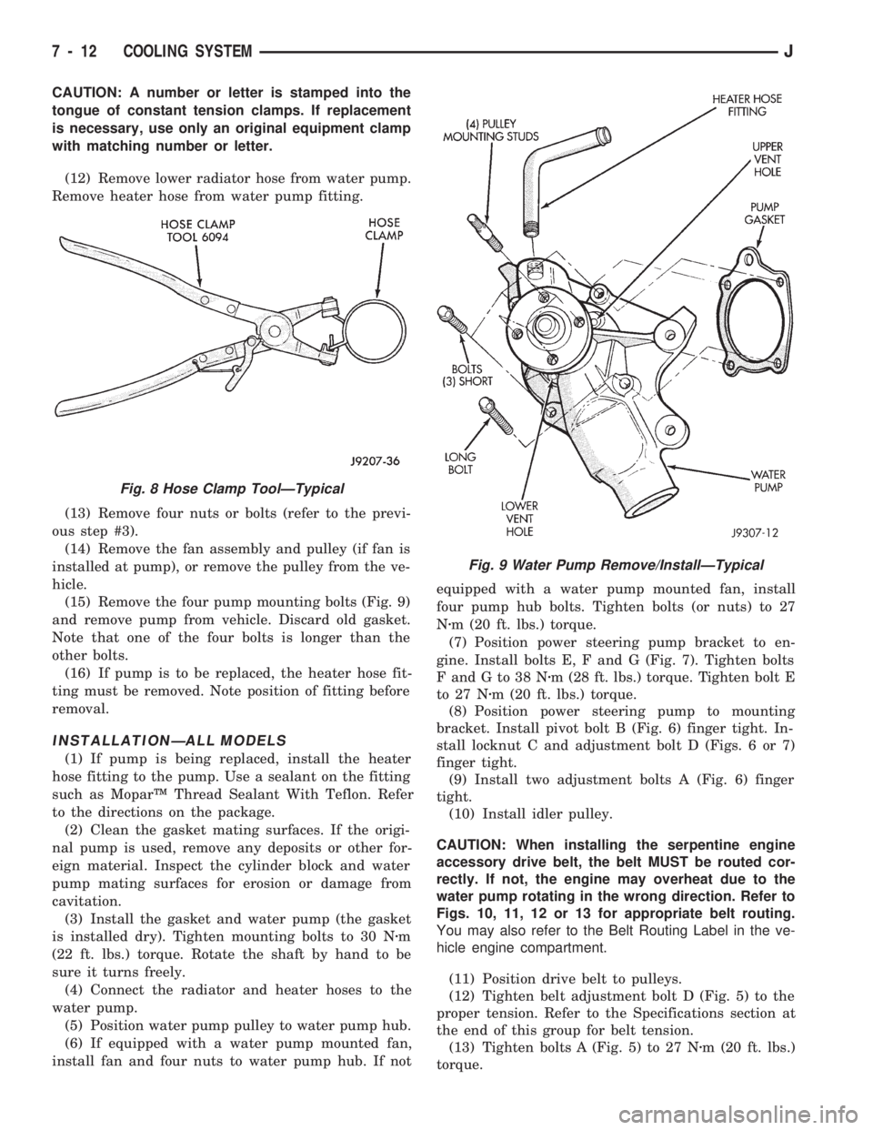
(15) Remove the four pump mounting bolts (Fig. 9)
and remove pump from vehicle. Discard old gasket.
Note that one of the four bolts is longer than the
other bolts.
(16) If pump is to be replaced, the heater hose fit-
ting must be removed. Note position of fitting before
removal.
INSTALLATIONÐALL MODELS
(1) If pump is being replaced, install the heater
hose fitting to the pump. Use a sealant on the fitting
such as MoparŸ Thread Sealant With Teflon. Refer
to the directions on the package.
(2) Clean the gasket mating surfaces. If the origi-
nal pump is used, remove any deposits or other for-
eign material. Inspect the cylinder block and water
pump mating surfaces for erosion or damage from
cavitation.
(3) Install the gasket and water pump (the gasket
is installed dry). Tighten mounting bolts to 30 Nzm
(22 ft. lbs.) torque. Rotate the shaft by hand to be
sure it turns freely.
(4) Connect the radiator and heater hoses to the
water pump.
(5) Position water pump pulley to water pump hub.
(6) If equipped with a water pump mounted fan,
install fan and four nuts to water pump hub. If notequipped with a water pump mounted fan, install
four pump hub bolts. Tighten bolts (or nuts) to 27
Nzm (20 ft. lbs.) torque.
(7) Position power steering pump bracket to en-
gine. Install bolts E, F and G (Fig. 7). Tighten bolts
FandGto38Nzm (28 ft. lbs.) torque. Tighten bolt E
to 27 Nzm (20 ft. lbs.) torque.
(8) Position power steering pump to mounting
bracket. Install pivot bolt B (Fig. 6) finger tight. In-
stall locknut C and adjustment bolt D (Figs. 6 or 7)
finger tight.
(9) Install two adjustment bolts A (Fig. 6) finger
tight.
(10) Install idler pulley.
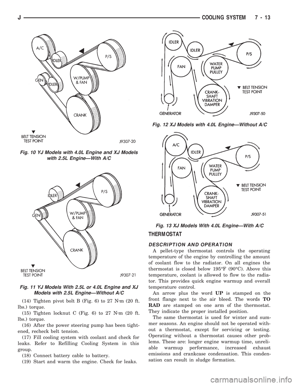
CAUTION: When installing the serpentine engine
accessory drive belt, the belt MUST be routed cor-
rectly. If not, the engine may overheat due to the
water pump rotating in the wrong direction. Refer to
Figs. 10, 11, 12 or 13 for appropriate belt routing.
You may also refer to the Belt Routing Label in the ve-
hicle engine compartment.
(11) Position drive belt to pulleys.
(12) Tighten belt adjustment bolt D (Fig. 5) to the
proper tension. Refer to the Specifications section at
the end of this group for belt tension.
(13) Tighten bolts A (Fig. 5) to 27 Nzm (20 ft. lbs.)
torque.
Fig. 8 Hose Clamp ToolÐTypical
Fig. 9 Water Pump Remove/InstallÐTypical
7 - 12 COOLING SYSTEMJ
Page 246 of 1784
(14) Tighten pivot bolt B (Fig. 6) to 27 Nzm (20 ft.
lbs.) torque.
(15) Tighten locknut C (Fig. 6) to 27 Nzm (20 ft.
lbs.) torque.
(16) After the power steering pump has been tight-
ened, recheck belt tension.
(17) Fill cooling system with coolant and check for
leaks. Refer to Refilling Cooling System in this
group.
(18) Connect battery cable to battery.
(19) Start and warm the engine. Check for leaks.
THERMOSTAT
DESCRIPTION AND OPERATION
A pellet-type thermostat controls the operating
temperature of the engine by controlling the amount
of coolant flow to the radiator. On all engines the
thermostat is closed below 195ÉF (90ÉC). Above this
temperature, coolant is allowed to flow to the radia-
tor. This provides quick engine warmup and overall
temperature control.
An arrow plus the wordUPis stamped on the
front flange next to the air bleed. The wordsTO
RADare stamped on one arm of the thermostat.
They indicate the proper installed position.
The same thermostat is used for winter and sum-
mer seasons. An engine should not be operated with-
out a thermostat, except for servicing or testing.
Operating without a thermostat causes other prob-
lems. These are: longer engine warmup time, unreli-
able warmup performance, increased exhaust
emissions and crankcase condensation. This conden-
sation can result in sludge formation.
Fig. 10 YJ Models with 4.0L Engine and XJ Models
with 2.5L EngineÐWith A/C
Fig. 11 YJ Models With 2.5L or 4.0L Engine and XJ
Models with 2.5L EngineÐWithout A/C
Fig. 12 XJ Models with 4.0L EngineÐWithout A/C
Fig. 13 XJ Models With 4.0L EngineÐWith A/C
JCOOLING SYSTEM 7 - 13