1994 JEEP CHEROKEE belt
[x] Cancel search: beltPage 301 of 1784
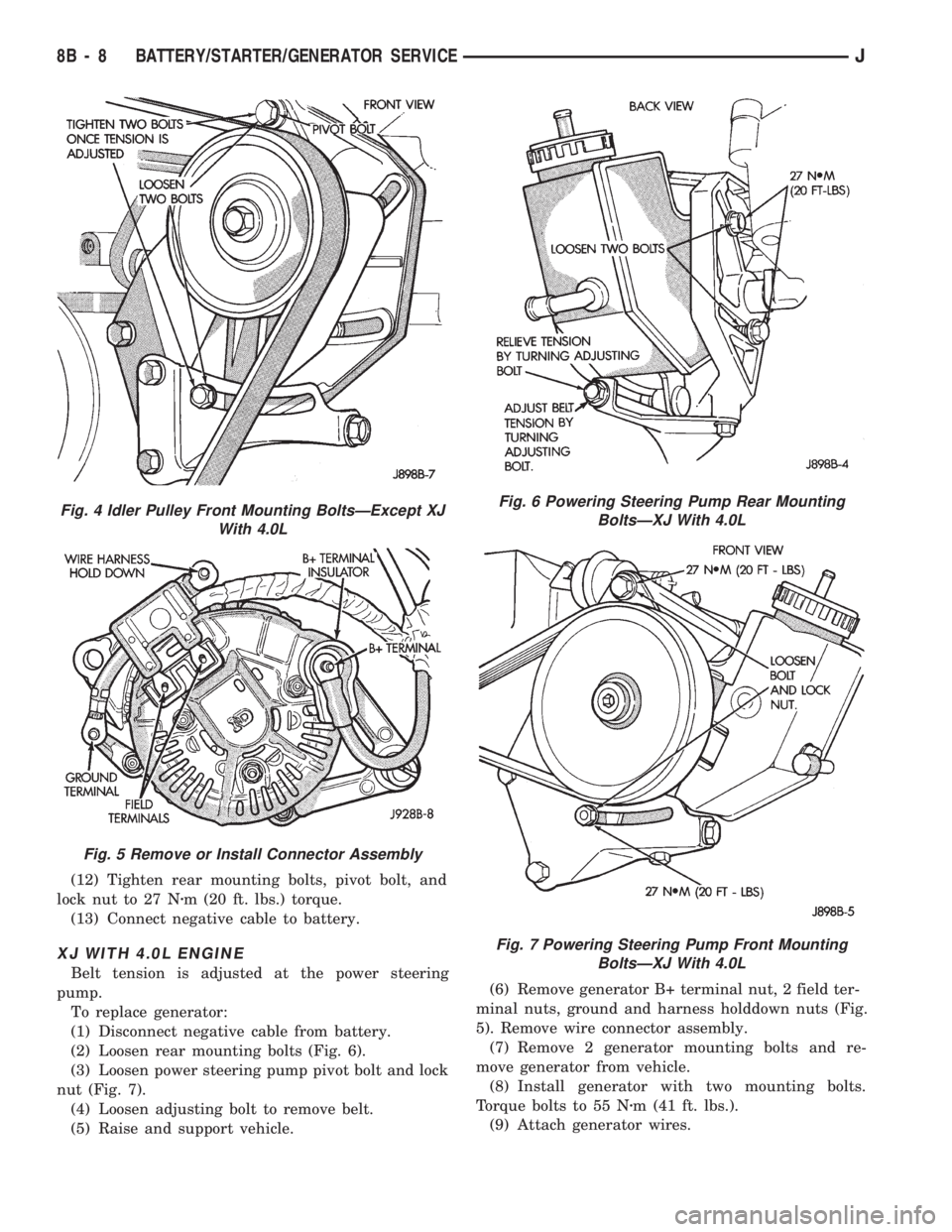
(12) Tighten rear mounting bolts, pivot bolt, and
lock nut to 27 Nzm (20 ft. lbs.) torque.
(13) Connect negative cable to battery.
XJ WITH 4.0L ENGINE
Belt tension is adjusted at the power steering
pump.
To replace generator:
(1) Disconnect negative cable from battery.
(2) Loosen rear mounting bolts (Fig. 6).
(3) Loosen power steering pump pivot bolt and lock
nut (Fig. 7).
(4) Loosen adjusting bolt to remove belt.
(5) Raise and support vehicle.(6) Remove generator B+ terminal nut, 2 field ter-
minal nuts, ground and harness holddown nuts (Fig.
5). Remove wire connector assembly.
(7) Remove 2 generator mounting bolts and re-
move generator from vehicle.
(8) Install generator with two mounting bolts.
Torque bolts to 55 Nzm (41 ft. lbs.).
(9) Attach generator wires.
Fig. 4 Idler Pulley Front Mounting BoltsÐExcept XJ
With 4.0L
Fig. 5 Remove or Install Connector Assembly
Fig. 6 Powering Steering Pump Rear Mounting
BoltsÐXJ With 4.0L
Fig. 7 Powering Steering Pump Front Mounting
BoltsÐXJ With 4.0L
8B - 8 BATTERY/STARTER/GENERATOR SERVICEJ
Page 302 of 1784
CAUTION: Never force a belt over a pulley rim us-
ing a screwdriver as the synthetic fiber may be
damaged.
CAUTION: When installing a serpentine accessory
drive belt, the belt MUST be routed correctly. The
engine may overheat because the water pump will
be rotating in the wrong direction if the belt is in-
stalled incorrectly. Refer to the belt routing label in
engine compartment, or see Group 7 - Belt Sche-
matics.
(10) Place serpentine belt over pulley.
(11) Belt tension adjustment is made at power
steering pump (Fig. 6).
(12) Turn adjusting bolt until belt has correct ten-
sion. See Belt Tension in Specifications.
(13) Tighten rear mounting bolts, pivot bolt, and
lock nut to 27 Nzm (20 ft. lbs.) torque.
(14) Remove support and lower vehicle.
(15) Connect negative cable to battery.
GENERATOR REPLACEMENTÐRIGHT HAND DRIVE
The generator used on the right hand drive is the
same as used on left hand drive. However, the
mounting and accessory drive belt installation are
different.
WARNING: FAILURE TO DISCONNECT NEGATIVE
CABLE FROM BATTERY BEFORE DISCONNECTING
RED (OUTPUT) WIRE CONNECTOR FROM GENER-
ATOR CAN RESULT IN INJURY.
(1) Remove negative cable from battery.
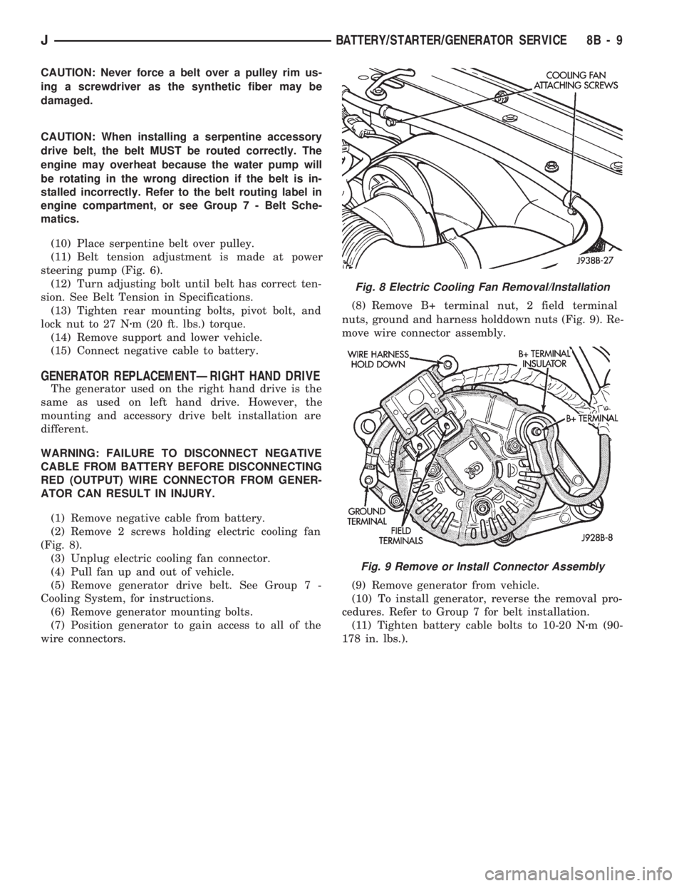
(2) Remove 2 screws holding electric cooling fan
(Fig. 8).
(3) Unplug electric cooling fan connector.
(4) Pull fan up and out of vehicle.
(5) Remove generator drive belt. See Group 7 -
Cooling System, for instructions.
(6) Remove generator mounting bolts.
(7) Position generator to gain access to all of the
wire connectors.(8) Remove B+ terminal nut, 2 field terminal
nuts, ground and harness holddown nuts (Fig. 9). Re-
move wire connector assembly.
(9) Remove generator from vehicle.
(10) To install generator, reverse the removal pro-
cedures. Refer to Group 7 for belt installation.
(11) Tighten battery cable bolts to 10-20 Nzm (90-
178 in. lbs.).
Fig. 8 Electric Cooling Fan Removal/Installation
Fig. 9 Remove or Install Connector Assembly
JBATTERY/STARTER/GENERATOR SERVICE 8B - 9
Page 303 of 1784
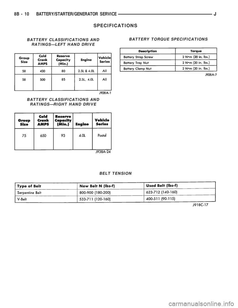
SPECIFICATIONS
BATTERY CLASSIFICATIONS AND
RATINGSÐLEFT HAND DRIVE
BATTERY CLASSIFICATIONS AND
RATINGSÐRIGHT HAND DRIVE
BATTERY TORQUE SPECIFICATIONS
BELT TENSION
8B - 10 BATTERY/STARTER/GENERATOR SERVICEJ
Page 325 of 1784
ENGINE COOLANT TEMPERATURE SENSOR TEST
To perform a complete test of this sensor and its
circuitry, refer to the DRB scan tool. Also refer to the
appropriate Powertrain Diagnostics Procedures man-
ual. To test the sensor only, refer to the following:
The sensor is installed in the thermostat housing
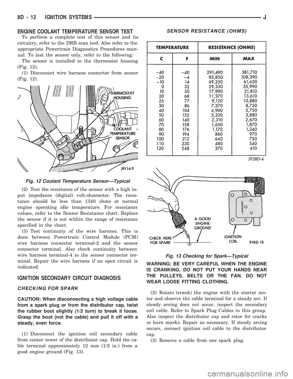
(Fig. 12).
(1) Disconnect wire harness connector from sensor
(Fig. 12).
(2) Test the resistance of the sensor with a high in-
put impedance (digital) volt-ohmmeter. The resis-
tance should be less than 1340 ohms at normal
engine operating idle temperature. For resistance
values, refer to the Sensor Resistance chart. Replace
the sensor if it is not within the range of resistance
specified in the chart.
(3) Test continuity of the wire harness. This is
done between Powertrain Control Module (PCM)
wire harness connector terminal-2 and the sensor
connector terminal. Also check continuity between
wire harness terminal-4 to the sensor connector ter-
minal. Repair the wire harness if an open circuit is
indicated.
IGNITION SECONDARY CIRCUIT DIAGNOSIS
CHECKING FOR SPARK
CAUTION: When disconnecting a high voltage cable
from a spark plug or from the distributor cap, twist
the rubber boot slightly (1/2 turn) to break it loose.
Grasp the boot (not the cable) and pull it off with a
steady, even force.
(1) Disconnect the ignition coil secondary cable
from center tower of the distributor cap. Hold the ca-
ble terminal approximately 12 mm (1/2 in.) from a
good engine ground (Fig. 13).WARNING: BE VERY CAREFUL WHEN THE ENGINE
IS CRANKING. DO NOT PUT YOUR HANDS NEAR
THE PULLEYS, BELTS OR THE FAN. DO NOT
WEAR LOOSE FITTING CLOTHING.
(2) Rotate (crank) the engine with the starter mo-
tor and observe the cable terminal for a steady arc. If
steady arcing does not occur, inspect the secondary
coil cable. Refer to Spark Plug Cables in this group.
Also inspect the distributor cap and rotor for cracks
or burn marks. Repair as necessary. If steady arcing
occurs, connect ignition coil cable to the distributor
cap.
(3) Remove a cable from one spark plug.
Fig. 12 Coolant Temperature SensorÐTypical
SENSOR RESISTANCE (OHMS)
Fig. 13 Checking for SparkÐTypical
8D - 12 IGNITION SYSTEMSJ
Page 350 of 1784
INSTRUMENT CLUSTER DIAGNOSIS
INDEX
page page
4WD Indicator Inoperative................... 4
Anti-Lock Indicator......................... 4
Brake Indicator Inoperative.................. 4
Coolant Temperature Gauge Inoperative........ 3
Coolant Temperature Indicator Inoperative....... 3
Fuel Gauge Inoperative..................... 3
Gauges and Indicators Inoperative............ 3
Instrument Panel Lamps.................... 4
Low Fuel Warning Inoperative................ 4
Low Washer Indicator Inoperative............. 4Malfunction Indicator Lamp (Check Engine)...... 4
Oil Pressure Gauge Inoperative............... 3
Oil Pressure Indicator Inoperative............. 3
Radio/Clock Illumination.................... 4
Seat Belt Indicator........................ 4
Speedomete/Odometer Inoperative............. 3
Tachometer Inoperative..................... 3
Upshift Indicator Inoperative................. 4
Voltmeter Inoperative....................... 3
SPEEDOMETER/ODOMETER INOPERATIVE
(1) Check for continuity in the wire between the
vehicle speed sensor and cluster connector pin A5.
(2) With the ignition switch in the ON position,
check for battery voltage across pin A8 (B+) and pin
B2 (ground).
(3) Perform vehicle speed sensor test. Refer to the
appropriate vehicle Diagnostic Test Procedures man-
ual.
(4) If all the previous tests prove good, replace
speedometer/odometer.
GAUGES AND INDICATORS INOPERATIVE
(1) Remove and inspect fuse #17. Replace as re-
quired.
(2) Measure resistance at instrument cluster con-
nector terminal A3. Meter should read zero ohms. If
not, repair open to ground.
VOLTMETER INOPERATIVE
(1) Turn ignition switch to ON. Voltmeter should
read battery voltage. If not, go to step 2.
(2) Measure voltage at instrument cluster connec-
tor terminal A8. Meter should read battery voltage.
If OK, replace meter. If not, repair open to fuse #17.
OIL PRESSURE GAUGE INOPERATIVE
(1) Turn ignition switch to ON.
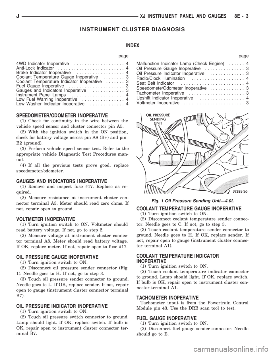
(2) Disconnect oil pressure sender connector (Fig.
1). Needle goes to H. If not, go to step 3.
(3) Touch oil pressure sender connector to ground.
Needle goes to L. If OK, replace sender. If not, repair
open to gauge (instrument cluster connector terminal
B7).
OIL PRESSURE INDICATOR INOPERATIVE
(1) Turn ignition switch to ON.
(2) Touch oil pressure switch connector to ground.
Lamp should light. If OK, replace switch. If bulb is
OK, repair open to instrument cluster connector ter-
minal B7.
COOLANT TEMPERATURE GAUGE INOPERATIVE
(1) Turn ignition switch to ON.
(2) Disconnect coolant temperature sender connec-
tor. Needle goes to C. If not, go to step 3.
(3) Touch coolant temperature sender connector to
ground. Needle goes to H. If OK, replace sender. If
not, repair open to gauge (instrument cluster connec-
tor terminal A1).
COOLANT TEMPERATURE INDICATOR
INOPERATIVE
(1) Turn ignition switch to ON.
(2) Touch coolant temperature indicator connector
to ground. Lamp should light. If OK, replace switch.
If bulb is OK, repair open to instrument cluster con-
nector terminal A1.
TACHOMETER INOPERATIVE
Tachometer input is from the Powertrain Control
Module pin 43. Use the DRB scan tool to test.
FUEL GAUGE INOPERATIVE
(1) Turn ignition switch to ON.
(2) Disconnect fuel gauge sender connector. Needle
should go to E.
Fig. 1 Oil Pressure Sending UnitÐ4.0L
JXJ INSTRUMENT PANEL AND GAUGES 8E - 3
Page 351 of 1784

(3) Connect a jumper between terminal A and B on
the body half of the fuel gauge sender connector. The
gauge should move to F. If gauge is OK, replace
sender. If not, go to step 4.
(4) Measure resistance of sender. Meter should
read 105 to 5 ohms. If OK, go to step 5. If not, re-
place sender.
(5) Check for an open between sender connector
and gauge. If OK, replace gauge. If not, repair open
to gauge.
LOW FUEL WARNING INOPERATIVE
(1) Turn ignition switch to ON.
(2) Disconnect terminal B1 of the instrument clus-
ter connector. Wait at least 10 seconds. Lamp (LED)
should light. If OK, replace sender. If not, replace
low fuel warning module.
UPSHIFT INDICATOR INOPERATIVE
(1) Turn ignition switch to ON.
(2) Ground pin 7 of connector B. Lamp should
light. If not, replace bulb. If OK, continue with
step 3.
(3) Turn ignition switch to OFF. Check for conti-
nuity between connector B pin 2 and pin 54 of the
Powertrain Control Module. If OK, replace PCM. If
not, repair open.
BRAKE INDICATOR INOPERATIVE
(1) Turn ignition switch to ON. Apply parking
brake, brake warning switch connector unplugged.
(2) Jumper brake warning switch connector termi-
nal B to ground. Lamp should light. If bulb is OK,
repair open to indicator.
(3) Turn ignition switch to OFF. Measure resis-
tance between brake warning switch connector ter-
minal A and ground. Meter should read zero ohms. If
OK, check switch and/or brake system. If not, repair
open to park brake switch ground.
4WD INDICATOR INOPERATIVE
(1) Apply parking brake, start engine, vehicle in
4WD Lock or 4WD.
(2) Unplug switch and touch harness side of wire
to ground. Lamp should light. If OK, check switch
operation, replace if bad. If bulb is OK, repair open
to indicator.
LOW WASHER INDICATOR INOPERATIVE
(1) Turn ignition switch to ON.
(2) Jumper 12 volts to fluid level switch connector
terminal B. Lamp should light. If not, go to step 3.
(3) Measure resistance between terminal B and
ground. Meter should read zero ohms. If not, repair
open to bulb. If OK, go to step 4.
(4) Measure voltage at fluid level switch connector
terminal A. Meter should read battery voltage. If
OK, replace switch. If not, repair open to fuse.
MALFUNCTION INDICATOR LAMP (CHECK ENGINE)
(1) Turn ignition switch to ON.
(2) Jumper Powertrain Control Module terminal 2
to ground. Lamp should light. If bulb is OK, check
for open to instrument cluster connector terminal 2.
ANTI-LOCK INDICATOR
(1) Turn ignition switch to ON.
(2) Jumper instrument cluster connector terminal
6 to ground. Lamp should light. If bulb is OK, check
wiring for an open to module. Refer to Group 5 -
Brakes.
SEAT BELT INDICATOR
Jumper instrument cluster connector terminal 15
to 12 volts. Lamp should light. If not, replace bulb. If
OK, check wiring for an open to buzzer module. Re-
fer to Group 8U - Chime/Buzzer Warning Systems.
RADIO/CLOCK ILLUMINATION
With the ignition switch in ACCESSORY or ON,
power comes from the radio fuse. It then goes
through the normally closed contacts of the radio il-
lumination relay to the radio at connector terminal
11.
Pulling the headlamp switch to ON energizes the
radio illumination relay. This closes the normally
open contacts of the relay, and the brightness for the
radio display is controlled by the headlamp switch
rheostat. The back-lighting for the radio is also con-
trolled by the headlamp rheostat through radio con-
nector terminal 10.
Refer to Group 8F - Audio Systems, for radio illu-
mination relay diagnosis.
INSTRUMENT PANEL LAMPS
Voltage is supplied at all times from the 40 amp
Maxi fuse (located in the Power Distribution Center)
through the park lamps fuse to the headlamp switch.
The circuit continues through the instrument lamps
fuse to the individual instrument panel lamps to
ground. Lamp brightness is controlled by turning the
headlamp switch knob.
DIAGNOSIS
(1) Turn parking lamps ON.
(2) Check park lamps fuse. Replace as required.
(3) Check instrument lamps fuse. Replace as re-
quired.
(4) Measure voltage at battery side of instrument
lamps fuse with rheostat turned counterclockwise to
clockwise (LO to HI). Meter should read zero volts to
battery voltage. If not, replace headlamp switch.
(5) Measure resistance at ground side of instru-
ment lamps fuse with parking lamps OFF. Meter
should read almost zero ohms (except bulb filament).
If not, repair open to ground. If zero ohms, 12 volt
supply wire from fuse is shorted to ground, repair short.
8E - 4 XJ INSTRUMENT PANEL AND GAUGESJ
Page 361 of 1784

INSTRUMENT PANEL AND GAUGESÐYJE
CONTENTS
page page
GAUGE PACKAGE DIAGNOSIS............ 22
GAUGE PACKAGE GENERAL INFORMATION . 22
GAUGE PACKAGE SERVICE PROCEDURES . . 24
INSTRUMENT CLUSTER DIAGNOSIS....... 14INSTRUMENT CLUSTER GENERAL INFORMATION.14
INSTRUMENT CLUSTER SERVICE PROCEDURES.. 17
SPECIFICATIONS....................... 27
INSTRUMENT CLUSTER GENERAL INFORMATION
SPEEDOMETER/ODOMETER SYSTEM
The speedometer/odometer system consists of an
electric speedometer and pushbutton reset odometer
mounted in the cluster. The system also includes the
wire harness from the cluster to the vehicle speed
sensor at the transmission, and the adapter and pin-
ion in the transmission. A signal is sent from a
transmission mounted vehicle speed sensor to the
speedometer/odometer circuitry through the wiring
harness. Refer to Group 21 - Transmission for select-
ing the proper pinion, and selecting and indexing the
proper adapter.
TACHOMETER
The tachometer displays the engine speed (RPM).
With the engine running, the tachometer receives anengine speed signal from the Powertrain Control
Module pin 43 (values shown in Specifications chart).
INDICATOR LAMPS
The Brake, Upshift (2.5L with 5 speed transmis-
sion except California), and Malfunction Indicator
(Check Engine) lamps are located in the indicator
lamp panel above the steering column. The lamps
share a common battery feed connection through the
ignition switch and fuse #9.
The turn signals, high beam indicator, seat belt re-
minder, hazard lamp, master lighting and illumina-
tion bulbs are supplied battery voltage through
various switches and share a common ground.
INSTRUMENT CLUSTER DIAGNOSIS
INDEX
page page
Brake Indicator Lamp...................... 16
DiagnosingÐAll Lamps Out................. 16
Instrument Panel Illumination Lamps.......... 16
Malfunction Indicator Lamp (Check Engine)..... 16Seat Belt Reminder Lamp................... 16
Speedometer............................ 14
Tachometer............................. 14
Upshift Indicator Lamp..................... 16
SPEEDOMETER
(1) Raise vehicle.
(2) Disconnect the vehicle speed sensor connector.
(3) Connect a voltmeter between the black wire
pin of the connector and ground.
(4) Turn the ignition switch to the ON position.
(5) Check for approximately 5 volts. If OK, per-
form vehicle speed sensor test. Refer to the appropri-
ate Powertrain Diagnostic Procedures manual. If not
OK, continue with step 6.
(6) Turn ignition switch to OFF position.(7) Check continuity between vehicle speed sensor
connector and terminal 13 of instrument cluster con-
nector. If OK, replace speedometer. If not OK, repair
open circuit.
TACHOMETER
(1) Tachometer input is from the Powertrain Con-
trol Module (PCM) pin 43. Use the DRB scan tool to
perform actuator test. If OK, continue with step 2. If
not, replace PCM.
(2) Check for continuity between cluster connector
pin 12 and PCM pin 43. If OK, replace tachometer. If
not, repair open circuit.
8E - 14 YJ INSTRUMENT PANEL AND GAUGESJ
Page 363 of 1784

DIAGNOSINGÐALL LAMPS OUT
(1) Inspect fuse #9. Replace as required.
(2) Measure voltage at instrument cluster connec-
tor terminal 20. Meter should read zero ohms. If not,
repair open to ground.
UPSHIFT INDICATOR LAMP
Vehicles equipped with manual transmissions have
an optional upshift indicator lamp. The lamp is con-
trolled by the PCM. The lamp lights to indicate when
the driver should shift to the next highest gear for best
fuel economy. The PCM will turn the lamp off after 3 to
5 seconds if the upshift is not performed. The lamp will
remain off until the vehicle stops accelerating and is
brought back to the range of lamp operation or shifted
into another gear.
The indicator lamp is normally illuminated when
the ignition switch is turned ON and it is turned off
when the engine is started. The lamp will be lighted
during engine operation according to engine speed
and load.
(1) Turn ignition switch to ON.
(2) Ground pin 2 of cluster connector. Lamp should
light. If not, replace bulb. If OK, continue with step 3.
(3) Turn ignition switch to OFF. Check for conti-
nuity between cluster connector pin 2 and pin 54 of
the PCM. If not, repair open. If OK, refer to DRB
scan tool actuator test of upshift indicator.
BRAKE INDICATOR LAMP
The brake indicator is a dual function lamp. It will in-
dicate an unequal pressure condition in the split brake
hydraulic system and it also will indicate when the park-
ing brake is engaged. Separate switches are used for each
indicator lamp function. A switch mounted on the brake
pedal assembly will close a ground circuit whenever the
parking brakes are applied. A second switch is installed
in the brake hydraulic lines near the master cylinder. If
the switch is balanced by equal pressure on both ends of
the switch valve, the valve remains centered and the
lamp remains off. If the valve is shifted by unequal pres-
sure between the front or rear brake hydraulic systems,
the lamp circuit is connected to ground. To make sure
the brake lamp is functional before the vehicle is driven,
it is illuminated through a ground circuit when the igni-
tion switch is turned to the START position.
(1) Turn ignition switch to ON.
(2) Ground pin 1 of the cluster connector. Lamp
should light. If not, replace bulb. If OK, continue
with step 3.
(3) Turn ignition switch to OFF. Check for continuity to
park brake switch and brake warning switch.
MALFUNCTION INDICATOR LAMP (CHECK ENGINE)
The Malfunction Indicator Lamp (Check Engine) il-
luminates each time the ignition switch is turned
ON and stays on for 3 seconds as a bulb test.If the PCM receives an incorrect signal or no signal
from certain sensors or emission related systems the
lamp is turned on (pin 32 of PCM). This is a warning
that the PCM has recorded a system or sensor mal-
function. In some cases when a diagnostic fault is de-
clared the PCM will go into a limp-in mode in an
attempt to keep the system operating. It signals an
immediate need for service.
The lamp also can be used to display diagnostic
trouble codes (DTC). Cycle the ignition switch ON,
OFF, ON, OFF, ON within 5 seconds. This will allow
any DTC's stored in the PCM memory to be dis-
played in a series of flashes representing digits.
(1) Turn ignition switch to ON.
(2) Ground pin 4 of cluster connector. Lamp should
light. If not, replace bulb. If OK, continue with step 3.
(3) Turn ignition switch to OFF. Check for conti-
nuity between cluster connector pin 4 and PCM cav-
ity 32. If OK, replace PCM. If not, repair open.
SEAT BELT REMINDER LAMP
Apply 12 volts to terminal 16 of cluster connector.
Lamp should light. If not, replace bulb. If OK, check
wiring for an open to buzzer module. Refer to Group
8U - Chime/Buzzer Warning Systems.
INSTRUMENT PANEL ILLUMINATION LAMPS
The instrument panel illumination lamps share
two common connections. There is a splice after fuse
#10 that connects the lamps to battery feed. There is
also a splice that connects all lamps to ground. Be-
cause they share these common connection points in
a parallel circuit, the illumination lamps will all
come on at the same time. It also means one or more
lamps can be out without affecting the operation of
the other lamps.
On the battery side of the circuit, the headlamp
switch illumination rheostat/switch and panel lamps
fuse receive battery feed in series from the park/tail
fuse. In the park lamp position, the headlamp switch
completes the circuit from the park/tail fuse to the il-
lumination rheostat/switch and panel lamps fuse.
The illumination rheostat contains a variable resis-
tor that allows the driver to vary illumination inten-
sity from off to full brightness.
DIAGNOSIS
(1) Turn parking lamps ON.
(2) Check fuse #10. Replace as required.
(3) Measure voltage at battery side of fuse #10
with rheostat turned counterclockwise to clockwise
(LO to HI). Meter should read zero volts to battery
voltage. If not, replace headlamp switch.
(4) Measure resistance at ground side of fuse #10
with parking lamps OFF. Meter should read almost
zero ohms (except bulb filament). If not, repair open
to ground. If zero ohms, 12 volt supply wire from fuse
is shorted to ground, repair short.
8E - 16 YJ INSTRUMENT PANEL AND GAUGESJ