1994 JEEP CHEROKEE instrument panel
[x] Cancel search: instrument panelPage 1685 of 1784
CLIMATE CONTROL SYSTEMÐXJ VEHICLES
INDEX
page page
A/C Recirculating Air Door Vacuum Motor
Replacement.......................... 31
Blower Motor Resistors Replacement......... 35
Blower Motor/Fan Replacement.............. 26
CondenserÐ4.0L Engines.................. 32
Condenser/Receiver DrierÐ2.5L Engines....... 31
Defroster Duct Replacement................ 29
Description............................. 22
Evaporator Coil.......................... 34
Evaporator/Blower Housing................. 33Expansion (H) Valve...................... 35
Heater and A/C Control Panel Replacement.... 26
Heater Control Cable Replacement........... 30
Heater Core............................ 28
Heater Core Housing Replacement........... 29
Heater/Defroster/Instrument Panel Outlet Door
Vacuum Motor Replacement............... 30
Receiver DrierÐ4.0L Engines............... 32
Temperature Control Thermostat............. 35
DESCRIPTION
The Climate Control System combines air condi-
tioning, heating and ventilating capabilities for vehi-
cles equipped with air conditioning. Vehicles without
air conditioning perform heating and ventilating
functions without the air conditioning evaporator.
Both systems consist basically of 2 parts:
²Blower and Air Inlet Assembly
²Heater Core and Air Distribution Assembly
These assemblies, initially installed as a single
unit, may be removed separately from under the in-
strument panel as required for service.
HEATER SYSTEM
The heater system is a blend air type. Outside air
is heated and then blended in varying amounts with
cooler outside air to obtain the desired discharge
temperature. A heater coolant valve provides full
flow to the heater core for all heating modes. The
heater coolant valve remains closed for the ventila-
tion mode, allowing discharge air to approach the
outside ambient air temperature.
AIR CONDITIONING SYSTEM
The air conditioning system has an evaporator to
cool and dehumidify the incoming outside air prior to
blending with the heated air. The evaporator is in
operation during the A/C mode and also in the de-
frost mode for defogging purposes. The evaporator is
not in operation at ambient temperatures below ap-
proximately -1ÉC (30ÉF). To maintain minimum evap-
orator temperature, a fixed thermostat setting switch
cycles the compressor clutch. The blower is operatingthe heater or air conditioning systems, except the
OFF mode. In this mode (OFF) the blower and the
outside air are shut off.
The cooling unit is mounted on the dash panel and
the cooled air is discharged from the instrument
panel registers. The registers are adjusted to provide
general or localized cooling.
SIGHT GLASS
The sight glass is located on top of the receiver/
drier. The sight glass provides a visual check of the
system refrigerant level. A continuous stream of bub-
bles will appear in the sight glass when the system
charge is low. Bubbles will not appear when the sys-
tem is fully charged.
LOW PRESSURE SWITCH
The low pressure switch disengages the magnetic
clutch if the pressure in the system drops below 193
kPa (28 psi). This will occur with a loss in refriger-
ant or with cold ambient temperature.
HEATER VALVE
The heater valve regulates coolant flow to the
heater core. It requires vacuum to shut off flow to
the heater core.
These vehicles are equipped with a bypass-type
heater water valve. When the heater valve is closed,
coolant flow to the heater core is bypassed back to
the engine. When the heater valve is open, coolant is
directed through the heater core and back to the en-
gine.
24 - 22 HEATING AND AIR CONDITIONINGJ
Page 1689 of 1784
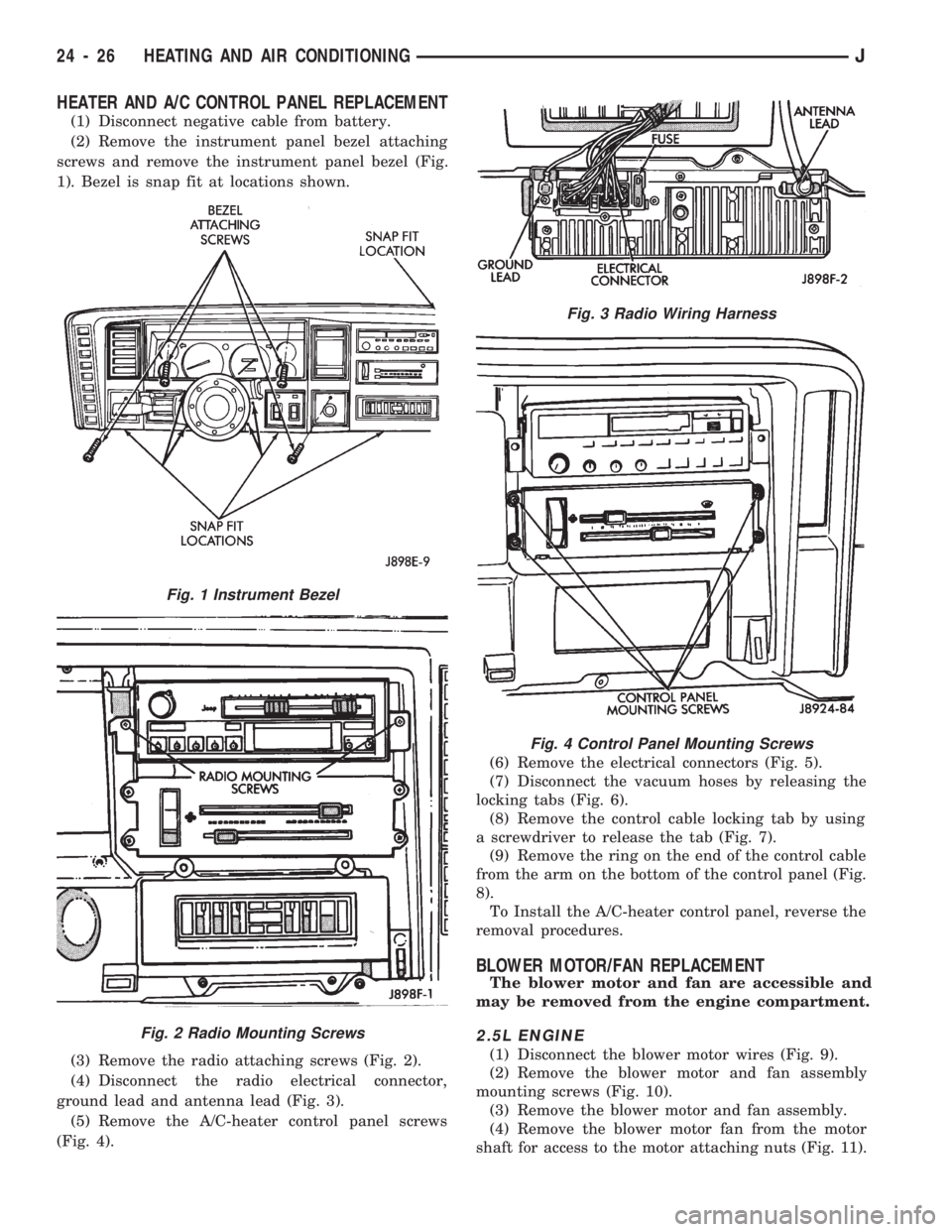
HEATER AND A/C CONTROL PANEL REPLACEMENT
(1) Disconnect negative cable from battery.
(2) Remove the instrument panel bezel attaching
screws and remove the instrument panel bezel (Fig.
1). Bezel is snap fit at locations shown.
(3) Remove the radio attaching screws (Fig. 2).
(4) Disconnect the radio electrical connector,
ground lead and antenna lead (Fig. 3).
(5) Remove the A/C-heater control panel screws
(Fig. 4).(6) Remove the electrical connectors (Fig. 5).
(7) Disconnect the vacuum hoses by releasing the
locking tabs (Fig. 6).
(8) Remove the control cable locking tab by using
a screwdriver to release the tab (Fig. 7).
(9) Remove the ring on the end of the control cable
from the arm on the bottom of the control panel (Fig.
8).
To Install the A/C-heater control panel, reverse the
removal procedures.
BLOWER MOTOR/FAN REPLACEMENT
The blower motor and fan are accessible and
may be removed from the engine compartment.
2.5L ENGINE
(1) Disconnect the blower motor wires (Fig. 9).
(2) Remove the blower motor and fan assembly
mounting screws (Fig. 10).
(3) Remove the blower motor and fan assembly.
(4) Remove the blower motor fan from the motor
shaft for access to the motor attaching nuts (Fig. 11).
Fig. 1 Instrument Bezel
Fig. 2 Radio Mounting Screws
Fig. 3 Radio Wiring Harness
Fig. 4 Control Panel Mounting Screws
24 - 26 HEATING AND AIR CONDITIONINGJ
Page 1692 of 1784
(4) Connect the heater hoses to the heater core.
(5) Fill the cooling system.
HEATER CORE HOUSING REPLACEMENT
(1) Remove the evaporator/blower housing.
(2) Remove the heater core.
(3) Remove the defroster duct.
(4) Disconnect the vacuum hoses from the heater
core housing vacuum motors.
(5) Remove the heater housing retaining nuts in
the engine compartment. Remove the heater core
housing.
(6) Transfer the vacuum motors, etc. to the re-
placement housing.
To install the heater core housing, reverse the re-
moval procedure.
DEFROSTER DUCT REPLACEMENT
REMOVAL
(1) Disconnect negative cable from battery.
(2) If equipped with center console remove the con-
sole as follows:
(a) MANUAL TRANSMISSIONÐRemove shift
knob, boot and bezel.
(b) AUTOMATIC TRANSMISSIONÐRemove
shift handle by pulling up. Remove the shift bezel.
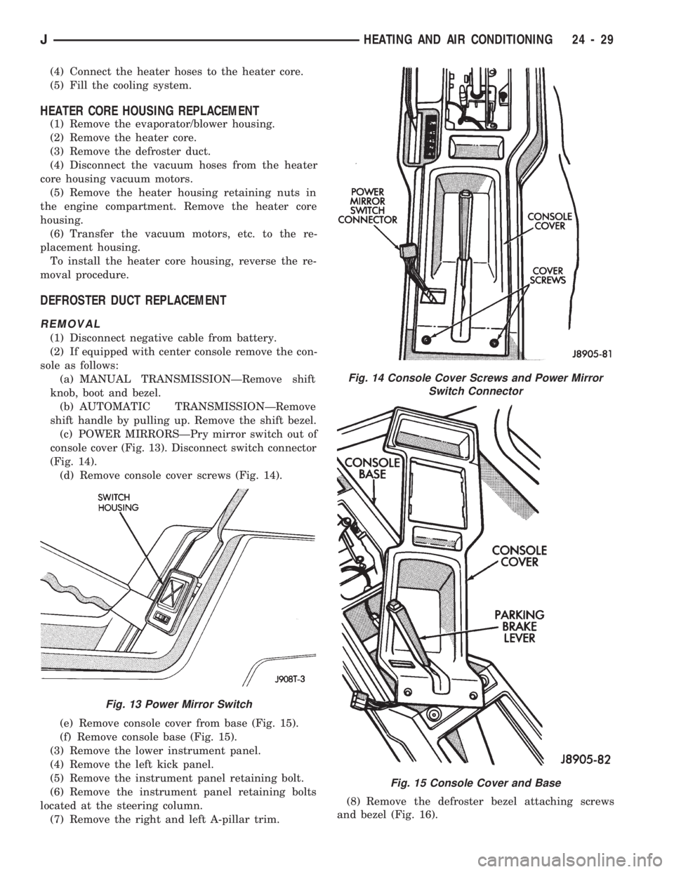
(c) POWER MIRRORSÐPry mirror switch out of
console cover (Fig. 13). Disconnect switch connector
(Fig. 14).
(d) Remove console cover screws (Fig. 14).
(e) Remove console cover from base (Fig. 15).
(f) Remove console base (Fig. 15).
(3) Remove the lower instrument panel.
(4) Remove the left kick panel.
(5) Remove the instrument panel retaining bolt.
(6) Remove the instrument panel retaining bolts
located at the steering column.
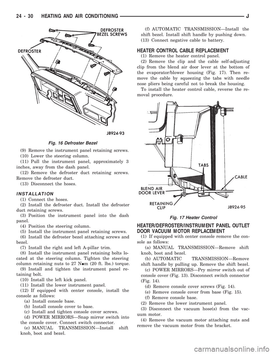
(7) Remove the right and left A-pillar trim.(8) Remove the defroster bezel attaching screws
and bezel (Fig. 16).
Fig. 13 Power Mirror Switch
Fig. 14 Console Cover Screws and Power Mirror
Switch Connector
Fig. 15 Console Cover and Base
JHEATING AND AIR CONDITIONING 24 - 29
Page 1693 of 1784
(9) Remove the instrument panel retaining screws.
(10) Lower the steering column.
(11) Pull the instrument panel, approximately 3
inches, away from the dash panel.
(12) Remove the defroster duct retaining screws.
Remove the defroster duct.
(13) Disconnect the hoses.
INSTALLATION
(1) Connect the hoses.
(2) Install the defroster duct. Install the defroster
duct retaining screws.
(3) Position the instrument panel into the dash
panel.
(4) Position the steering column.
(5) Install the instrument panel retaining screws.
(6) Install the defroster bezel attaching screws and
bezel.
(7) Install the right and left A-pillar trim.
(8) Install the instrument panel retaining bolts lo-
cated at the steering column. Tighten the steering
column retaining nuts to 27 NIm (20 ft. lbs.) torque.
(9) Install and tighten the instrument panel re-
taining bolt.
(10) Install the left kick panel.
(11) Install the lower instrument panel.
(12) If equipped with center console, install the
console as follows:
(a) Install console base.
(b) Install console cover to base.
(c) Install and tighten console cover screws.
(d) POWER MIRRORSÐSnap mirror switch into
the console cover. Connect switch connector.
(e) MANUAL TRANSMISSIONÐInstall shift
knob, boot and bezel.(f) AUTOMATIC TRANSMISSIONÐInstall the
shift bezel. Install shift handle by pushing down.
(13) Connect negative cable to battery.
HEATER CONTROL CABLE REPLACEMENT
(1) Remove the heater control panel.
(2) Remove the clip and the cable self-adjusting
clip from the blend air door lever at the bottom of
the evaporator/blower housing (Fig. 17). Then re-
move the cable by squeezing the tabs with needle
nose pliers being careful not to break the housing.
To install the heater control cable, reverse the re-
moval procedure.
HEATER/DEFROSTER/INSTRUMENT PANEL OUTLET
DOOR VACUUM MOTOR REPLACEMENT
(1) If equipped with center console remove the con-
sole as follows:
(a) MANUAL TRANSMISSIONÐRemove shift
knob, boot and bezel.
(b) AUTOMATIC TRANSMISSIONÐRemove
shift handle by pulling up. Remove the shift bezel.
(c) POWER MIRRORSÐPry mirror switch out of
console cover (Fig. 13). Disconnect switch connector
(Fig. 14).
(d) Remove console cover screws (Fig. 14).
(e) Remove console cover from base (Fig. 15).
(f) Remove console base.
(2) Remove the lower instrument panel.
(3) Disconnect the vacuum hose(s) from the vac-
uum motor.
(4) Remove the vacuum motor attaching nuts and
remove the vacuum motor from the bracket.
Fig. 16 Defroster Bezel
Fig. 17 Heater Control
24 - 30 HEATING AND AIR CONDITIONINGJ
Page 1696 of 1784
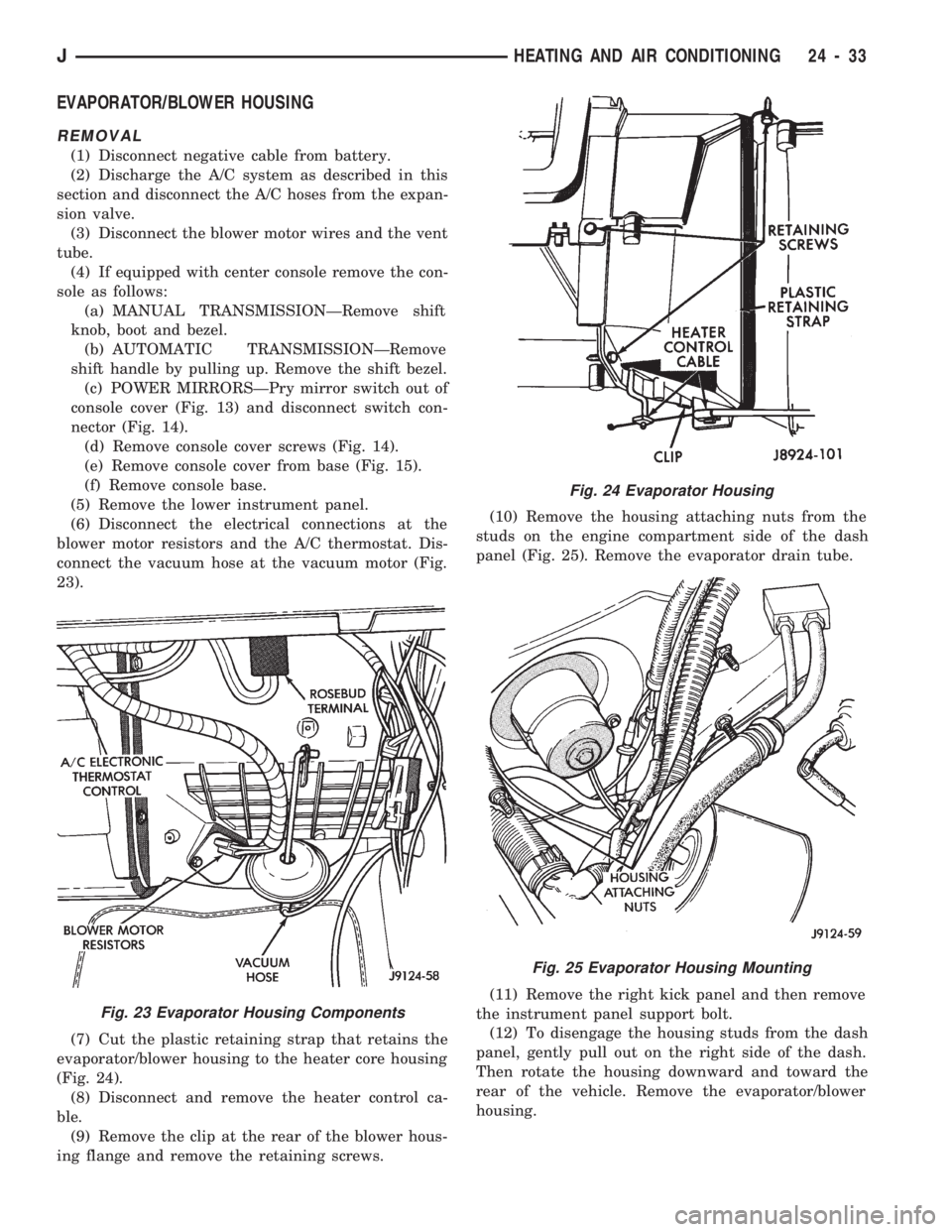
EVAPORATOR/BLOWER HOUSING
REMOVAL
(1) Disconnect negative cable from battery.
(2) Discharge the A/C system as described in this
section and disconnect the A/C hoses from the expan-
sion valve.
(3) Disconnect the blower motor wires and the vent
tube.
(4) If equipped with center console remove the con-
sole as follows:
(a) MANUAL TRANSMISSIONÐRemove shift
knob, boot and bezel.
(b) AUTOMATIC TRANSMISSIONÐRemove
shift handle by pulling up. Remove the shift bezel.
(c) POWER MIRRORSÐPry mirror switch out of
console cover (Fig. 13) and disconnect switch con-
nector (Fig. 14).
(d) Remove console cover screws (Fig. 14).
(e) Remove console cover from base (Fig. 15).
(f) Remove console base.
(5) Remove the lower instrument panel.
(6) Disconnect the electrical connections at the
blower motor resistors and the A/C thermostat. Dis-
connect the vacuum hose at the vacuum motor (Fig.
23).
(7) Cut the plastic retaining strap that retains the
evaporator/blower housing to the heater core housing
(Fig. 24).
(8) Disconnect and remove the heater control ca-
ble.
(9) Remove the clip at the rear of the blower hous-
ing flange and remove the retaining screws.(10) Remove the housing attaching nuts from the
studs on the engine compartment side of the dash
panel (Fig. 25). Remove the evaporator drain tube.
(11) Remove the right kick panel and then remove
the instrument panel support bolt.
(12) To disengage the housing studs from the dash
panel, gently pull out on the right side of the dash.
Then rotate the housing downward and toward the
rear of the vehicle. Remove the evaporator/blower
housing.
Fig. 23 Evaporator Housing Components
Fig. 24 Evaporator Housing
Fig. 25 Evaporator Housing Mounting
JHEATING AND AIR CONDITIONING 24 - 33
Page 1697 of 1784
INSTALLATION
(1) Position the evaporator/blower housing into
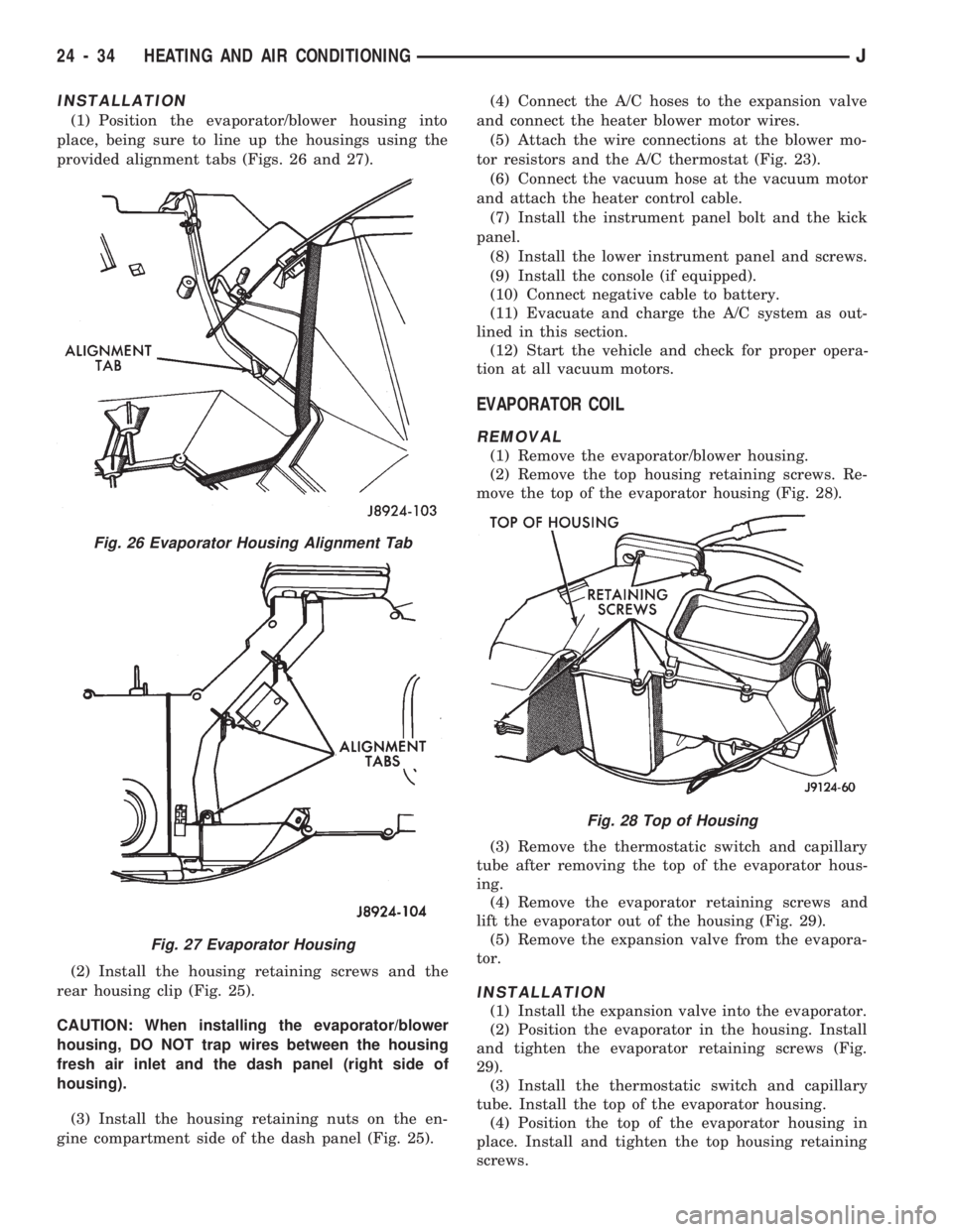
place, being sure to line up the housings using the
provided alignment tabs (Figs. 26 and 27).
(2) Install the housing retaining screws and the
rear housing clip (Fig. 25).
CAUTION: When installing the evaporator/blower
housing, DO NOT trap wires between the housing
fresh air inlet and the dash panel (right side of
housing).
(3) Install the housing retaining nuts on the en-
gine compartment side of the dash panel (Fig. 25).(4) Connect the A/C hoses to the expansion valve
and connect the heater blower motor wires.
(5) Attach the wire connections at the blower mo-
tor resistors and the A/C thermostat (Fig. 23).
(6) Connect the vacuum hose at the vacuum motor
and attach the heater control cable.
(7) Install the instrument panel bolt and the kick
panel.
(8) Install the lower instrument panel and screws.
(9) Install the console (if equipped).
(10) Connect negative cable to battery.
(11) Evacuate and charge the A/C system as out-
lined in this section.
(12) Start the vehicle and check for proper opera-
tion at all vacuum motors.
EVAPORATOR COIL
REMOVAL
(1) Remove the evaporator/blower housing.
(2) Remove the top housing retaining screws. Re-
move the top of the evaporator housing (Fig. 28).
(3) Remove the thermostatic switch and capillary
tube after removing the top of the evaporator hous-
ing.
(4) Remove the evaporator retaining screws and
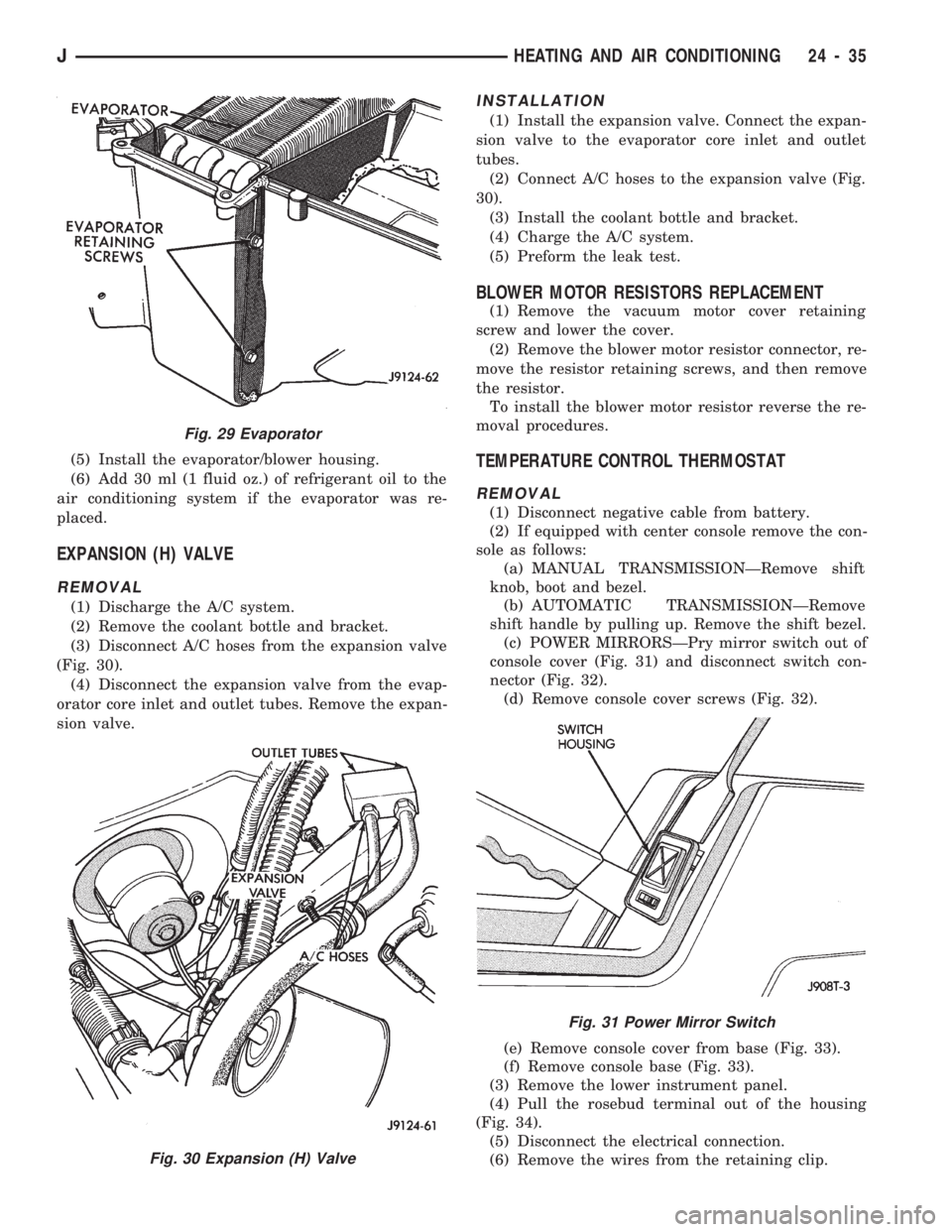
lift the evaporator out of the housing (Fig. 29).
(5) Remove the expansion valve from the evapora-
tor.
INSTALLATION
(1) Install the expansion valve into the evaporator.
(2) Position the evaporator in the housing. Install
and tighten the evaporator retaining screws (Fig.
29).
(3) Install the thermostatic switch and capillary
tube. Install the top of the evaporator housing.
(4) Position the top of the evaporator housing in
place. Install and tighten the top housing retaining
screws.
Fig. 26 Evaporator Housing Alignment Tab
Fig. 27 Evaporator Housing
Fig. 28 Top of Housing
24 - 34 HEATING AND AIR CONDITIONINGJ
Page 1698 of 1784
(5) Install the evaporator/blower housing.
(6) Add 30 ml (1 fluid oz.) of refrigerant oil to the
air conditioning system if the evaporator was re-
placed.
EXPANSION (H) VALVE
REMOVAL
(1) Discharge the A/C system.
(2) Remove the coolant bottle and bracket.
(3) Disconnect A/C hoses from the expansion valve
(Fig. 30).
(4) Disconnect the expansion valve from the evap-
orator core inlet and outlet tubes. Remove the expan-
sion valve.
INSTALLATION
(1) Install the expansion valve. Connect the expan-
sion valve to the evaporator core inlet and outlet
tubes.
(2) Connect A/C hoses to the expansion valve (Fig.
30).
(3) Install the coolant bottle and bracket.
(4) Charge the A/C system.
(5) Preform the leak test.
BLOWER MOTOR RESISTORS REPLACEMENT
(1) Remove the vacuum motor cover retaining
screw and lower the cover.
(2) Remove the blower motor resistor connector, re-
move the resistor retaining screws, and then remove
the resistor.
To install the blower motor resistor reverse the re-
moval procedures.
TEMPERATURE CONTROL THERMOSTAT
REMOVAL
(1) Disconnect negative cable from battery.
(2) If equipped with center console remove the con-
sole as follows:
(a) MANUAL TRANSMISSIONÐRemove shift
knob, boot and bezel.
(b) AUTOMATIC TRANSMISSIONÐRemove
shift handle by pulling up. Remove the shift bezel.
(c) POWER MIRRORSÐPry mirror switch out of
console cover (Fig. 31) and disconnect switch con-
nector (Fig. 32).
(d) Remove console cover screws (Fig. 32).
(e) Remove console cover from base (Fig. 33).
(f) Remove console base (Fig. 33).
(3) Remove the lower instrument panel.
(4) Pull the rosebud terminal out of the housing
(Fig. 34).
(5) Disconnect the electrical connection.
(6) Remove the wires from the retaining clip.
Fig. 29 Evaporator
Fig. 30 Expansion (H) Valve
Fig. 31 Power Mirror Switch
JHEATING AND AIR CONDITIONING 24 - 35
Page 1702 of 1784
FRESH AIR VENTILATION
The fresh air ventilating system (Fig. 3) is oper-
ated by the air control lever. When the lever is
moved to VENT position, outside air from the cowl
intake flows into the heater housing. Incoming air is
directed into the vehicle interior through vent doors
in the housing.
A door in the intake duct controls air flow into the
duct. The door is operated by a vacuum motor. The
motor is controlled by a vacuum switch in the heater
control panel. The vent air doors are opened and
closed by a cable and linkage operated by the air
control lever. Fresh air intake occurs only when the
lever is in the VENT position.
HEATER CONTROL PANEL REPLACEMENT
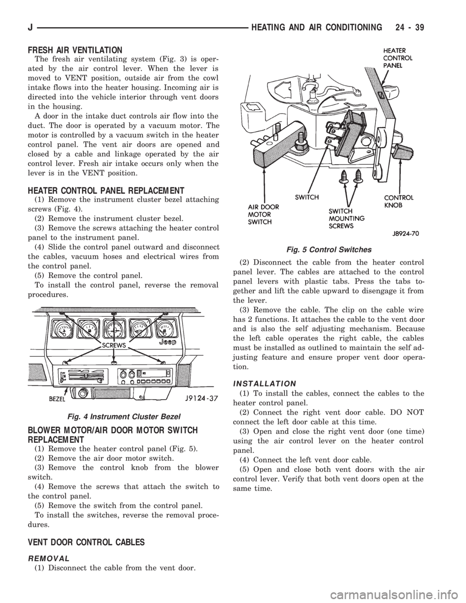
(1) Remove the instrument cluster bezel attaching
screws (Fig. 4).
(2) Remove the instrument cluster bezel.
(3) Remove the screws attaching the heater control
panel to the instrument panel.
(4) Slide the control panel outward and disconnect
the cables, vacuum hoses and electrical wires from
the control panel.
(5) Remove the control panel.
To install the control panel, reverse the removal
procedures.
BLOWER MOTOR/AIR DOOR MOTOR SWITCH
REPLACEMENT
(1) Remove the heater control panel (Fig. 5).
(2) Remove the air door motor switch.
(3) Remove the control knob from the blower
switch.
(4) Remove the screws that attach the switch to
the control panel.
(5) Remove the switch from the control panel.
To install the switches, reverse the removal proce-
dures.
VENT DOOR CONTROL CABLES
REMOVAL
(1) Disconnect the cable from the vent door.(2) Disconnect the cable from the heater control
panel lever. The cables are attached to the control
panel levers with plastic tabs. Press the tabs to-
gether and lift the cable upward to disengage it from
the lever.
(3) Remove the cable. The clip on the cable wire
has 2 functions. It attaches the cable to the vent door
and is also the self adjusting mechanism. Because
the left cable operates the right cable, the cables
must be installed as outlined to maintain the self ad-
justing feature and ensure proper vent door opera-
tion.
INSTALLATION
(1) To install the cables, connect the cables to the
heater control panel.
(2) Connect the right vent door cable. DO NOT
connect the left door cable at this time.
(3) Open and close the right vent door (one time)
using the air control lever on the heater control
panel.
(4) Connect the left vent door cable.
(5) Open and close both vent doors with the air
control lever. Verify that both vent doors open at the
same time.
Fig. 4 Instrument Cluster Bezel
Fig. 5 Control Switches
JHEATING AND AIR CONDITIONING 24 - 39