1994 JEEP CHEROKEE differential
[x] Cancel search: differentialPage 27 of 1784
If the transfer case ATF is warm, it is accept-
able for the fluid to drip out of the fill hole. If
the fluid gushes out of the fill hole, the level is
too high.
(3) If the level is low, raise it to the bottom edge of
the fill hole with MOPAR ATF PLUS type 7176 or
an equivalent MerconŸ/Dexron IIŸ ATF.
(4) Install the fill-hole plug. Tighten the plug with
47 NIm (35 ft. lbs.) torque.
(5) Remove the support and lower the vehicle.
FLUID CHANGE
When it becomes necessary to change the ATF in a
Jeepttransfer case, use the following procedure.
(1) Raise and support the vehicle.
(2) Remove the fill-hole plug from the transfer
case.
(3) Place an appropriate container under the trans-
fer case drain-hole plug.
(4) Remove the drain-hole plug and drain the ATF
from the transfer case into the container.
Care should be exercised when disposing used
ATF after it has been drained from a transfer
case.
CAUTION: Do not over-tighten the drain and fill-hole
plugs. Over-tightening can strip the hole threads
and/or crack the aluminum housing.
(5) Install the drain-hole plug in the transfer case.
Tighten the plug with 47 NIm (35 ft. lbs.) torque.
(6) Fill the transfer case to the bottom edge of the
fill hole with MOPAR ATF PLUS type 7176 (or an
equivalent MerconŸ/Dexron IIŸ ATF).
(7) Install the fill-hole plug in the transfer case.
Tighten the plug with 47 NIm (35 ft. lbs.) torque.
(8) Remove the support and lower the vehicle.
FRONT AND REAR AXLES
RECOMMENDED MAINTENANCE
The lubricant level in axle differential housings
should be determined at the same time as the engine
oil is changed and the oil filter is replaced. Add lu-
bricant as necessary.
In addition, with normal driving conditions, the
axle lubricant should be changed after each 48
000-km (30,000-miles). With severe driving condi-
tions, after each 29 000-km (12,000-miles).
LUBRICANT SPECIFICATIONS
For normal vehicle operation, use SAE 75W-90,
API Quality Grade GL-5 gear lubricant in all Jeept
front (4WD only) and rear axles. Vehicles equipped
with a Trac-Loc rear axle also require a friction mod-
ifier additive with the gear lubricant.
When involved in trailer towing applications
use SAE 80W-140, API Quality Grade GL-5 gearlubricant in the rear axle. XJ Vehicles equipped
with a class III trailer hitch require SAE
75W-140 synthetic gear lubricant in the rear
axle.
LUBRICANT LEVEL
Determine the axle differential housing lubricant
level according to the following procedure.
(1) Raise and support the vehicle.
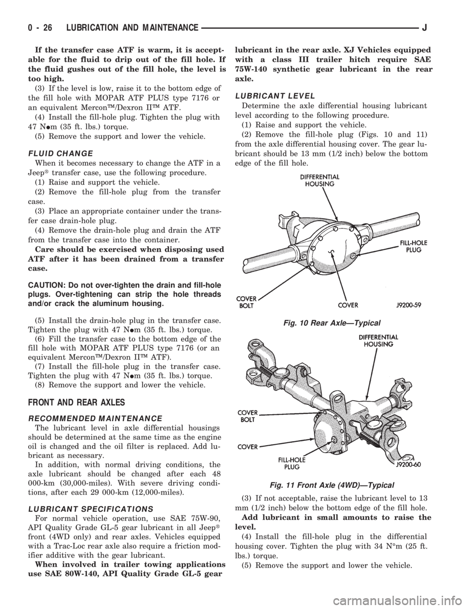
(2) Remove the fill-hole plug (Figs. 10 and 11)
from the axle differential housing cover. The gear lu-
bricant should be 13 mm (1/2 inch) below the bottom
edge of the fill hole.
(3) If not acceptable, raise the lubricant level to 13
mm (1/2 inch) below the bottom edge of the fill hole.
Add lubricant in small amounts to raise the
level.
(4) Install the fill-hole plug in the differential
housing cover. Tighten the plug with 34 NÉm (25 ft.
lbs.) torque.
(5) Remove the support and lower the vehicle.
Fig. 10 Rear AxleÐTypical
Fig. 11 Front Axle (4WD)ÐTypical
0 - 26 LUBRICATION AND MAINTENANCEJ
Page 28 of 1784
LUBRICANT CHANGE
When it becomes necessary to change the axle lu-
bricant in a Jeeptfront or rear axle, use the follow-
ing procedure.
(1) Raise and support the vehicle.
(2) Place a container under the axle differential
housing.
(3) Remove the axle differential housing cover
bolts. Remove the housing cover.
(4) Allow the axle gear lubricant to completely
drain into the container.
CAUTION: Do not flush a rear axle Trac-Loc differ-
ential. Trac-Loc differentials may be cleaned only
by disassembling the unit and wiping the compo-
nents with clean, lint-free cloth.
(5) Flush the inside of the differential housing
with a flushing oil.Do not use water, steam, ker-
osene or gasoline for flushing.
(6) Remove any residual RTV sealant/gasket mate-
rial from the differential housing and cover. Thor-
oughly clean the contact surfaces with mineral
spirits and dry the surfaces completely.
(7) Apply a`bead of MOPAR RTV Sealant, or an
equivalent sealant, around the bolt circle on the
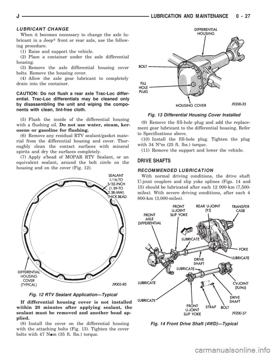
housing and on the cover (Fig. 12).
If differential housing cover is not installed
within 20 minutes after applying sealant, the
sealant must be removed and another bead ap-
plied.
(8) Install the cover on the differential housing
with the attaching bolts (Fig. 13). Tighten the cover
bolts with 47 NIm (35 ft. lbs.) torque.(9) Remove the fill-hole plug and add the replace-
ment gear lubricant to the differential housing. Refer
to Specifications above.
(10) Install the fill-hole plug. Tighten the plug
with 34 NÉm (25 ft. lbs.) torque.
(11) Remove the support and lower the vehicle.
DRIVE SHAFTS
RECOMMENDED LUBRICATION
With normal driving conditions, the drive shaft
U-joint couplers and slip yoke splines (Figs. 14 and
15) should be lubricated after each 12 000-km (7,500-
miles). With severe driving conditions, after each 4
800-km (3,000-miles).
Fig. 12 RTV Sealant ApplicationÐTypical
Fig. 13 Differential Housing Cover Installed
Fig. 14 Front Drive Shaft (4WD)ÐTypical
JLUBRICATION AND MAINTENANCE 0 - 27
Page 32 of 1784
FRONT WHEEL BEARINGS
Only 2WD XJ vehicles are equipped with front
wheel bearings. XJ vehicles have semi-floating axle
shafts and axle shaft bearings that are lubricated via
differential lube oil.
RECOMMENDED MAINTENANCEÐ2WD XJ
VEHICLES
The front wheel bearings should be lubricated (re-
packed) at the same time as front brake pad/caliper
service is conducted.
LUBRICANT SPECIFICATION
Wheel bearings should be lubricated with a lubri-
cant that is identified as NLGI GC-LB lubricant.
INSPECTION/LUBRICATION
(1) Remove the wheel/tire and the disc brake cali-
per.Do not disconnect the caliper brake fluid
hose unless the caliper must also be removed for
maintenance. Support the caliper with a hanger
to prevent brake fluid hose damage.
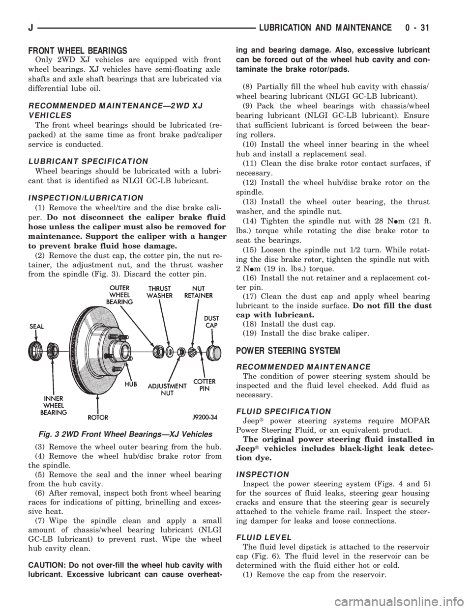
(2) Remove the dust cap, the cotter pin, the nut re-
tainer, the adjustment nut, and the thrust washer
from the spindle (Fig. 3). Discard the cotter pin.
(3) Remove the wheel outer bearing from the hub.
(4) Remove the wheel hub/disc brake rotor from
the spindle.
(5) Remove the seal and the inner wheel bearing
from the hub cavity.
(6) After removal, inspect both front wheel bearing
races for indications of pitting, brinelling and exces-
sive heat.
(7) Wipe the spindle clean and apply a small
amount of chassis/wheel bearing lubricant (NLGI
GC-LB lubricant) to prevent rust. Wipe the wheel
hub cavity clean.
CAUTION: Do not over-fill the wheel hub cavity with
lubricant. Excessive lubricant can cause overheat-ing and bearing damage. Also, excessive lubricant
can be forced out of the wheel hub cavity and con-
taminate the brake rotor/pads.
(8) Partially fill the wheel hub cavity with chassis/
wheel bearing lubricant (NLGI GC-LB lubricant).
(9) Pack the wheel bearings with chassis/wheel
bearing lubricant (NLGI GC-LB lubricant). Ensure
that sufficient lubricant is forced between the bear-
ing rollers.
(10) Install the wheel inner bearing in the wheel
hub and install a replacement seal.
(11) Clean the disc brake rotor contact surfaces, if
necessary.
(12) Install the wheel hub/disc brake rotor on the
spindle.
(13) Install the wheel outer bearing, the thrust
washer, and the spindle nut.
(14) Tighten the spindle nut with 28 NIm (21 ft.
lbs.) torque while rotating the disc brake rotor to
seat the bearings.
(15) Loosen the spindle nut 1/2 turn. While rotat-
ing the disc brake rotor, tighten the spindle nut with
2NIm (19 in. lbs.) torque.
(16) Install the nut retainer and a replacement cot-
ter pin.
(17) Clean the dust cap and apply wheel bearing
lubricant to the inside surface.Do not fill the dust
cap with lubricant.
(18) Install the dust cap.
(19) Install the disc brake caliper.
POWER STEERING SYSTEM
RECOMMENDED MAINTENANCE
The condition of power steering system should be
inspected and the fluid level checked. Add fluid as
necessary.
FLUID SPECIFICATION
Jeeptpower steering systems require MOPAR
Power Steering Fluid, or an equivalent product.
The original power steering fluid installed in
Jeeptvehicles includes black-light leak detec-
tion dye.
INSPECTION
Inspect the power steering system (Figs. 4 and 5)
for the sources of fluid leaks, steering gear housing
cracks and ensure that the steering gear is securely
attached to the vehicle frame rail. Inspect the steer-
ing damper for leaks and loose connections.
FLUID LEVEL
The fluid level dipstick is attached to the reservoir
cap (Fig. 6). The fluid level in the reservoir can be
determined with the fluid either hot or cold.
(1) Remove the cap from the reservoir.
Fig. 3 2WD Front Wheel BearingsÐXJ Vehicles
JLUBRICATION AND MAINTENANCE 0 - 31
Page 35 of 1784
(6) Inspect the disc brake caliper dust boot for cor-
rect installation, damage/tears and indications of
brake fluid leakage. Inspect the bushings and pins
for corrosion, tears and a binding condition.
(7) Pull the rear wheel cylinder dust boot back to
expose the wheel cylinder housing and inspect for
fluid leaks. Inspect the pistons and cylinder bores for
proper appearance.
(8) Inspect the brake differential warning valve
and housing for indications of leakage, kinked hoses
and loose fittings.
PARK BRAKE
(1) As applicable, engage the park brake lever or
pedal and then release it.
(2) If the park brake is functioning normally, test
it for smooth operation and vehicle-holding capabil-
ity.
(3) Inspect the park brake cables for kinks, fraying
and a binding condition.
(4) With the park brake released, the rear wheels
should rotate without restriction. Adjust the park
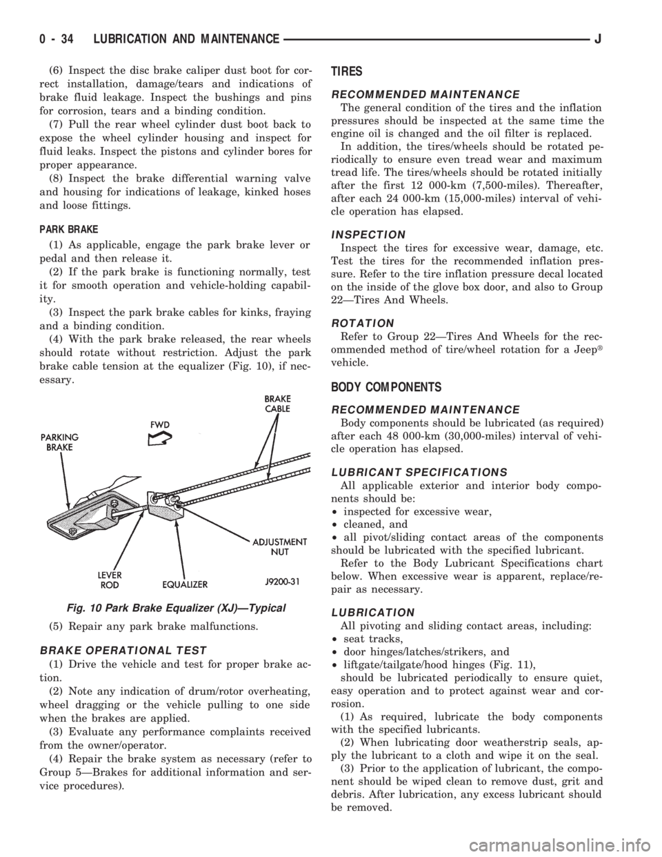
brake cable tension at the equalizer (Fig. 10), if nec-
essary.
(5) Repair any park brake malfunctions.
BRAKE OPERATIONAL TEST
(1) Drive the vehicle and test for proper brake ac-
tion.
(2) Note any indication of drum/rotor overheating,
wheel dragging or the vehicle pulling to one side
when the brakes are applied.
(3) Evaluate any performance complaints received
from the owner/operator.
(4) Repair the brake system as necessary (refer to
Group 5ÐBrakes for additional information and ser-
vice procedures).
TIRES
RECOMMENDED MAINTENANCE
The general condition of the tires and the inflation
pressures should be inspected at the same time the
engine oil is changed and the oil filter is replaced.
In addition, the tires/wheels should be rotated pe-
riodically to ensure even tread wear and maximum
tread life. The tires/wheels should be rotated initially
after the first 12 000-km (7,500-miles). Thereafter,
after each 24 000-km (15,000-miles) interval of vehi-
cle operation has elapsed.
INSPECTION
Inspect the tires for excessive wear, damage, etc.
Test the tires for the recommended inflation pres-
sure. Refer to the tire inflation pressure decal located
on the inside of the glove box door, and also to Group
22ÐTires And Wheels.
ROTATION
Refer to Group 22ÐTires And Wheels for the rec-
ommended method of tire/wheel rotation for a Jeept
vehicle.
BODY COMPONENTS
RECOMMENDED MAINTENANCE
Body components should be lubricated (as required)
after each 48 000-km (30,000-miles) interval of vehi-
cle operation has elapsed.
LUBRICANT SPECIFICATIONS
All applicable exterior and interior body compo-
nents should be:
²inspected for excessive wear,
²cleaned, and
²all pivot/sliding contact areas of the components
should be lubricated with the specified lubricant.
Refer to the Body Lubricant Specifications chart
below. When excessive wear is apparent, replace/re-
pair as necessary.
LUBRICATION
All pivoting and sliding contact areas, including:
²seat tracks,
²door hinges/latches/strikers, and
²liftgate/tailgate/hood hinges (Fig. 11),
should be lubricated periodically to ensure quiet,
easy operation and to protect against wear and cor-
rosion.
(1) As required, lubricate the body components
with the specified lubricants.
(2) When lubricating door weatherstrip seals, ap-
ply the lubricant to a cloth and wipe it on the seal.
(3) Prior to the application of lubricant, the compo-
nent should be wiped clean to remove dust, grit and
debris. After lubrication, any excess lubricant should
be removed.
Fig. 10 Park Brake Equalizer (XJ)ÐTypical
0 - 34 LUBRICATION AND MAINTENANCEJ
Page 40 of 1784
The shocks absorbers dampen jounce and rebound
of the vehicle over various road conditions. The top of
the shock absorbers are bolted to the frame. The bot-
tom of the shocks are bolted to the axle bracket.
The stabilizer bar is used to minimize vehicle front
sway during turns. The spring steel bar helps to con-
trol the vehicle body in relationship to the suspen-
sion. The bar extends across the front underside of
the chassis and connects to the frame rails. Links are
connected from the bar to the axle brackets. Stabi-
lizer bar mounts are isolated by rubber bushings.
The track bar is used to minimize front axle side-
to-side movement. The track bar is attached to a
frame rail bracket and the axle bracket.
The bar uses bushings at both ends.
FRONT DRIVE AXLE
It is not necessary to remove the complete axle
from the vehicle for routine differential service. If
the differential housing or axle shaft tubes are dam-
aged, the complete axle assembly can be removed
and serviced.
For complete drive axle assembly removal and in-
stallation refer to Drive Axle Assembly Replacement
in this Group.
The removable cover provides for servicing without
removing axle from vehicle.
The integral type housing, hypoid gear design has
the centerline of the pinion set above the centerline
of the ring gear.
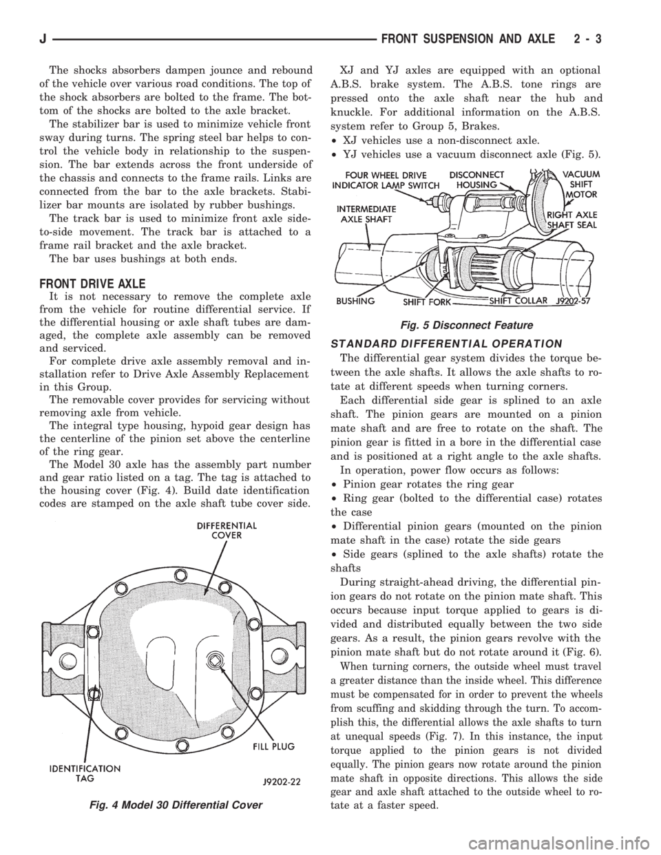
The Model 30 axle has the assembly part number
and gear ratio listed on a tag. The tag is attached to
the housing cover (Fig. 4). Build date identification
codes are stamped on the axle shaft tube cover side.XJ and YJ axles are equipped with an optional
A.B.S. brake system. The A.B.S. tone rings are
pressed onto the axle shaft near the hub and
knuckle. For additional information on the A.B.S.
system refer to Group 5, Brakes.
²XJ vehicles use a non-disconnect axle.
²YJ vehicles use a vacuum disconnect axle (Fig. 5).
STANDARD DIFFERENTIAL OPERATION
The differential gear system divides the torque be-
tween the axle shafts. It allows the axle shafts to ro-
tate at different speeds when turning corners.
Each differential side gear is splined to an axle
shaft. The pinion gears are mounted on a pinion
mate shaft and are free to rotate on the shaft. The
pinion gear is fitted in a bore in the differential case
and is positioned at a right angle to the axle shafts.
In operation, power flow occurs as follows:
²Pinion gear rotates the ring gear
²Ring gear (bolted to the differential case) rotates
the case
²Differential pinion gears (mounted on the pinion
mate shaft in the case) rotate the side gears
²Side gears (splined to the axle shafts) rotate the
shafts
During straight-ahead driving, the differential pin-
ion gears do not rotate on the pinion mate shaft. This
occurs because input torque applied to gears is di-
vided and distributed equally between the two side
gears. As a result, the pinion gears revolve with the
pinion mate shaft but do not rotate around it (Fig. 6).
When turning corners, the outside wheel must travel
a greater distance than the inside wheel. This difference
must be compensated for in order to prevent the wheels
from scuffing and skidding through the turn. To accom-
plish this, the differential allows the axle shafts to turn
at unequal speeds (Fig. 7). In this instance, the input
torque applied to the pinion gears is not divided
equally. The pinion gears now rotate around the pinion
mate shaft in opposite directions. This allows the side
gear and axle shaft attached to the outside wheel to ro-
tate at a faster speed.
Fig. 4 Model 30 Differential Cover
Fig. 5 Disconnect Feature
JFRONT SUSPENSION AND AXLE 2 - 3
Page 41 of 1784
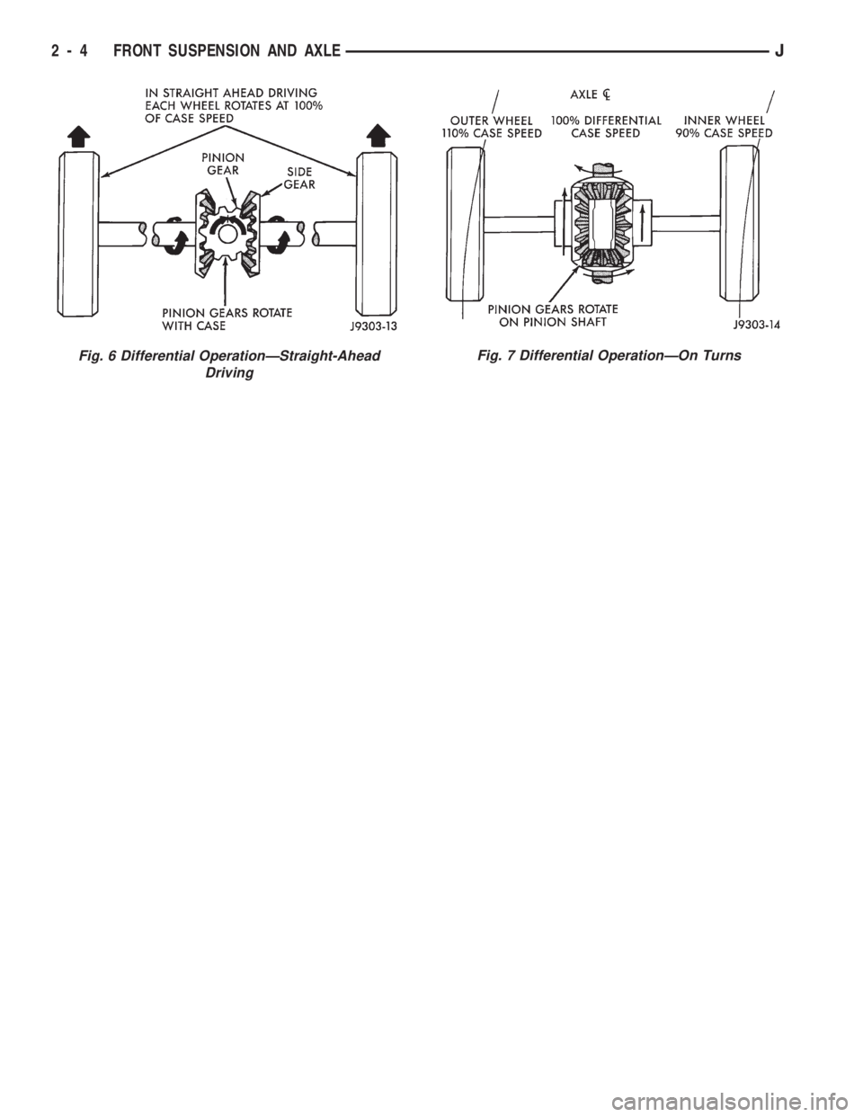
Fig. 6 Differential OperationÐStraight-Ahead
DrivingFig. 7 Differential OperationÐOn Turns
2 - 4 FRONT SUSPENSION AND AXLEJ
Page 53 of 1784
AXLE NOISE/VIBRATION DIAGNOSIS
INDEX
page page
Driveline Snap........................... 17
Gear and Bearing Noise................... 16
General Information....................... 16Low Speed Knock........................ 17
Vibration............................... 17
GENERAL INFORMATION
Axle bearing problem conditions are usually caused
by:
²Insufficient or incorrect lubricant
²Foreign matter/water contamination
²Incorrect bearing preload torque adjustment
²Incorrect backlash (to tight)
When serviced, the bearings must be cleaned thor-
oughly. They should be dried with lint-free shop tow-
els.Never dry bearings with compressed air.
This will overheat them and brinell the bearing
surfaces. This will result in noisy operation after
repair.
Axle gear problem conditions are usually the result
of:
²Insufficient lubrication
²Incorrect or contaminated lubricant
²Overloading (excessive engine torque) or exceeding
vehicle weight capacity
²Incorrect clearance or backlash adjustment
Insufficient lubrication is usually the result of a
housing cover leak. It can also be from worn axle
shaft or pinion gear seals. Check for cracks or porous
areas in the housing or tubes.
Using the wrong lubricant will cause overheating
and gear failure. Gear tooth cracking and bearing
spalling are indicators of this.
Axle component breakage is most often the result
of:
²Severe overloading
²Insufficient lubricant
²Incorrect lubricant
²Improperly tightened components
Overloading occurs when towing heavier than rec-
ommended loads. Component breakage can occur
when the wheels are spun excessively. Incorrect lu-
bricant quantity contributes to breakage. Loose dif-
ferential components can also cause breakage.
Incorrect bearing preload or gear backlash will not
result in component breakage. Mis-adjustment will
produce enough noise to cause service repair before a
failure occurs. If a mis-adjustment condition is not
corrected, component failure can result.
Excessive bearing preload may not be noisy. This
condition will cause high temperature which can re-
sult in bearing failure.
GEAR AND BEARING NOISE
GEAR NOISE
Axle gear noise can be caused by insufficient lubri-
cant. Incorrect backlash, tooth contact, or worn/dam-
aged gears can cause noise.
Gear noise usually happens at a specific speed
range. The range is 30 to 40 mph, or above 50 mph.
The noise can also occur during a specific type of
driving condition. These conditions are acceleration,
deceleration, coast, or constant load.
When road testing, accelerate the vehicle to the
speed range where the noise is the greatest. Shift
out-of-gear and coast through the peak-noise range.
If the noise stops or changes greatly, check for insuf-
ficient lubricant. Incorrect ring gear backlash, or
gear damage can cause noise changes.
Differential side and pinion gears can be checked
by turning the vehicle. They usually do not cause
noise in straight-ahead driving. These gears are
loaded during vehicle turns. If noise does occur dur-
ing vehicle turns, the side or pinion gears could be
worn or damaged. A worn pinion gear mate shaft can
also cause a snapping or a knocking noise.
BEARING NOISE
The axle shaft, differential and pinion gear bear-
ings can all produce noise when worn or damaged.
Bearing noise can be either a whining, or a growling
sound.
Pinion gear bearings have a constant-pitch noise.
This noise changes only with vehicle speed. Pinion
bearing noise will be higher because it rotates at a
faster rate. Drive the vehicle and load the differen-
tial. If bearing noise occurs the pinion rear bearing is
the source of the noise. If the bearing noise is heard
during a coast, front bearing is the source.
Worn, damaged differential bearings usually pro-
duce a low pitch noise. Differential bearing noise is
similar to pinion bearing. The pitch of differential
bearing noise is also constant and varies only with
vehicle speed.
Axle shaft bearings produce noise and vibration
when worn or damaged. The noise generally changes
when the bearings are loaded. Road test the vehicle.
Turn the vehicle sharply to the left and to the right.
This will load the bearings and change the noise
2 - 16 FRONT SUSPENSION AND AXLEJ
Page 54 of 1784
level. Where axle bearing damage is slight, the noise
is usually not noticeable at speeds above 30 mph.
LOW SPEED KNOCK
Low speed knock is generally caused by a worn
U-joint or by worn side-gear thrust washers. A worn
pinion gear shaft bore will also cause low speed
knock.
VIBRATION
Vibration at the rear of the vehicle is usually
caused by a:
²Damaged drive shaft
²Missing drive shaft balance weight
²Worn, out-of-balance wheels
²Loose wheel lug nuts
²Worn U-joint
²Loose spring U-bolts
²Loose/broken springs
²Damaged axle shaft bearings
²Loose pinion gear nut
²Excessive pinion yoke run out
²Bent axle shaft
Check for loose or damaged front-end components
or engine/transmission mounts. These componentscan contribute to what appears to be a rear-end vi-
bration. Do not overlook engine accessories, brackets
and drive belts.
All driveline components should be examined be-
fore starting any repair.
Refer to Group 22ÐTires And Wheels for addi-
tional information involving vibration diagnosis.
DRIVELINE SNAP
A snap or clunk noise when the vehicle is shifted
into gear (or the clutch engaged), can be caused by:
²High engine idle speed
²Loose engine/transmission/transfer case mounts
²Worn U-joints
²Loose spring mounts
²Loose pinion gear nut and yoke
²Excessive ring gear backlash
²Excessive differential side gear-to-case clearance
The source of a snap or a clunk noise can be deter-
mined with the assistance of a helper. Raise the ve-
hicle on a hoist with the wheels free to rotate.
Instruct the helper to shift the transmission into
gear. Listen for the noise, a mechanics stethoscope is
helpful in isolating the source of a noise.
JFRONT SUSPENSION AND AXLE 2 - 17