1994 JAGUAR XJ6 turn signal
[x] Cancel search: turn signalPage 19 of 327

Automatic Transmission (AJ16)
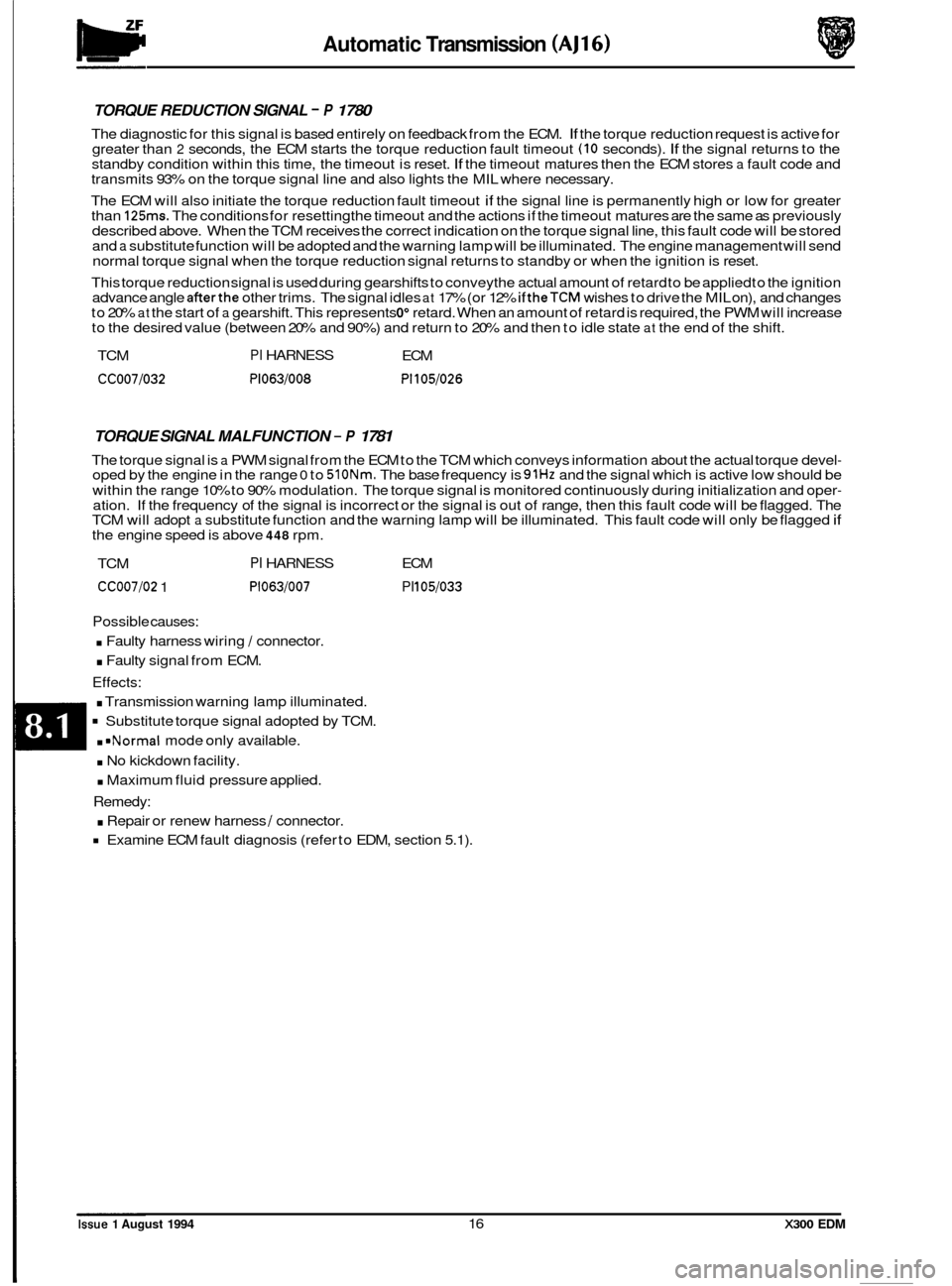
TORQUE REDUCTION SIGNAL - P 1780
The diagnostic for this signal is based entirely on feedback from the ECM. If the torque reduction request is active for
greater than 2 seconds, the ECM starts the torque reduction fault timeout (IO seconds). If the signal returns to the
standby condition within this time, the timeout is reset. If the timeout matures then the ECM stores a fault code and
transmits 93% on the torque signal line and also lights the MIL where necessary.
The ECM will also initiate the torque reduction fault timeout
if the signal line is permanently high or low for greater
than 125ms. The conditions for resetting the timeout and the actions if the timeout matures are the same as previously
described above. When the TCM receives the correct indication on the torque signal line, this fault code will be stored
and
a substitute function will be adopted and the warning lamp will be illuminated. The engine management will send
normal torque signal when the torque reduction signal returns to standby or when the ignition is reset.
This torque reduction signal is used during gearshifts to conveythe actual amount of retard to be applied to the ignition
advance angle
afterthe other trims. The signal idles at 17% (or 12% if theTCM wishes to drive the MIL on), and changes
to 20% at the start of a gearshift. This represents 0" retard. When an amount of retard is required, the PWM will increase
to the desired value (between 20% and 90%) and return to 20% and then to idle state at the end of the shift.
TCM
PI HARNESS ECM
CC007/032 P1063/008 P1105/026
TORQUE SIGNAL MALFUNCTION - P 1781
The torque signal is a PWM signal from the ECM to the TCM which conveys information about the actual torque devel- oped by the engine in the range 0 to 510Nm. The base frequency is 91Hz and the signal which is active low should be
within the range 10% to 90% modulation. The torque signal is monitored continuously during initialization and oper
- ation. If the frequency of the signal is incorrect or the signal is out of range, then this fault code will be flagged. The
TCM will adopt a substitute function and the warning lamp will be illuminated. This fault code will only be flagged if the engine speed is above 448 rpm.
TCM
PI HARNESS ECM
CC007/02 1 P1063/007 PI 105/033
Possible causes:
. Faulty harness wiring I connector.
. Faulty signal from ECM.
Effects:
. Transmission warning lamp illuminated.
Substitute torque signal adopted by TCM.
. =Normal mode only available.
. No kickdown facility.
. Maximum fluid pressure applied.
Remedy:
. Repair or renew harness / connector.
Examine ECM fault diagnosis (refer to EDM, section 5.1).
Issue 1 August 1994 16 X300 EDM
Page 24 of 327

Automatic Transmission (AJ16)
TP ELECTRICAL SIGNAL SYSTEM - P 1791
If the throttle angle signal line is held permanently high or low for more than looms, then this fault will be recognised
and stored. The TCM will adopt the substitute throttle value and turn on the warning lamp. The fault code will only be
stored if the engine speed is greater than 400rpm.
TCM PI HARNESS ECM
CC007/047 P1063/00 1 PI 1041032
Possible causes:
Faulty harness wiring I connection.
. Faulty ECM signal.
Effects:
Transmission warning lamp illuminated.
. MIL illuminated.
Normal mode only available.
Substitute throttle angle adopted.
No kickdown facility.
Remedy:
Repair or renew harness 1 connector.
Examine ECM fault diagnosis (refer to EDM, Section 5.1).
TP SIGNAL SYSTEM RANGE/ PERFORMANCE - P 1790
The throttle signal is a pulse width modulated (pwm) input which runs at a constant frequency of 183 Hz the information is contained in the duty cycle of the signal. If this information is out of range, that is, the duty cycle is less than 5% or
greater than 94%, then the TCM will use a substitute throttle value of 47% and will light the warning lamp and this fault code will be stored. During cranking, this signal is used to convey the engine coolant temperature. The coolant tem- perature signal persistsfor 500 msec after reaching the engine run threshold of 400 rpm. If theTCM does not recognise a valid throttle angle signal afterthis time then a substitute throttle value (47%) will be used and the warning lamp will
be
lit and this fault code will be stored. A fault code will only be stored if the engine speed is greater than 400 rpm. If an out of range coolant temperature is received then a substitute coolant temperature value (77" C) is used but no fault is stored.
X300 EDM 21 Issue 1 August 1994
Page 26 of 327

Automatic Transmission (AJ16)
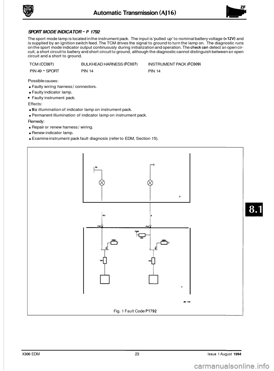
SPORT MODE INDICATOR - P 1792
The sport mode lamp is located in the instrument pack. The input is 'pulled up' to nominal battery voltage (+12V) and
is supplied by an ignition switch feed. The TCM drives the signal to ground to turn the lamp on. The diagnostic runs
on the sport mode indicator output continuously during initialization and operation. The
checkcan detect an open cir- cuit, a short circuit to battery and short circuit to ground, although the diagnostic cannot distinguish between an open
circuit and a short to ground.
TCM
(CC007) BULKHEAD HARNESS (FC007) INSTRUMENT PACK (FCOO9)
PIN 49 - SPORT PIN 14
PIN 14
Possible causes:
. Faulty wiring harness I connectors.
. Faulty indicator lamp.
Faulty instrument pack.
Effects:
. No illumination of indicator lamp on instrument pack.
. Permanent illumination of indicator lamp on instrument pack.
Remedy:
. Repair or renew harness 1 wiring.
. Renew indicator lamp.
0 . Examine instrument pack fault diagnosis (refer to EDM, Section 15).
1
Y.IM
Fig. 1 Fault Code PI792 ~~
X300 EDM 23 Issue 1 August 1994
Page 38 of 327

Automatic Transmission (V12) ~ Pow. rtrain
Engine
Torque Reduction and Malfunction Indication
This signal, to the ECM, has three modes of operation.
1. To indicate normal engine operation to the ECM.
2. During gearshifts, to request reduction of engine torque
3. During fault conditions, to inform the ECM.
During normal operation
theTCM outputs a constant duty cycle signal to the ECM. The signal is changed when torque
reduction is required to indicate to the ECM the degree of ignition retardation necessary. If a fault condition, relating
to OBD
II CARB legislation, occurs the TCM will transmit a signal to the ECM relating this event. The ECM will only
respond to this signal if its duration is 100 milli-seconds or longer.
If the signal from the torque reduction line is either HIGH or LOW for 2 or more seconds the EMS will recognise that
a fault may be present and transmit this information to the TCM.
If the signal from the torque reduction line lasts for 2 or more seconds the EMS will return to normal operation.
Sport Mode Indicator Lamp
The sport mode indicator lamp, mounted on the instrument panel, is illuminate when sport mode is selected and the
ignition switch is ON. Sport mode is selected at a two position switch mounted to the rear of the gear selector assembly.
Gearbox Failure Warning Lamp
The gearbox failure warning lamp, mounted on the instrument panel, is illuminated when afault is detected bytheTCM within the transmission electrical or mechanical systems.
Vehicle Speed (12 cylinder vehicles only)
This output signal is calculated from the transmission output speed and supplied to the ECM as an indication of vehicle
speed.
8.2.5 DIAGNOSTIC LINKS
Diagnostic
L line
One of a two wire interface used to activate stored diagnostic codes for reading by external equipment.
Diagnostic K Line
One of a two-wire interface used to communicate stored diagnostic codes for reading by external diagnostic equip- ment.
X300 EDM 7 Issue 1 August 1994
Page 178 of 327

E I ect r ical IT
SPEED CONTROL
System Description
0 15.3 15.3.1
The speed control system provides an automatic cruise facility, allowing a constant speed to be maintained without
accelerator pedal operation. The system comprises the following components:
0 Electronic control unit
0 Vacuum dump valve
0 Control valve
0 Vacuum pump
0 Mechanical throttle linkage and bellows
0 Selection switch
0 Brake and clutch pedal switches
On selection of speed control, via the switches mounted on the driver's side fascia, the vacuum dump valve, pump and
control valve will energize, creating
a partial vacuum in the bellows assembly. The bellows assembly acts upon the
throttle linkage to adjust throttle position, maintaining vehicle speed at the value when control is selected.
Speed control is determined by the Speed Control Control Module
(SC CM) which monitors a speed signal delivered
from the instrument pack (initially from the ABS rear LH wheel speed sensor) to determine vehicle speed.
Speedcontrol isdisabled, returning control tothedriver,
byoperationofthevacuumdumpvalve,ifanyofthefollowing situations occur: 0
0 Braking
0 Clutch operation (3.2 / 4.0 litre manual transmission vehicles only)
o Drive de-select ie P, N or R (automatic transmissions only, both electronic and hydraulic)
0 Traction control system (where fitted) in operation
0 Rapid speed reduction without braking input, ie double brake switch failure
0 Actual speed drop to 3/4 of cruise setting (eg when towing excessive loads under adverse conditions)
0 Vehicle speeds below w 25 mph
0 Ignition OFF
0 De-selection at switch controls
15.3.2 COMPONENT DESCRlPTlO NS
15.3.2.1 Electronic Control Module
The Speed Control Control Module (SC CM), located behind the fascia, adjacent to the steering column, provides sys- tem control and an interface to external input signals from the instrument pack, gear selector module, traction control
system, control switches, and foot pedal switches. The set speed value is retained in SC CM memory and continuously
compared to actual vehicle speed. Adjustments are made, as necessary, to maintain set speed by control of the vac- uum pump and control valve. Connections to the SC CM are listed in the table on page 3.
X300 EDM 15.3 - 1 Issue 1 August 1994
Page 181 of 327

I3 E I ect r ical
15.3.2.5 Throttle Linkage and Bellows
The throttle linkage and bellows are located adjacent to the throttle body (below supercharger, where fitted) on 6cylin-
der vehicles, or centrally below the injector cover on 12 cylinder vehicles. The bellows expand I contract according
to the pressure drop created by the pump I control valve module, causing the linkage to act upon the throttle body,
controlling vehicle speed.
15.3.2.6
The brake and clutch pedal switches are mounted below the relevant foot pedals. Operation of a pedal, causes subse- quent switch operation, either interrupting the+12Vsupplytothe pneumaticcircuit, orsignalling tothe SC CMto disen- gage speed control, causing the dump valve to open and vent the system, returning speed control to the driver.
Brake and Clutch Pedal Switches
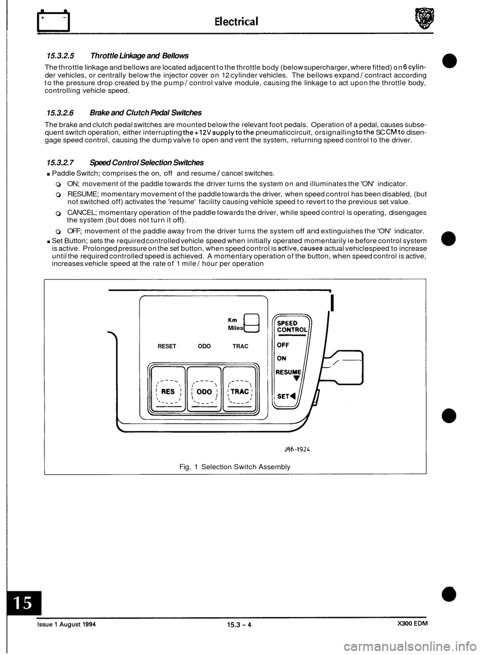
15.3.2.7 Speed Control Selection Switches
. Paddle Switch; comprises the on, off and resume 1 cancel switches.
0 ON; movement of the paddle towards the driver turns the system on and illuminates the 'ON' indicator.
0 RESUME; momentary movement of the paddle towards the driver, when speed control has been disabled, (but
not switched off) activates the 'resume' facility causing vehicle speed to revert to the previous set value.
0 CANCEL; momentary operation of the paddle towards the driver, while speed control is operating, disengages
the system (but does not turn it off).
0 OFF; movement of the paddle away from the driver turns the system off and extinguishes the 'ON' indicator.
. Set Button; sets the required controlled vehicle speed when initially operated momentarily ie before control system
is active. Prolonged pressure on the set button, when speed control is active,causes actual vehiclespeed to increase
until the required controlled speed is achieved. A momentary operation of the button, when speed control is active,
increases vehicle speed at the rate of 1 mile
/ hour per operation
Miles
RESET ODO TRAC
I
JRh-1924
Fig. 1 Selection Switch Assembly
Page 200 of 327

15.4.1.4 Remote Recall
Remote activation of memory positions 1 and 2 can be achieved using the key fob transmitters (one per set of keys).
lfthe vehicle is unlocked using the remote transmitter the stored driving position will be adopted automatically. If the
vehicle is unlocked using the remote transmitter and an exit position is already set the corresponding entry position
will be adopted until the ignition key is inserted, the stored driving position will then be restored. 0 ~
15.4.1.5
Reverse Mirror Dip
On selection of reverse gear and operation of the mirror toggle switch downwards, the passenger side rear view mirror
will automatically tilt downwards to assist reverse parking. Upward adjustment disables reverse dip, a further down- ward adjustment when still in reverse gear reinstates reverse dip. The mirror will return to normal position when any
other gear position is selected.
15.4.2 SYSTEM COMPONENTS
15.4.2.1 Seats
- Driver and Passenger
The driver and passenger seat adjustment systems comprises the following components:
o Fore / aft motor
o Front raise / lower motor
o Rear raise / lower motor
0 Squab recline motor
0 Headrest motor
0 Lumbarpump
0 Squab heater
0 Inner cushion heater
0 Outer cushion heater
0 Heater thermostat
0 Switch pack
o Seat Control Module (SCM)
o Wiring harness
15.4.2.2 Motors
The five seat position adjustment motors are located below the seat cushions (horizontal and vertical adjustment) and
behind the squab (recline and headrest adjustment). Each motor unit incorporates a potentiometer which provides
directional movement position control via feedbackvoltage variations to the SCM. Positional variations are activated
by the SCM in response to signals from switches mounted on the seat switch pack.
15.4.2.3 Lumbar Pump
The lumbar pump, located behind the seat squab allows adjustment of seat rigidity by increasing/decreasing air pres- sure in the lumbar pad. The pump motor is controlled from a switch on theseat switch pack and governed by an in-line
pressure switch.
A solenoid valve is used to regulate air flow to the lumbar pad.
15.4.2.4 Heaters and Thermostats
The two cushion heaters and squab heater are regulated by a single in-line thermostat and operated by a switch
mounted on thecenter console switch pack. Operation of this switch causesthe Body Processor Unit (BPU) to energize a timed input to SCM (for 11 minute f 1) which in turn causes SCM to energize the heater supply. The supply will
remain on until timed out, although the heater circuit will be broken by the thermostat if the set temperature is ex- ceeded.
Note: Heatingcan only occur when the ignition switch is position I1 and the ambient temperature is belowthe thermo- stat pre-set value of 26°C.
X300 EDM 15.4 - 3 Issue 1 August 1994