Page 78 of 327

Climate Control Systems
System Differences
m:
Heater only vehicles do not have the following fitted:
This section applies generally to both air conditioning and heater systems. System specific descriptions, pro-
cedures, tests etc. are indicated.
0 Solar sensor
0 Clutch request and acknowledge circuitry.
0 Refrigerant pressure switch.
0 Control panel - deletion of air conditioning button.
6 cyl. engined vehicles do not have either the electrical load inhibit or the compressor lock sensor.
Heated Front Screen
(HFS) is optional on both air conditioning and heater panel versions.
14.2 COMPONENT DESCRIPTIONS
14.2.1 Control Panel
The control panel (Fig. 1) provides the operator interface with the climate control system.
The control panel communicates with the
A / CCM via a serial data communications link. During each data transfer
cycle the control panel states whether it is an air conditioning or heater version, thus enabling the A/ CCM to control
the system functions accordingly.
Tontrol panel operation is described in detail in the 'Climate Control Systems' section of the VSM.
-
Fig. 1 Control Panel (A / C with Heated front Screen)
J86 - I726
14.2.2 Control Panel Inputs /Outputs
Description I CableColor
I 1 I Output clock I Grey I
2 Output start Grey / Red
3 Input data
in Grey / Yellow
4 Output
data out Grey / Green
5 Output
ignition positive White / Red
6 Output auxiliary positive
White / Blue
7 Output
ground Black
8 Dimmer
Red
9 Dimmer override Red / Green
I 10 I Not connected I- I
I 11 I Not connected I- I
I 12 I Not connected l- I
X300 EDM 3 Issue 1 August 1994
Page 93 of 327

Climate Control Systems
Minimum differential (Red)
Maximum differential (Blue)
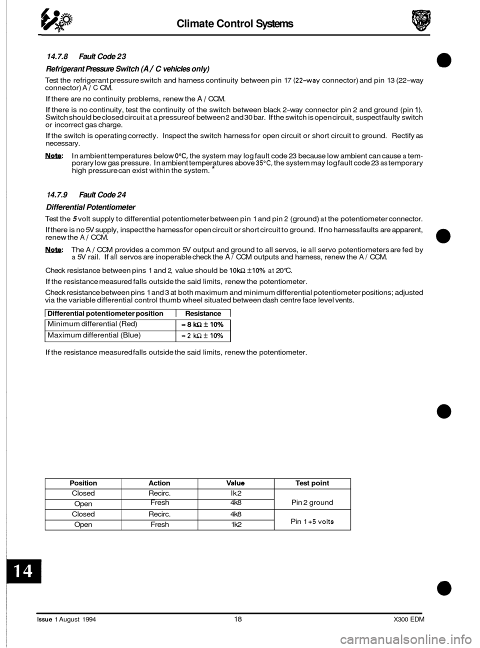
14.7.8 Fault Code 23
Refrigerant Pressure Switch
(A / C vehicles only)
Test the refrigerant pressure switch and harness continuity between pin 17 (22-way connector) and pin 13 (22-way
connector) A / C CM.
If there are no continuity problems, renew the A / CCM.
If there is no continuity, test the continuity of the switch between black 2-way connector pin 2 and ground (pin 1). Switch should be closed circuit at a pressure of between 2 and 30 bar. If the switch is open circuit, suspect faulty switch
or incorrect gas charge.
If the switch is operating correctly. Inspect the switch harness for open circuit or short circuit to ground. Rectify as
necessary.
Nnfe: In ambient temperatures below O"C, the system may log fault code 23 because low ambient can cause a tem- porary low gas pressure. In ambient temperatures above 35"C, the system may log fault code 23 as temporary
high pressure can exist within the system. *
=8WZkIO%
=2 WZf 10%
1 4.7.9 Fault Code 24
Differential Potentiometer
Test the 5 volt supply to differential potentiometer between pin 1 and pin 2 (ground) at the potentiometer connector.
If there is no 5V supply, inspect the harness for open circuit or short circuit to ground.
If no harness faults are apparent,
renew the A / CCM.
1ynf9: The A / CCM provides a common 5V output and ground to all servos, ie all servo potentiometers are fed by a 5V rail. If all servos are inoperable check the A/ CCM outputs and harness, renew the A/ CCM.
Check resistance between pins 1 and
2, value should be IOWZ +10% at 20°C.
If the resistance measured falls outside the said limits, renew the potentiometer.
Check resistance between pins 1 and 3 at both maximum and minimum differential potentiometer positions; adjusted
via the variable differential control thumb wheel situated between dash centre face level vents.
Position
Closed
Open
Closed
Open
I Differential potentiometer position 1 Resistance 1
Action Value Test point
Recirc. lk2
Fresh 4k8 Pin 2 ground
Recirc. 4k8
Pin
1 +5volts Fresh 1 k2
If the resistance measured falls outside the said limits, renew the potentiometer.
a
0
0
Issue 1 August 1994 18 X300 EDM
Page 161 of 327

rl E I ect r i ca I
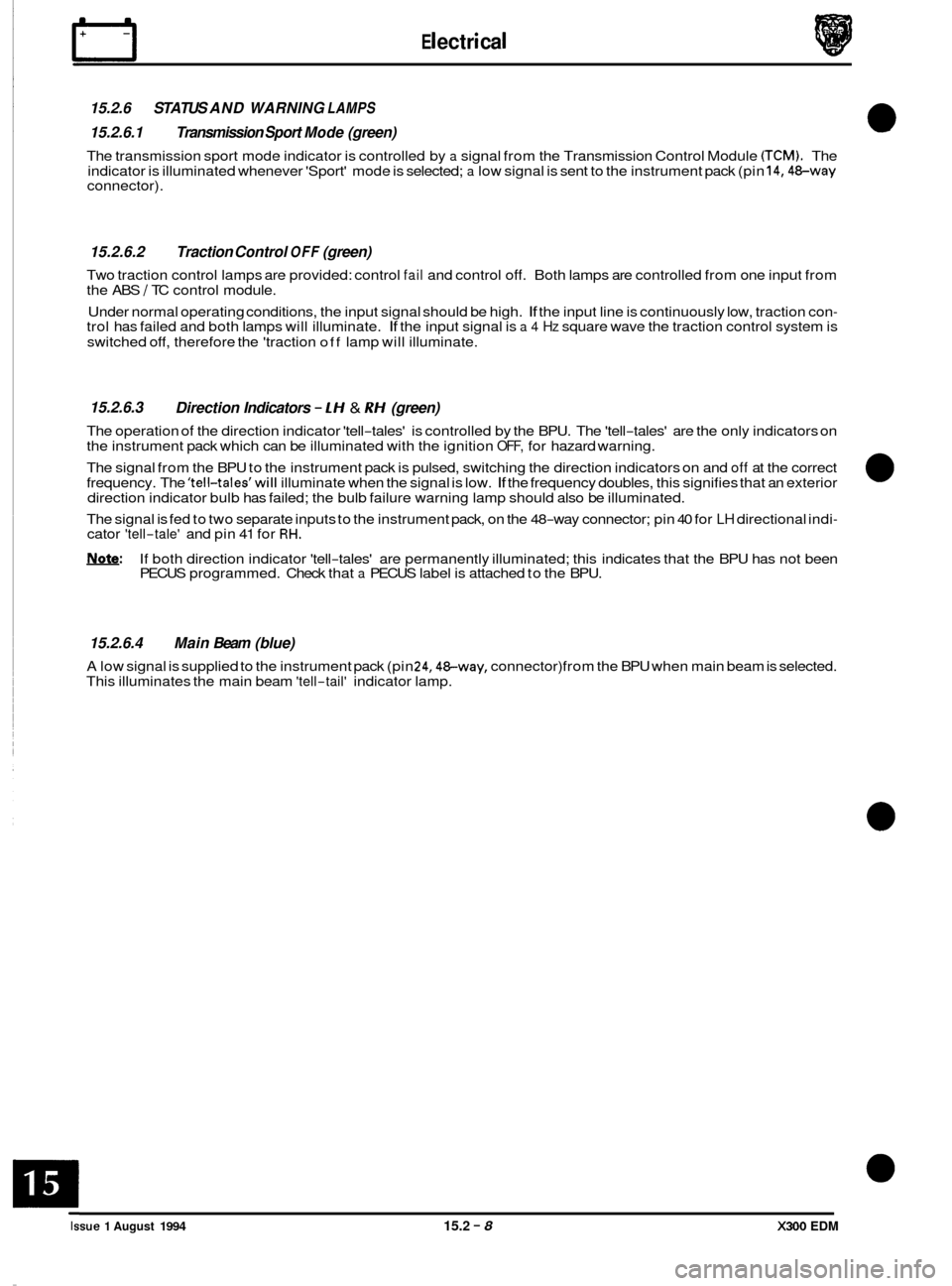
15.2.6 STATUS AND WARNING LAMPS
15.2.6.1 Transmission Sport Mode (green)
The transmission sport mode indicator is controlled by a signal from the Transmission Control Module (TCM). The
indicator is illuminated whenever 'Sport' mode is selected; a low signal is sent to the instrument pack (pin 14,48-way connector).
15.2.6.2 Traction Control OFF (green)
Two traction control lamps are provided: control fail and control off. Both lamps are controlled from one input from
the ABS I TC control module.
Under normal operating conditions, the input signal should be high.
If the input line is continuously low, traction con- trol has failed and both lamps will illuminate. If the input signal is a 4 Hz square wave the traction control system is
switched off, therefore the 'traction
off lamp will illuminate.
15.2.6.3
The operation of the direction indicator 'tell-tales' is controlled by the BPU. The 'tell-tales' are the only indicators on
the instrument pack which can be illuminated with the ignition OFF, for hazard warning.
The signal from the BPU to the instrument pack is pulsed, switching the direction indicators on and
off at the correct
frequency. The 'tell-tales'will illuminate when the signal is low. If the frequency doubles, this signifies that an exterior
direction indicator bulb has failed; the bulb failure warning lamp should also be illuminated.
The signal is fed to two separate inputs to the instrument pack, on the 48
-way connector; pin 40 for LH directional indi- cator 'tell-tale' and pin 41 for RH.
!We: If both direction indicator 'tell-tales' are permanently illuminated; this indicates that the BPU has not been
PECUS programmed. Check that a PECUS label is attached to the BPU.
Direction Indicators - LH & RH (green)
15.2.6.4 Main Beam (blue)
A low signal is supplied to the instrument pack (pin 24,48-way, connector) from the BPU when main beam is selected.
This illuminates the main beam 'tell-tail' indicator lamp.
Issue 1 August 1994 15.2 - 8 X300 EDM
Page 203 of 327
Electrical
15.4.3.1
Connectors AI and A2form the seat internal harness interface. Connectors B1 and B2form thecabin/seat link harness
interface.
Seat Control Module Connector Pins
0
I CONNECTOR B1- 12 PIN. BLUE 1
Pin No. Description Input / Output Signal
1 JDS 'K Line I/O Serial data bus
2 JDS 'L' Line I/O Serial data bus
3 Earth I/P High current
4 Battery supply 1 I/P Supply +VE
X300 EDM Issue 1 August 1994 15.4 - 6