1994 JAGUAR XJ6 trunk
[x] Cancel search: trunkPage 102 of 327

Electrical IT
SECTION CONTENTS
Sub
-Section 15.2 lnsfrumenfs
Subsection Title SRO Page
15.2 ............. Instruments .................................................................... 15.2-1
15.2.1
............ Introduction .................................................................... 15.2-1
15.2.2
............ Instrument Pack Connectors - Pin Locations ......................................... 15.2-3
15.2.3
............ Component Description .......................................................... 15.24
15.2.3.1 .......... Speedometer ................................................................... 15.24
15.2.3.2 .......... Tachometer .................................................................... 15.24
15.2.3.3
.......... Engine Oil Pressure and Warning Lamp ............................................. 15.24
15.2.3.4 .......... Engine Coolant Temperature ...................................................... 15.24
15.2.3.5 .......... Fuel Tank Level Gauge and Warning Lamp .......................................... 15.24
15.2.3.6
.......... Battery Voltage Gauge and Warning Lamp .......................................... 15.24
15.2.3.7
.......... Liquid Crystal Display ........................................................... 15.24
15.2.3.8 .......... Trip Computer .................................................................. 15.2-5
15.2.4
............ Primary Warning Lamps (Illuminated Red) .......................................... 15.2-5
15.2.4.1
.......... Exhaust Temperature ............................................................ 15.2-5
15.2.4.2
.......... Low Oil Pressure ................................................................ 15.2-5
15.2.4.3
.......... Seat Belt ....................................................................... \
15.2-5
15.2.4.4
.......... Trunk Lid Open ................................................................. 15.2-5
15.2.4.5
.......... DoorAjar ...................................................................... 15.2-5
15.2.4.6
.......... Engine Coolant LeveL ............................................................ 15.24
15.2.4.7
.......... SRS Airbag Fault ................................................................ 15.24
15.2.4.8 .......... Charging Fault .................................................................. 15.24
15.2.4.9 .......... Brake System Fault .............................................................. 15.24
15.2.4.10 ......... Bark Brake ..................................................................... 15.24
15.2.5. ........... Secondary Warning Lamps (Illuminated Amber) ...................................... 15.2-7
15.2.5.1
.......... Transmission Fault ............................................................... 15.2-7
15.2.5.2
.......... Washer Fluid Level .............................................................. 15.2-7
15.2.5.3
.......... Bulb Fail ....................................................................... \
15.2-7
15.2.5.4
.......... Traction Control Fail ............................................................. 15.2-7
15.2.5.5
.......... Anti-lock Fail .................................................................. 15.2-7
15.2.5.6
.......... Low Fuel Level ................................................................. 15.2-7
15.2.5.7
.......... Check Engine ................................................................... 15.2-7
15.2.6.1
.......... Transmission Sport Mode ......................................................... 15.2-8
15.2.6.2
.......... Traction Control OFF ............................................................ 15.2-8
15.2.6.3
.......... Direction Indicators ............................................................. 15.2-8
15.2.6.4
.......... Main Beam .................................................................... 15.2-8
15.2.6
............ Status
and Warning Lamps ........................................................ 15.2-8
m
a
0
e
0
X300 EDM ii Issue 1 August 1994
Page 158 of 327

15.2.3.8 Trip Computer
The instrument pack provides the trip computer functions, selected via the momentary stalk input and two action in- puts: 'Reset' and 'Odo'.
The signal used for each function are:
Distance:
Computed from the speed signal from the ABS control module.
Average Speed
Computed from the speed signal from the ABS control module.
Fuel Used
Computed from a pulsed signal from the engine management system.
Average Fuel Consumption
Computed from the speed signal and the fuel used signal.
Range
Computed from the speed signal, the fuel used signal and fuel level.
instantaneous Fuel
Computed from the speed signal and the fuel used signal.
15.2.4 PRIMARY WARNING LAMPS - ILLUMINATED RED
15.2.4.1 Exhaust Temperature (Japan only)
The exhaust temperature input (pin 23,48 way connector) is provided by the catalyst switching module (pin 6), which
pulls the line low when a fault occurs.
15.2.4.2 Low Oil Pressure
This signal comes direct from the variable resistance type oil pressure sensor. The sensor resistancevalues range from
7552 to 310Q.
15.2.4.3 Seat Selt
The seat belt input (pin 15,48 way connector) is provided by the seat belt stalk switch, via the body processor unit
(pin 26).
The seat belt lamp will illuminate when
a low signal is seen on the instrument pack input.
15.2.4.4 Trunk Lid Open
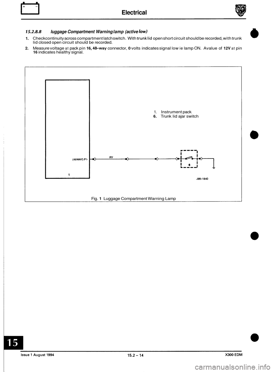
A microswitch located in the trunk lid lock provides a signal (pin 16,4&wayconnector) causing the trunk lid open indi- cator to illuminate whenever the trunk lid is opened or not closed correctly.
The trunk lid open indicator will illuminate when
a low signal is seen on the instrument pack input.
15.2.4.5 Door Ajar
Switches located in each door closing mechanism supply signals to indicate when any door is either open, or has not
been closed correctly. The system operates from two signals; an input from the driver's door (pin 46, 48-way con- nector) or a combined signal input from the passenger doors (pin 47,4&way connector).
The door ajar lamp will illuminate when
a low signal is detected on either of the two inputs.
X300 EDM 15.2 - 5 Issue 1 August 1994
Page 167 of 327

IT Electrical
15.2.8.8
1.
2.
luggage Compartment Warning lamp (active low)
Checkcontinuity across compartment latch switch. With trunklid open short circuit should be recorded, with trunk
lid closed open circuit should be recorded.
Measure voltage
at pack pin 16, &way connector, 0 volts indicates signal low ie lamp ON. Avalue of 12V at pin 16 indicates healthy signal.
(48 WAY) Pli
1
1. Instrument pack 6. Trunk lid ajar switch
J86-1840
Fig. 1 Luggage Compartment Warning Lamp