1994 JAGUAR XJ6 warning
[x] Cancel search: warningPage 27 of 327

lw Automatic Transmission (AJ16)
SYSTEM VOLTAGE MALFUNCTION - P 1794
The TCM monitors the supply voltage and will log this fault if the voltage is less than 10.5V when the engine speed is
greaterthan 1600rpm. This fault code is unlikelyto becaused by afault within theTCM and assuch thevehicle harness
and fuses etc. should be completely tested before the TCM is condemned.
Possible causes:
. Blown fuses.
. Faulty harness wiring /connections.
Effects:
Transmission default settings adopted.
. MIL illuminated.
Transmission warning lamp illuminated.
. Maximum fluid pressure available.
. Limp home mode applied.
Remedy:
Examine fuse F14 in LH heelboard fuse-box. Renew (if necessary) after determining cause of rupture.
. Repair or renew harness / connector.
KICK-DOWN SWITCH SYSTEM - P 1796
The diagnostic check on the mode switch input is a plausibility check which is performed continuously while in oper- ation. A fault is determined when kickdown is seen when the throttle angle is less than 50%. However a fault will only
be logged if the output speed is greater than 256 rpm. No fault is logged if there is already a throttle signal fault. The
kickdown switch is located on the floor under the accelerator pedal and is operated when the throttle is fully open (ap- prox 90%). It is a normally open switch with one contact permanently to ground and the other is a signal to the TCM.
The signal wire is routed through the bulkhead harness and the gearbox harness to the TCM.
LHD
(FCO19) PIN 2 GROUND PIN 1 KD
SIGNAL
RHD
(CA074) PIN 2 GROUND PIN 1 KD
SIGNAL
Possible causes
. Faulty harness wiring /connections.
. Faulty switch (or switch adjustment).
Effects:
No kickdown facility.
Remedy:
. Repair or renew harness /connector.
. Re-adjust or renew switch.
0
0
0
Q
Issue 1 August 1994 24 X300 EDM
Page 29 of 327

Automatic Transmission (AJ16)
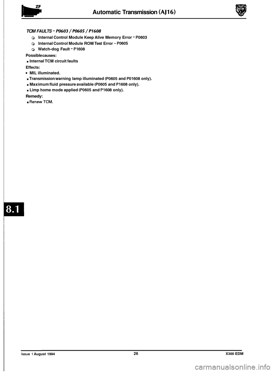
TCM FAULTS - PO603 / PO605 / P1608
0 Internal Control Module Keep Alive Memory Error - PO603
0 Internal Control Module ROM Test Error - PO605
0 Watch-dog Fault - PI608
Possible causes:
. Internal TCM circuit faults
Effects:
MIL illuminated.
. Transmission warning lamp illuminated (PO605 and PO1608 only).
. Maximum fluid pressure available (PO605 and PI608 only).
. Limp home mode applied (PO605 and PI608 only).
Remedy:
. RenewTCM.
Issue 1 August 1994 26 X300 EDM
Page 38 of 327

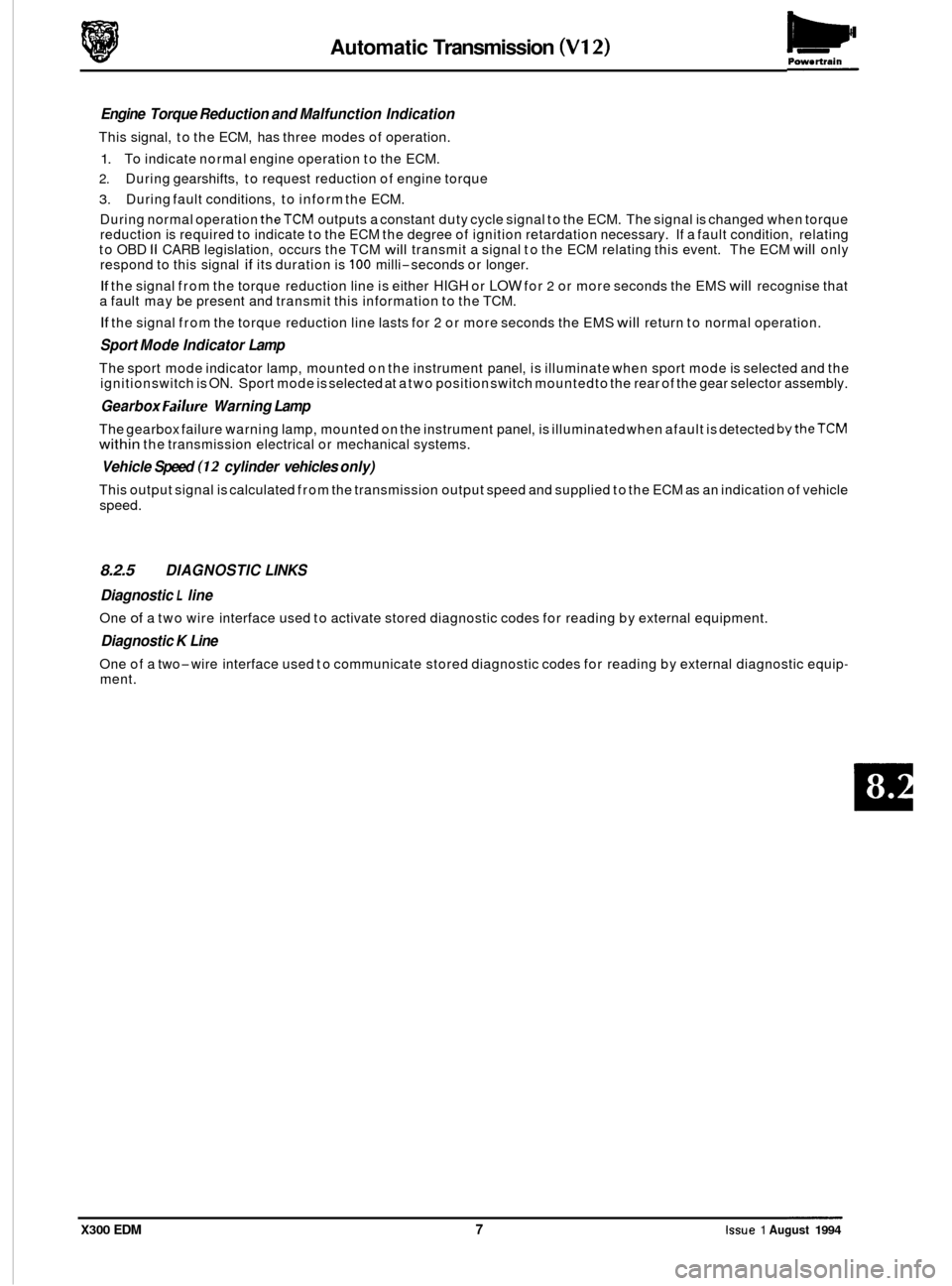
Automatic Transmission (V12) ~ Pow. rtrain
Engine
Torque Reduction and Malfunction Indication
This signal, to the ECM, has three modes of operation.
1. To indicate normal engine operation to the ECM.
2. During gearshifts, to request reduction of engine torque
3. During fault conditions, to inform the ECM.
During normal operation
theTCM outputs a constant duty cycle signal to the ECM. The signal is changed when torque
reduction is required to indicate to the ECM the degree of ignition retardation necessary. If a fault condition, relating
to OBD
II CARB legislation, occurs the TCM will transmit a signal to the ECM relating this event. The ECM will only
respond to this signal if its duration is 100 milli-seconds or longer.
If the signal from the torque reduction line is either HIGH or LOW for 2 or more seconds the EMS will recognise that
a fault may be present and transmit this information to the TCM.
If the signal from the torque reduction line lasts for 2 or more seconds the EMS will return to normal operation.
Sport Mode Indicator Lamp
The sport mode indicator lamp, mounted on the instrument panel, is illuminate when sport mode is selected and the
ignition switch is ON. Sport mode is selected at a two position switch mounted to the rear of the gear selector assembly.
Gearbox Failure Warning Lamp
The gearbox failure warning lamp, mounted on the instrument panel, is illuminated when afault is detected bytheTCM within the transmission electrical or mechanical systems.
Vehicle Speed (12 cylinder vehicles only)
This output signal is calculated from the transmission output speed and supplied to the ECM as an indication of vehicle
speed.
8.2.5 DIAGNOSTIC LINKS
Diagnostic
L line
One of a two wire interface used to activate stored diagnostic codes for reading by external equipment.
Diagnostic K Line
One of a two-wire interface used to communicate stored diagnostic codes for reading by external diagnostic equip- ment.
X300 EDM 7 Issue 1 August 1994
Page 52 of 327

Automatic Transmission (V12) Powertrain
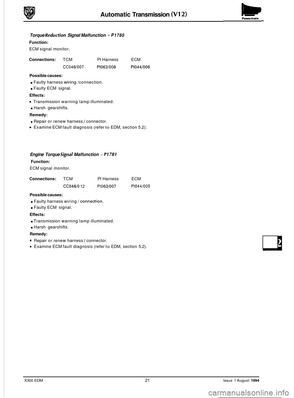
Torque Reduction Signal Malfunction - P1780
Function:
ECM signal monitor.
Connections: TCM PI Harness ECM
CC048/007 P1063/008 P1044/006
Possible causes:
. Faulty harness wiring /connection.
. Faulty ECM signal.
Effects:
. Harsh gearshifts.
Remedy:
. Repair or renew harness / connector.
Examine ECM fault diagnosis (refer to EDM, section 5.2).
Transmission
warning lamp illuminated.
Engine Torque Signal Malfunction - P1781
Function:
ECM signal monitor.
Connections: TCM PI Harness
CC048/0 12 P1063/007
ECM
P1044/005
Possible causes:
. Faulty harness wiring /connection.
. Faulty ECM signal.
Effects:
. Transmission warning lamp illuminated.
. Harsh gearshifts.
Remedy:
Repair or renew harness / connector.
Examine ECM fault diagnosis (refer
to EDM, section 5.2).
X300 EDM 21 Issue 1 August 1994
Page 66 of 327

Brakes
12.2 SYSTEM DESCRIPTION
The anti-lock braking system (ABS) and traction control system CTC) comprise the following components:
0 Hydraulic module: incorporating a pump, motor, low pressure accumulator, valve block, and either an ABS Con-
trol Module (ABS CM) or an ABS / TC Control Module (ABS / TC CM).
U!&: Within the hydraulic module are contained the electro-hydraulic inlet and outlet valves which regulate brake
system pressure.
o Four wheel speed sensors; hub end mounted.
0 Three warning indicators plus a Brake Warning Lamp and a Traction OFF / ON switch; fascia mounted.
0 Throttle valve flap positioning mechanism; mounted adjacent to the hydraulic module.
0 Various auxiliary inputs; providing information to ABS / TC CM.
0 Diagnostic IS0 communication BUS input / output link.
The solenoid operated hydraulic valves
are activated by signals, from the ABS /TC CM, which are generated using in-
formation received from the wheel speed sensors.
For vehicles without traction control thevalves operate on threecircuits, two front and one rear, as necessaryto prevent
wheel locking during braking. Brake pressure is modulated individually
at the front wheels and collectively at the rear.
Rear wheel control operates
a 'select low' principle such that locking in either wheel is sensed, and controlled brake
pressure is applied to both wheels.
Vehicles with traction control fitted have
all four wheels individually controlled allowing selective regulation of tractive
and braking force to each wheel as necessary when traction control is in operation.
The ABS
/ TC system as a whole is monitored constantly by the ABS / TC CM and is disabled (switched off until fault
is rectified) automatically when certain failures are identified. In the event of
a failure being detected the ABS and TC
MIL lamps, located on the instrument panel will illuminate. Full boosted brake operation and normal acceleration con- trol is available when ABS /TC is disabled. The system will be disabled when the following conditions occur:
0 Valve failure.
0 Sensor failure.
0 Main driver failure (internal ABS / TC CM fault).
0 Redundancy error (internal ABS / TC CM fault).
0 Over-voltage.
0 Pump motor failure.
0 Throttle valve actuator motor failure.
In the event
of under-voltage both ABS and TC will be disabled and the ABS andTC MIL lamps on the instrument panel
will illuminate.
U!&: The TC MIL lamp will only illuminate providing a voltage is still present at pin 15 'IGN FEED'
Throttle potentiometer failure will disable the TC function only and illuminate the TC MIL lamp.
The
moduleABS/TC CM is activated when ignition is ON, after an initiation period of approximately 1.7 seconds. After
this time delay the control module is ready to process signals provided from the various input sources and, using the
software defined algorithm, control the electrical and hydraulic circuits.
The inductive sensors attached to each of the four wheels provide speed signals to the ABS
/ TC CM. These signals are processed by ABS/TC CM giving comparison between individual wheel speeds, controlling braking or traction as
necessary and generating a pulse to drive the speedometer. Each sensor is monitored for open and short circuit failure,
causing disabling of ABS / TC on detection of a fault condition.
Issue 1 August 1994 2 X300 EDM
Page 68 of 327

I I I I I I I I
I
I
I 11 I I
I
I
I I P24 1
I
I
I
I
I I I I I I I I
I
I
I
P19: 5
P3-6
7
8
I I I I P28 I-+ 9 10
I P15t T
I
I I I
I
,t I
I
I I I I I I I I
I
I I I
1. Throttle flap actuator 2. Throttle position sensor 3. Cruise control inhibit (when traction control in operation) 4. Traction OFF / ON switch 5. Not Used 6. Gearshift inhibit (when traction control in operation) 7. Wheel speed sensors 8. Battery voltage input
9 IS0 communication BUS IO. Ignition voltage input
1 1. Speedometer signal 12 ABS MIL lamp 13. TCS MIL lamp 14. Traction control OFF lamp 15. Brake warning lamp 16. Brake fluid level switch 17. Stop lamp switch
Fig.
1 Anti-lock braking system and traction
control
-schematic diagram
0
0
Issue 1 August 1994 4 X300 EDM
Page 70 of 327

Brakes
12.4 SYSTEM FAULT INDICATION
Fault Indication:
ABS MIL lamp is still illuminated after ignition switch on and instrument pack self test.
h:
Possible causes
Fuses blown.
Faulty wheel speed sensor or harness.
Faulty wiring.
Faulty ABS
/ TC CM.
It is likely that theTC MIL lamp and Traction OFF lamp will also illuminate on vehicles with traction control fitted.
Fault Diagnosis
On the first ignition cycle after afault has been sucessfully diagnosed and corrected the vehicle must bedriven to a speed above 20kph (12.5 mile/ h) before warning lamps will extinguish. If lamps remain on after this exer- cise repeat fault diagnosis.
. Check fuses (F7) in battery feed lines and (F16) in ignition line. Battery fuses are located in the left and right hand
. Unbolt 28 way multi-plug connector from ABS / TC CM.
. Measure resistance across each wheel speed sensor.
No - Unplug sensor flying lead and re-measure sensor resistance.
N&:
heelboard fuse boxes. The ignition supply fuse is located in the left hand heelboard fuse box.
Is value measured 1 10052, f 50%?
Rear sensor connectors are located beneath the rear seat. Seat must be removed to gain access to connector.
Forward sensor connectors are located adjacent to the hood catch bracket.
Is value now within range?
Yes
- Examine harness between ABS I TC CM and sensor.
No - Renew sensor.
= Check continuity to ground from ABS 1 TC CM harness connections 13 and 14. If value is much greater than 0.152
renew harness.
. With the ignition switch ON, measure voltage between ABS /TC CM harness connection 14 and connections 1 and 2 respectively. If value is not approximately equivalent to battery voltage renew harness.
. With the ignition switch ON, measure voltage between ABSITC CM harness connections14 and 15. If value is not
approximately equivalent to battery voltage renew harness.
Renew ABS /TC CM if fault is not located during the above procedures.
fault Indication:
ABS MIL lamp illuminates at 20 kph.
m:
Possible Causes
Fuses blown.
Faulty hydraulic module pump
/ motor unit or circuitry.
Faulty ABS
/ TC CM.
Fault Diagnosis
Check fuses.
. Disconnect pump / motor unit and measure resistance across two pin connector. Measured value should be in the
. Unbolt 28-way connector from ABS /TC CM and measure voltage between harness connections1 and 14. If value
. Renew ABS 1 TC CM if fault is not located during the above procedures.
It is IikelythattheTCMILlampandTraction OFFlampwill also illuminateonvehicleswithtractioncontrolfitted.
region of 0.852. Renew unit if excessive resistance or short circuit is recorded.
is not approximately equal to battery volts renew harness.
Issue 1 August 1994 X300 EDM
Page 102 of 327

Electrical IT
SECTION CONTENTS
Sub
-Section 15.2 lnsfrumenfs
Subsection Title SRO Page
15.2 ............. Instruments .................................................................... 15.2-1
15.2.1
............ Introduction .................................................................... 15.2-1
15.2.2
............ Instrument Pack Connectors - Pin Locations ......................................... 15.2-3
15.2.3
............ Component Description .......................................................... 15.24
15.2.3.1 .......... Speedometer ................................................................... 15.24
15.2.3.2 .......... Tachometer .................................................................... 15.24
15.2.3.3
.......... Engine Oil Pressure and Warning Lamp ............................................. 15.24
15.2.3.4 .......... Engine Coolant Temperature ...................................................... 15.24
15.2.3.5 .......... Fuel Tank Level Gauge and Warning Lamp .......................................... 15.24
15.2.3.6
.......... Battery Voltage Gauge and Warning Lamp .......................................... 15.24
15.2.3.7
.......... Liquid Crystal Display ........................................................... 15.24
15.2.3.8 .......... Trip Computer .................................................................. 15.2-5
15.2.4
............ Primary Warning Lamps (Illuminated Red) .......................................... 15.2-5
15.2.4.1
.......... Exhaust Temperature ............................................................ 15.2-5
15.2.4.2
.......... Low Oil Pressure ................................................................ 15.2-5
15.2.4.3
.......... Seat Belt ....................................................................... \
15.2-5
15.2.4.4
.......... Trunk Lid Open ................................................................. 15.2-5
15.2.4.5
.......... DoorAjar ...................................................................... 15.2-5
15.2.4.6
.......... Engine Coolant LeveL ............................................................ 15.24
15.2.4.7
.......... SRS Airbag Fault ................................................................ 15.24
15.2.4.8 .......... Charging Fault .................................................................. 15.24
15.2.4.9 .......... Brake System Fault .............................................................. 15.24
15.2.4.10 ......... Bark Brake ..................................................................... 15.24
15.2.5. ........... Secondary Warning Lamps (Illuminated Amber) ...................................... 15.2-7
15.2.5.1
.......... Transmission Fault ............................................................... 15.2-7
15.2.5.2
.......... Washer Fluid Level .............................................................. 15.2-7
15.2.5.3
.......... Bulb Fail ....................................................................... \
15.2-7
15.2.5.4
.......... Traction Control Fail ............................................................. 15.2-7
15.2.5.5
.......... Anti-lock Fail .................................................................. 15.2-7
15.2.5.6
.......... Low Fuel Level ................................................................. 15.2-7
15.2.5.7
.......... Check Engine ................................................................... 15.2-7
15.2.6.1
.......... Transmission Sport Mode ......................................................... 15.2-8
15.2.6.2
.......... Traction Control OFF ............................................................ 15.2-8
15.2.6.3
.......... Direction Indicators ............................................................. 15.2-8
15.2.6.4
.......... Main Beam .................................................................... 15.2-8
15.2.6
............ Status
and Warning Lamps ........................................................ 15.2-8
m
a
0
e
0
X300 EDM ii Issue 1 August 1994