Page 162 of 327

15.2.7 FAULT DIAGNOSIS
15.2.7.1 Active High /Low Inputs
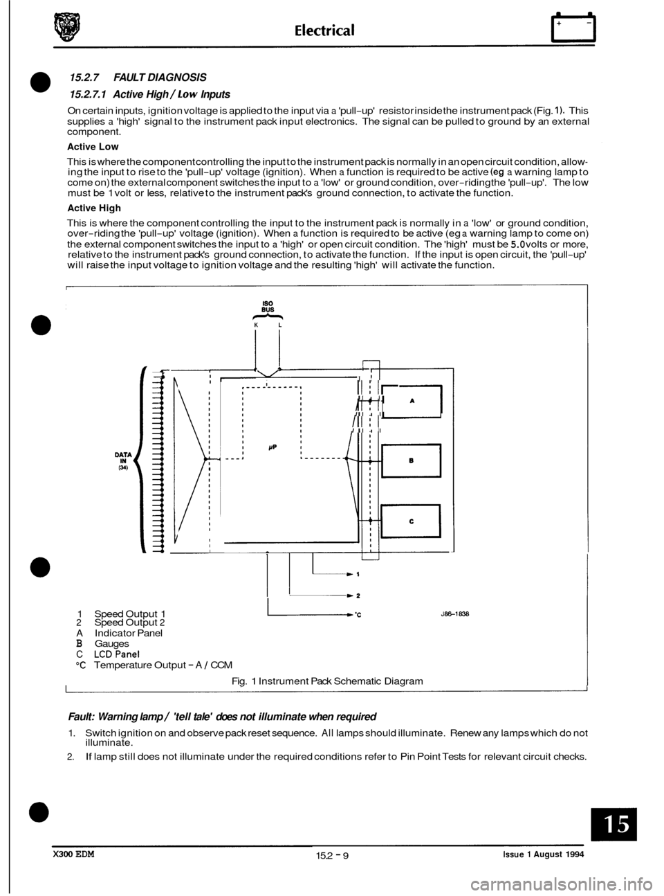
On certain inputs, ignition voltage is applied to the input via a 'pull-up' resistor inside the instrument pack (Fig. 1). This
supplies
a 'high' signal to the instrument pack input electronics. The signal can be pulled to ground by an external
component.
Active Low
This is where the component controlling the input to the instrument pack is normally in an open circuit condition, allow- ing the input to rise to the 'pull-up' voltage (ignition). When a function is required to be active (eg a warning lamp to
come on) the external component switches the input to a 'low' or ground condition, over-riding the 'pull-up'. The low
must be 1 volt or less, relative to the instrument pack's ground connection, to activate the function.
Active High
This is where the component controlling the input to the instrument pack is normally in a 'low' or ground condition,
over-riding the 'pull-up' voltage (ignition). When a function is required to be active (eg a warning lamp to come on)
the external component switches the input to
a 'high' or open circuit condition. The 'high' must be 5.0 volts or more,
relative to the instrument pack's ground connection, to activate the function. If the input is open circuit, the 'pull-up'
will raise the input voltage to ignition voltage and the resulting 'high' will activate the function.
-&
60
eus KL
* \/ I I! I
I ~
I
I I
1
Ill I I '
Ill I I
I
w1
-2
1
Speed Output 1 L .C 2 Speed Output 2
A Indicator Panel B Gauges
C LCDPanel
"C Temperature Output - A 1 CCM
Fig.
1 Instrument Pack Schematic Diagram
JEE-1838
Fault: Warning lamp / 'tell tale' does not illuminate when required
1.
2.
Switch ignition on and observe pack reset sequence. All lamps should illuminate. Renew any lamps which do not
illuminate.
If lamp still does not illuminate under the required conditions refer to Pin Point Tests for relevant circuit checks.
X300 EDM Issue 1 August 1994 15.2 - 9
Page 165 of 327
rl Electrical
15.2.8.6
1.
2.
3.
4.
Door I Pack pin connection I Switch connection
Driver 146,48-way I06
Door Open Warning lamp (Active low)
Close all four doors and turn ignition to ON.
Open each door in turn, checking that lamp illuminates.
On identification of non
-illumination, check continuity across suspect door switch, door closed -switch open cir- cuit, door open -switch short circuit.
If switch tests correctly check continuity from pack connector to the relevant door switch (see table below for pin
numbers).
I Passenger - front 147,4&way 118 I
Passenger - rear left 147,4&way I6L
Passenger - rear right I47,4&way I6R
(48 WAY) P4
(48 WAY) P4
1. Instrument pack
2. Driver’s door ajar switch 3. Passenger door ajar (front)
4.
5.
Passenger door ajar (RH rear)
Passenger door ajar
(LH rear)
1
Fia. 1 Door ODen Indication
J@6-1839
Page 166 of 327
Electrical
15.2.8.7 fxhausf Temperafure Warning lamp (Active Low -Japan Only)
U: This lamp is present in all vehicle instrument packs but only Japanese market cars have the sensor circuitry
installed and connected. The lamp will be illuminated during instrument pack reset sequence
at each ignition
cycle.
1. Ensure harness wiring is intact from instrument pack pin 23 (48-way connector) to catalyst switching module and
from switching module to each thermocouple.
2. Check continuity across each thermocouple, renew if open circuit is recorded.
3. Measure voltage at pack pin
23,48-way connector, 0 volts indicates signal low ie lamp ON. A value of 12V at pin 15 indicates healthy signal, or no sensing circuitry fitted.
I 20
L
I WG
Exhaust temperature sensors
*+12V present only when ignition ON
'IS24
1. Instrument pack 20. Catalyst switching module
21. Thermocouple
J86-1900
Fig. 1 Exhaust Temperature
x300 EDM 15.2 - 13 Issue 1 August 1994
Page 167 of 327
IT Electrical
15.2.8.8
1.
2.
luggage Compartment Warning lamp (active low)
Checkcontinuity across compartment latch switch. With trunklid open short circuit should be recorded, with trunk
lid closed open circuit should be recorded.
Measure voltage
at pack pin 16, &way connector, 0 volts indicates signal low ie lamp ON. Avalue of 12V at pin 16 indicates healthy signal.
(48 WAY) Pli
1
1. Instrument pack 6. Trunk lid ajar switch
J86-1840
Fig. 1 Luggage Compartment Warning Lamp
Page 168 of 327
Electrical
15.2.8.9
1.
2.
Seat Self Warning Indicator (acfive low)
Check seat belt stalk switch for continuity across pins when belt is unlatched, when latched open should be re- corded. Ensure secure ground from switch pin ID
Measure voltage
at pack pin 15,48-way connector, 0 volts indicates signal low ie lamp ON. A value of 12V at pin
15 indicates healthy signal.
(48 WAY) Pl
I
I
I
1. Instrument pack
9. Body processor unit
20. Catalyst switching module
Fig. 1 Seat Belt Indication
X300 EDM 15.2 - 15 Issue 1 August 1994