1994 JAGUAR XJ6 wiper
[x] Cancel search: wiperPage 67 of 327

Brakes (a)
The input frequency of each sensor signal is translated, by the ABS /TC CM, into a comparable wheel speed. Should
any sensed speed be in excess of 330 km / h the relevant sensor is designated 'faulty' and ABS /TC control disabled.
Similarly ABS/TCcontrol is inhibited (switched off until fault condition is cleared) at speeds up to 40 km/ h whenfre- quency fluctuations are detected that are inconsistent with wheel rotation. At speeds above 40 km / h both systems
are disabled when inconsistencies are detected.
Traction control (where fitted) is achieved by using
a small motor and pulley arrangement to adjust the position of the
throttle flap. Under normal operating conditions the system is enabled by default. Operation of the Traction OFF / ON switch, located on the RH side of the fascia switch pack, disables the system and illuminates the TRACTION OFF lamp
located in the instrument pack.
Control is effected to prevent wheel spin by regulating (reducing) the throttle flap position, irrespective of the acceler
-
ator pedal position, using sensor signal comparisons and applying braking force to the wheel affected. Precise posi- tioning of the flap is achieved by monitoring the position of a throttle position sensor. When traction control is
requested
a gearshift inhibit signal is transmitted to the traction control module and cruise control (if selected) is dis- abled.
1
2
3
4
Battery positive feed (via fuse F7,located in the left-hand 'A' post lower fuse-box).
Battery positive feed (via fuse
F7,located in the right-hand 'A' post lower fusebox).
Gearshift inhibit
- during traction control.
Cruise control inhibit
- during traction control.
5/6 Wheel sensor
- LHF
7/8 Wheel sensor
- RHF
9/10 Wheel sensor
- LHR
Control Module Connections
Control module connections numbering 1 - 28, inclusive, provide the necessary input / output signals to enable the
module to control and monitor ABS / TC operation.
Connections are as follows:
13 Ground
14 Ground
15
16
17
18
19 Not used
20 Brake pedal switch.
21
22
23
24
25
26 Throttle position sensor wiper.
27 Throttle position sensor ground.
28 Diagnostic
IS0 communication bus.
Ignition
feed
- monitoring battery voltage to ignition switch.
Throttle valve actuator motor
- battery voltage reference.
Throttle valve actuator motor switching
-during traction control.
Traction inhibit
- via traction OFF / ON switch.
ABS MIL
- malfunction indicator lamp.
ABS ground
- illuminates ABS MIL lamp if ABS /TC CM connector loose or not fitted.
TC MIL
- malfunction indicator lamp.
RL out
- LHR wheel sensor signal drive pulse to speedometer.
Throttle position sensor
5V supply.
I 1 11/12 1 Wheel sensor - RHR 1
X300 EDM 3 Issue 1 August 1994
Page 69 of 327

Brakes (a)
12.3 COMPONENT DESCRlPTlONS
ABS / TC CM (3 Fig. 1)
The ABS / TC CM, located just below the hydraulic valve
block on the bulkhead, is the system controller and pro-
cesses all thevarious information supplied from the external
sensors and probes. The unit monitors ABS / TC operation
giving fault indication and disabling the systems when de- fects are detected. The unit is self testing and cannot be fault
diagnosed beyond 'black box' level i.e. faulty module. Sys-
tem fault codes are stored in a non-volatile memory for in- terrogation by external diagnostic equipment.
Solenoid Valves (2 Fig. 1)
The solenoid operated hydraulic valves, located within the
hydraulic module valve block, regulate the supply of pres- sure to the braking circuits allowing individual control of all wheels with a full ABS /TC system.
Nnfe: For ABS only, the driving (rear) wheels are con-
trolled by a common braking circuit.
The traction control system isolating valve has the
same characteristics as
a normally open valve. a
Hydraulic Pump /Motor Unit (1 Fig. 1)
This unit, located above the hydraulic valve block, ensures
that brake fluid is transmitted around the system at the cor- rect operating pressure. The 250W ds. motor draws 32A
current at peak operation and has an internal resistance of 0.m.
Wheel Speed Sensors (Fig. 2)
The four wheel speed sensors are identical in function and
construction. Wheel rotation creates the signal within the
sensor. This signal is supplied to the ABS /TC
CM where it provides wheel speed information. The sensor coil has a re- sistance value of 1.1 k Q and will have a voltage of 2.5V pres- ent on each connecting pin when the vehicle is stationary.
Throttle Flap Actuator Motor / Position Sensor (Fig. 3)
The throttle flap actuator motor, mounted adjacent tothe hy- draulic control unit, adjusts throttle position, irrespective of
accelerator pedal position, by regulating throttle opening
when traction control is demanded. The actuator motor
nominal 12V terminal voltage is supplied by ABS
/ TC CMduring normal operation. The motor has an internal re- sistance of approximately 1.6Q. The throttle position sensor
supplies information relative to the position of its centre tap
to the ABS
/ TC CM which regulates actuator movement.
The sensor has a resistance of 6.4 K!2. Aterminal voltage of 5V is supplied by ABS/TC CM to connection 3 during normal
operation,voltage between connections 1 and 2 will vary be- tween 0 and 5V dependant on wiper position.
Fig. 1
Fig. 2
Jrn 270
Fia. 3
X300 EDM 5 Issue 1 August 1994
Page 94 of 327

Climate Control Systems
Position
Closed Open
Closed Open
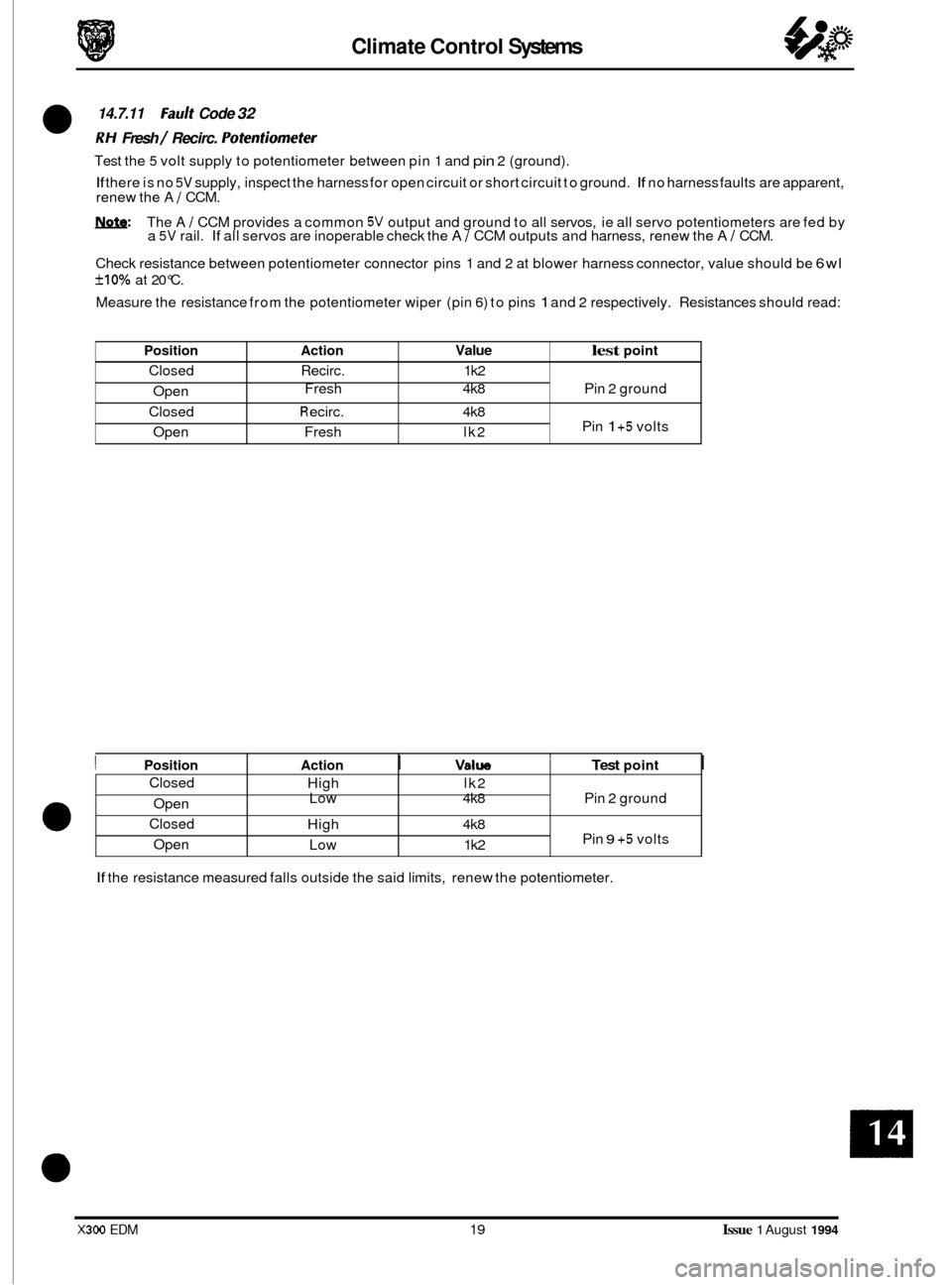
14.7.11 Fault Code 32
RH Fresh / Recirc. Pofenfiomefer
Test the 5 volt supply to potentiometer between pin 1 and pin 2 (ground).
If there is no 5V supply, inspect the harness for open circuit or short circuit to ground. If no harness faults are apparent,
renew the A 1 CCM.
W: The A / CCM provides a common 5V output and ground to all servos, ie all servo potentiometers are fed by
a 5V rail. If all servos are inoperable check the A 1 CCM outputs and harness, renew the A I CCM.
Check resistance between potentiometer connector pins 1 and 2 at blower harness connector, value should be
6wl
f10% at 20°C.
Measure the resistance from the potentiometer wiper (pin
6) to pins 1 and 2 respectively. Resistances should read:
Action Value lest point
Recirc. 1 k2
Fresh 4k8 Pin 2 ground
R eci rc. 4k8
Pin 1 +5 volts
Fresh lk2
Closed Open
Closed
Open
e
I Position I Action I Valw 1 Test point I
High lk2
Low 4k8 Pin 2 ground
High 4k8
Pin
9 +5 volts
Low 1 k2
If the resistance measured falls outside the said limits, renew the potentiometer.
X300 EDM 19 Issue 1 August 1994
Page 95 of 327

Climate Control Systems
Position
Closed
Open
Closed
ODen
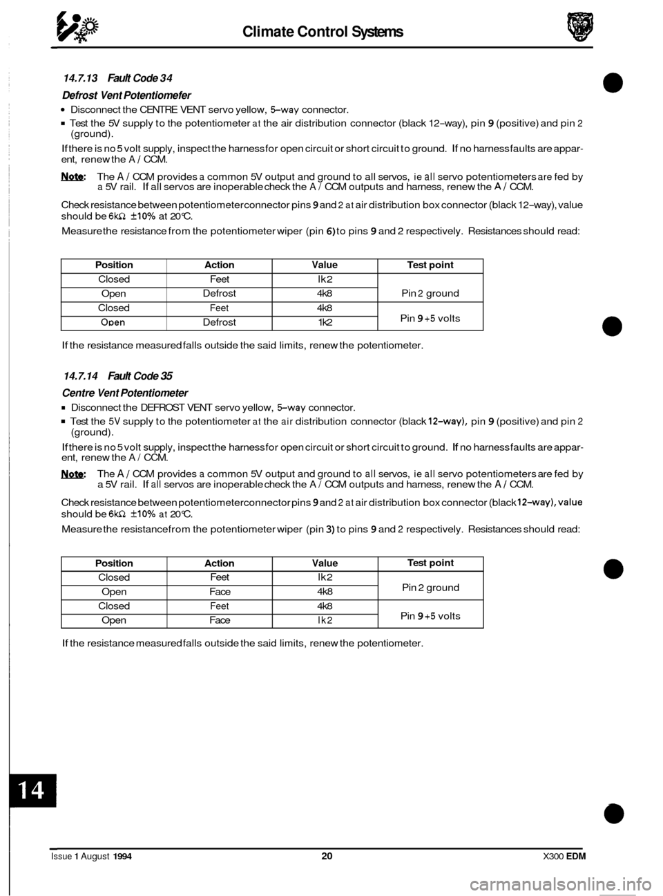
14.7.13 Fault Code 34
Defrost
Vent Potentiomefer
Disconnect the CENTRE VENT servo yellow, Sway connector.
Test the 5V supply to the potentiometer at the air distribution connector (black 12-way), pin 9 (positive) and pin 2
If there is no 5 volt supply, inspect the harness for open circuit or short circuit to ground. If no harness faults are appar-
ent, renew the A / CCM.
&&: The A / CCM provides a common 5V output and ground to all servos, ie all servo potentiometers are fed by a 5V rail. If all servos are inoperable check the A/ CCM outputs and harness, renew the AI CCM.
Check resistance between potentiometer connector pins
9 and 2 at air distribution box connector (black 12-way), value
should be
6w1 +10% at 20°C.
Measure the resistance from the potentiometer wiper (pin
6) to pins 9 and 2 respectively. Resistances should read:
(ground).
Action Value Test
point
Defrost 4k8 Pin 2 ground
Feet 4k8
Pin 9 +5 volts
Defrost 1 k2
Feet
lk2
Position Action Value
Closed Feet
lk2
4k8
Open Face
Closed
Feet 4k8
Open Face
lk2
If the resistance measured falls outside the said limits, renew the potentiometer.
Test point
Pin 2 ground
Pin
9 +5 volts
14.7.14 Fault Code 35
Centre Vent Potentiometer
Disconnect the DEFROST VENT servo yellow, Sway connector.
Test the 5V supply to the potentiometer at the air distribution connector (black 12-way), pin 9 (positive) and pin 2
If there is no 5 volt supply, inspect the harness for open circuit or short circuit to ground. If no harness faults are appar- ent, renew the A/ CCM.
The
A / CCM provides a common 5V output and ground to all servos, ie all servo potentiometers are fed by
a 5V rail. If all servos are inoperable check the A/ CCM outputs and harness, renew the A / CCM.
Check resistance between potentiometerconnector pins
9 and 2 at air distribution box connector (black 12-way),value
should be 6wZ +10% at 20°C.
Measure the resistance from the potentiometer wiper (pin
3) to pins 9 and 2 respectively. Resistances should read:
(ground).
If the
resistance measured falls outside the said limits, renew the potentiometer.
Issue 1 August 1994 20 X300 EDM
Page 96 of 327

Climate Control Systems
Position Action Value Test point
Closed Face 1 k2
Open Foot
4k8
Closed Face
4k8
Open Foot
1 k2
Pin 2 ground
Pin
9 +5 volts
14.7.15 Fault Code 36
Foot Vent
Potentiometer
Disconnect the COOL AIR BYPASS yellow, Sway connector.
. Test the 5V supply to the potentiometer at the main unit, pin 9 (positive) and pin 2 (ground).
If there is no 5 volt supply, inspect the harness for open circuit or short circuit to ground. If no harness faults are appar- ent, renew the A I CCM.
&&: The A I CCM provides a common 5V output and ground to all servos, ie all servo potentiometers are fed by a 5V rail. If all servos are inoperable check the A 1 CCM outputs and harness, renew the A 1 CCM.
Check resistance between potentiometer connector pins9 and
2 at blower motor connector, value should be 6kn +10%
at 20°C.
Measure the resistance from the potentiometer wiper (pin
6) to pins 9 and 2 respectively. Resistances should read:
14.7.16 Fault Code 4 1
1 H Fresh / Recirc. Motor
The resistance between pins 1 and 3, servo unit Sway connector, should read 4.8 - 7.2 kn.
If the resistance is outside of the set limits, renew the servo unit.
The motor operation can be checked by applying battery voltage to pin
5, motor %way connector, and ground to pin 4 of the connector. The motor arm should rotate smoothly in a clockwise direction. Renew the motor if the arm does
not rotate smoothly.
Apply battery voltage to pin
4, servo unit %ay connector, and ground to pin 5. The motor arm should rotate smoothly
in a anti-clockwise direction. Renew the motor if the arm does not rotate smoothly.
Inspect the harness for open circuit or short circuit to ground. Rectify as necessary.
If no harness faults are apparent,
renew the AI CCM.
14.7.17 Fault Code 42
RH Fresh / Recirc. Motor
The resistance between pins 1 and 3, servo unit Sway connector, should read 4.8 - 7.2 kn.
If the resistance is outside of the set limits, renew the servo unit.
The motor operation can be checked by applying battery voltage to pin
5, motor Sway connector, and ground to pin 4 of the connector. The motor arm should rotate smoothly in a clockwise direction. Renew the motor if the arm does
not rotate smoothly.
Apply battery voltage to pin
4, servo unit Sway connector, and ground to pin 5. The motor arm should rotate smoothly
in a anti-clockwise direction. Renew the motor if the arm does not rotate smoothly.
Inspect the harness for open circuit or short circuit to ground. Rectify as necessary.
If no harness faults are apparent,
renew the A I CCM.
21 Issue 1 August 1994