1994 JAGUAR XJ6 warning
[x] Cancel search: warningPage 8 of 327

Automatic Transmission (AJ16)
8.1.4 FA U1 T DIAGNOSIS
Transmission Control System Electrical - P 0702 (Fig. 1)
This fault code is associated with the internal relay of the Transmission Control Module, (TCM). This relay provides a
means of isolating the electro-mechanical, controlling, solenoids from the supply, allowing the transmission to revert
to a mechanical default condition.
The relay and associated circuitry is tested once during initialization and whenever
a hardware reset occurs. When the
ignition is first switched on the TCM carries out an initialization routine. During this routine the processor drives the
relay
ON then tests for the supply voltage on the output via a feedback path. If the supply voltage is not seen within
a specific time then
a fault is flagged and the TCM will run in default mode and this fault code will be stored.
A set time after the relay is turned on, it is turned off and the processor then tests for the supply again. If it is still present,
then the TCM will run in default mode and this fault code will be stored.
U: The ignition supply voltage must be greater than 8V for a fault code to be stored. If this fault is permanently
flagged, the TCM should be replaced taking care to obtain the correctly programmed variant.
Possible causes:
Faulty TCM internal relay.
Effects:
. MIL illuminated.
. Transmission warning lamp illuminated.
. Maximum fluid pressure applied.
Limp home mode applied.
. RenewTCM.
Remedy:
Fig. 1
X300 EDM 5 Issue 1 August 1994
Page 9 of 327

w Automatic Transmission (AJ16)
TRANSMISSION RANGE SENSOR - P 0705 / P 0706
The rotary switch is located on the LH side of the transmission. The harness incorporates the transmission wiring and
runs into the car through the a hole in the LH side of the tunnel. The connectors GBOOI and GB002 are located on the
side of the selector mechanism ‘J’ gate assembly.
TRANSMISSION RANGE SENSOR CIRCUIT - P 0705
This test is performed continuously by the background diagnostics during operation. The test is a plausibility check
on the 3 bit Gray code. The test criteria is that an invalid code must not be seen. If a Z code is seen for more than looms,
then this fault code will be stored and the transmission will adopt the default function.
TRANSMISSION RANGE SENSOR CIRCUIT RANGE/ PERFORMANCE - P 0706
This is a plausibilitycheck on the 3 bit Gray code which is only performed once during cranking when the engine speed
reaches
a specific threshold. If the gear is not P or N when this test is performed, then this fault code will be flagged
and the transmission will adopt the default function.
ROTARY SWITCH
(GB002)
PIN 1 -SWITCH COMMON
PIN
2 -CODE X OUTPUT
PIN
3 -CODE Y OUTPUT
PIN
4 -CODE Z OUTPUT
Possible causes
Open circuit on X, Y or Z line from rotary switch.
9 Faulty operation of rotary switch.
Effects:
. MIL illuminated.
. Transmission warning lamp illuminated.
. Maximum fluid pressure applied.
. Limp home mode applied.
Remedy:
. Repair or renew harness I connectors.
. Check selector cable and adjust or renew if necessary.
. Check rotary switch and adjust or renew if necessary.
X300 EDM Issue 1 August 1994 6
Page 13 of 327

Automatic Transmission (AJ16)
OUTPUT SPEED SENSOR - P 0721 / P 0722
The output speed sensor is located on the rear of thevalve block assembly inside the transmission. Connection is made
via pins A and F of the %way transmission connector located on the left hand side of the transmission assembly. The
wiring runs through the rotary switch harness and the vehicle gearbox harness to the TCM on pins 2 and 38 of the 55 way multi-plug. These wires are shielded by a screen which is terminated on pin 20 of the TCM multi-plug. The sensor
detects the motion of the output shaft via a 36 toothed wheel.
TCM ROTARY SWITCH TRANSMISSION
(CC007) (GB002) (GB003)
PIN 2 -SIGNAL PIN 11 -SIGNAL PIN F -SIGNAL
PIN 38
- GROUND PIN 12 -GROUND PIN
A - GROUND
OUTPUT SPEED SENSOR CIRCUIT RANGE/ PERFORMANCE - P 0721
This test is only performed when a downshift takes place and therefore the vehicle must be in a forward gear ie D, 3, 2, 1. A fault will be flagged if the engine speed is above a threshold which is dependant on the shift and the state of the lock up clutch.
This fault code would suggest that there is an intermittent fault in the circuit.
OUTPUT SPEED SENSOR CIRCUIT NO SIGNAL - P 0722
The background diagnostic software continuously monitors the output speed and flags this fault if the output speed
is zero when the engine speed is greater than 2000 rpm and a forward gear, D, 3,2,1, is selected.
This fault code would suggest
a permanent fault, either open circuit, short to ground or short circuit to battery positive
voltage (+12V nominal).
Possible causes:
Faulty sensor.
Faulty harness wiring I connectors.
Effects:
MIL illuminated.
Transmission warning lamp illuminated.
Maximum pressure applied.
Limp home mode applied.
Remedy:
Renew sensor.
Repair or renew harness I connectors. ~~~~ ~~
Issue 1 August 1994 10 X300 EDM
Page 15 of 327

w Automatic Transmission (AJ16)
ENGINE SPEED INPUT - P 0726 / P 0727
The engine speed input signal is a square wave output from the ECM. The signal is 12 volt active high with a duty cycle
of 50" / 120" of crankshaft revolution ie 3 pulses per revolution. The frequency of the signal is proportional to engine
speed.
TCM
PI HARNESS ECM
CC007/003 P1063/002 Pl104/022
ENGINE SPEED INPUT CIRCUIT - RANGE / PERFORMANCE P 0726
Engine speed is continuously monitored by the background diagnostics. This fault is flagged if the engine speed ex-
ceeds the maximum speed threshold (approx 6800 rpm). This fault code would suggest an intermittent fault in the cir- cuit.
ENGINE SPEED INPUT CIRCUIT NO SIGNAL - P 0727
If the engine speed drops below 95 rpm and the selected gear is not P or N, then the TCM will initiate the default mode.
This fault code will only be stored if the output speed is greater than 300 rpm. This is to prevent spurious flagging of
codes if the engine stalls.
Possible causes:
. Faulty harness wiring 1 connectors.
. Faulty signal from ECM.
Effects:
. MIL illuminated.
. Transmission warning lamp illuminated.
. Maximum fluid pressure applied.
. Limp home mode applied.
Remedy:
. Repair or renew harness /connectors.
. Examine ECM fault diagnosis (refer to EC Section 1).
Issue 1 August 1994 12 X300 EDM
Page 17 of 327

w Automatic Transmission (AJ16)
SOL ENOlD VALVES
The following tests are performed continuously by a background task. If a fault is detected, it is filtered for a set period.
When filtering ends a fault code is stored in the TCM and action is taken to ensure the integrity of the system.
During limp home mode the internal relay is turned
off to remove the supply to the solenoids and the gearbox with default to fourth gear (if aforward gear is alreadyselected) and third gear (if P.R.N.). Selecting N and then D will engage
3rd gear only.
Each test checks that the feedback from the output stage module is consistent
with the driven state of the solenoid
output, detects short circuit to ground, short circuit to battery voltage and open circuit.
TORQUE CONVERTER CLUTCH SYSTEM - P 0743
PRESSURE CONTROL SOLENOID ELECTRICAL
- P 0748
SHIFTSOLENOID A ELECTRICAL - P 0753
SHIH SOLENOID B ELECTRICAL - P 0758
TCM TRANSMISSION
ccoo7/042 G B003/L
CC007l005 GBOOYH
ccoo7/024 GB003lK
CC007/006 GB003/B
CC007/0 19 G B003/M
TORQUE CONVERTER CLUTCH
SHIFT SOLENOID
A
SHIFT SOLENOID B
PRESSURE CONTROL SOLENOID
SOLENOID SUPPLY
Possible Causes:
. Faulty valve.
Faulty harness wiring /connectors.
Effects:
MIL illuminated.
. Transmission warning lamp illuminated.
Maximum fluid pressure applied.
Limp home mode applied.
Remedy:
Renew valve.
. Repair or renew harness I connector.
Issue 1 August 1994 14 X300 EDM
Page 19 of 327

Automatic Transmission (AJ16)
TORQUE REDUCTION SIGNAL - P 1780
The diagnostic for this signal is based entirely on feedback from the ECM. If the torque reduction request is active for
greater than 2 seconds, the ECM starts the torque reduction fault timeout (IO seconds). If the signal returns to the
standby condition within this time, the timeout is reset. If the timeout matures then the ECM stores a fault code and
transmits 93% on the torque signal line and also lights the MIL where necessary.
The ECM will also initiate the torque reduction fault timeout
if the signal line is permanently high or low for greater
than 125ms. The conditions for resetting the timeout and the actions if the timeout matures are the same as previously
described above. When the TCM receives the correct indication on the torque signal line, this fault code will be stored
and
a substitute function will be adopted and the warning lamp will be illuminated. The engine management will send
normal torque signal when the torque reduction signal returns to standby or when the ignition is reset.
This torque reduction signal is used during gearshifts to conveythe actual amount of retard to be applied to the ignition
advance angle
afterthe other trims. The signal idles at 17% (or 12% if theTCM wishes to drive the MIL on), and changes
to 20% at the start of a gearshift. This represents 0" retard. When an amount of retard is required, the PWM will increase
to the desired value (between 20% and 90%) and return to 20% and then to idle state at the end of the shift.
TCM
PI HARNESS ECM
CC007/032 P1063/008 P1105/026
TORQUE SIGNAL MALFUNCTION - P 1781
The torque signal is a PWM signal from the ECM to the TCM which conveys information about the actual torque devel- oped by the engine in the range 0 to 510Nm. The base frequency is 91Hz and the signal which is active low should be
within the range 10% to 90% modulation. The torque signal is monitored continuously during initialization and oper
- ation. If the frequency of the signal is incorrect or the signal is out of range, then this fault code will be flagged. The
TCM will adopt a substitute function and the warning lamp will be illuminated. This fault code will only be flagged if the engine speed is above 448 rpm.
TCM
PI HARNESS ECM
CC007/02 1 P1063/007 PI 105/033
Possible causes:
. Faulty harness wiring I connector.
. Faulty signal from ECM.
Effects:
. Transmission warning lamp illuminated.
Substitute torque signal adopted by TCM.
. =Normal mode only available.
. No kickdown facility.
. Maximum fluid pressure applied.
Remedy:
. Repair or renew harness / connector.
Examine ECM fault diagnosis (refer to EDM, section 5.1).
Issue 1 August 1994 16 X300 EDM
Page 23 of 327

w Automatic Transmission (AJ16)
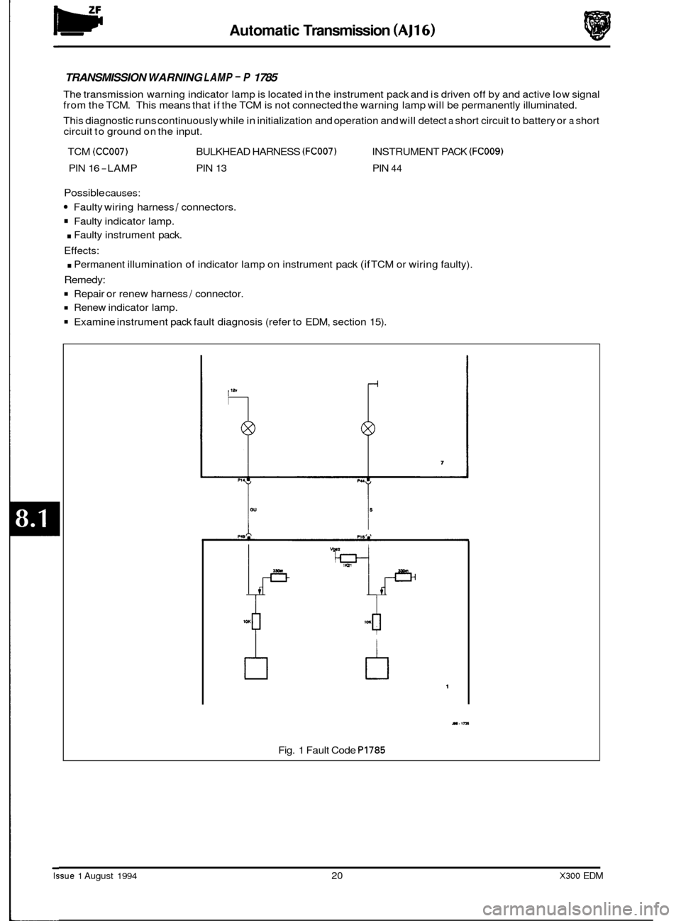
TRANSMISSION WARNING LAMP - P 1785
The transmission warning indicator lamp is located in the instrument pack and is driven off by and active low signal
from the TCM. This means that if the TCM is not connected the warning lamp will be permanently illuminated.
This diagnostic runs continuously while in initialization and operation and will detect
a short circuit to battery or a short
circuit to ground on the input.
TCM
(CC007) BULKHEAD HARNESS (FC007) INSTRUMENT PACK (FCOOS)
PIN 16 -LAMP PIN 13 PIN 44
Possible causes:
Faulty wiring harness / connectors.
Faulty indicator lamp.
. Faulty instrument pack.
Effects:
. Permanent illumination of indicator lamp on instrument pack (if TCM or wiring faulty).
Remedy:
Repair or renew harness / connector.
Renew indicator lamp.
Examine instrument pack fault diagnosis (refer to EDM, section 15).
/I
b
M(t I
4r^
tl 1
11.1rn
Fig. 1 Fault Code P1785
Issue 1 August 1994 20 X300 EDM
Page 24 of 327

Automatic Transmission (AJ16)
TP ELECTRICAL SIGNAL SYSTEM - P 1791
If the throttle angle signal line is held permanently high or low for more than looms, then this fault will be recognised
and stored. The TCM will adopt the substitute throttle value and turn on the warning lamp. The fault code will only be
stored if the engine speed is greater than 400rpm.
TCM PI HARNESS ECM
CC007/047 P1063/00 1 PI 1041032
Possible causes:
Faulty harness wiring I connection.
. Faulty ECM signal.
Effects:
Transmission warning lamp illuminated.
. MIL illuminated.
Normal mode only available.
Substitute throttle angle adopted.
No kickdown facility.
Remedy:
Repair or renew harness 1 connector.
Examine ECM fault diagnosis (refer to EDM, Section 5.1).
TP SIGNAL SYSTEM RANGE/ PERFORMANCE - P 1790
The throttle signal is a pulse width modulated (pwm) input which runs at a constant frequency of 183 Hz the information is contained in the duty cycle of the signal. If this information is out of range, that is, the duty cycle is less than 5% or
greater than 94%, then the TCM will use a substitute throttle value of 47% and will light the warning lamp and this fault code will be stored. During cranking, this signal is used to convey the engine coolant temperature. The coolant tem- perature signal persistsfor 500 msec after reaching the engine run threshold of 400 rpm. If theTCM does not recognise a valid throttle angle signal afterthis time then a substitute throttle value (47%) will be used and the warning lamp will
be
lit and this fault code will be stored. A fault code will only be stored if the engine speed is greater than 400 rpm. If an out of range coolant temperature is received then a substitute coolant temperature value (77" C) is used but no fault is stored.
X300 EDM 21 Issue 1 August 1994