Page 456 of 1413

Electrical Troubleshooting
Troubleshooting Flowchart (cont'dl
Possible Cau6e
. Disconnected shift control sole-noid valve B connector. Short or open in shift controlsolenoid valve B wire. Faulty shilt control solenoidvalve B
Solfdiagnolir [!4 Indicato. lightbllnk! eight tim6r.
Turn the ignition switch ON.
Check whother the MalfunctionIndicator Lamp {MlL) blinks (seesection I 11.
Rcpsir rho FGM-FI Syrtem lso6scciion l1l.ls the MIL blinking?
Turn the ignition swirch OFF.
Oisconn€ct the 26P and 22P con-nectors trom the TCM.Connect the Test Harness "A"
and "D" connectors to the wirohamess only. not to the TCM {sesp6ge 14-49).
Turn the ignition switch ON.
Measure the voltage betwe€n theD18 and A25 or A26 terminals.
Ropeir opon or short in WHT/BLKwiro trotweon th6 D18 termineland tho EcM.
ls the voltage 4.75-5.25 V?
Measure the voltage between th€A3 and A25 or A26 terminals.
Ropair rhort to powor rourco inGR /WHT wir6 b€twgan tho A3tormirEl and shift conLol lolonoidvalve B.
Turn the ignition switch OFF.
A2s( - |
DlA( + I
o oooooooooo
ooooooooooooo oo ooo ooooo
oooo o o oo
To page
Page 460 of 1413
Electrical Troubleshooting
Troubleshooting Flowchart (cont'dl
Possibl€ Caus6
. Disconnoct€d engine coolantt€mp€rature (ECTI sensor con-noctor. Short or open in the ECT sensor
. Faulty ECT s€nsor
Self-diagnosis E indicator lightblinks ten times.
Turn the ignition switch ON.
Check whether the MalfunctionIndicator Lamp {MlL} blinks (seesection 1 1)-
ls the MIL blinking?Rop.ir tho PGM-FI Syrt.m (!go
!.ction 111.
Turn the ignition switch OFF.
Disconnectthe 26P and 22P con-nectors trom the TCM.Connect the Test Harness "A"
and "D" conneclors to the wireharness only, not to the TCM (seepage 14 49).
Measure the voltage between theD'18 and A25 or A26 lorminals.
Bopair op.n or .hofi In WHT/BLKwiro botwoon tho O18 tanni.|al.nd the ECM.ls the voltage 4.75-5.25 V?
Turn the ignition switch OFF.
oooooooooooo
ooooooooooooooooooooooo
oooo o oo o
Dlal + I
Page 462 of 1413
Electrical Troubleshooting
Troubleshooting Flowchart (cont'd)
Possible Cause
. Disconnected ignition coil con-neclor. Short or open in ignition coil
. Faulty ignition coil
Solt-diagnosis lq.l indicstor lightblinks elovon tim6s.
Disconnect the 26P connectorIrom the TCM.
Turn the ignition switch ON.
Measure the voltage between theAg (BLU) and A25 (BRNiBLK) orA26 (BRN/BLK) terminals.
ls there baftery voltage?R6pai? opon or short in BLU wirolrotwqan lh. A9 torminll 6nd th.ignilion c!il.
Ch6ck lor loos6 TCM connactora.It nacosaary, substituto a known-good TCM and rochock.
NOTE: View from wire side.
14-70
Page 463 of 1413

Disconnect lhe 26Pand 22P con-nectors trom the TCMConnect the Test Hahess "A"
and "D" connectors to the wireharness only, not to th€ TCM {seepare'14-49).
Possible Cause
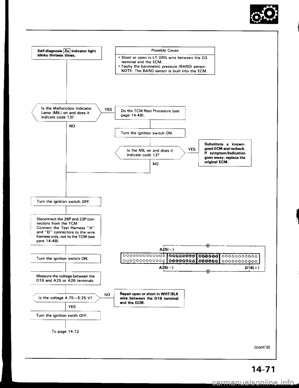
. Short or open in LT GRN wire between the D3terminal and the ECM.. Fauky the barometric pressure {8ARO} sensor.NOTE: The BARO sensor is built into lhe ECM.
ooooooooooooo
oooooooooooo0oOOqgopg I,oiOOOOol ooo ooooooooooocqooo:Joo.oipggl o oooooo o 9ooTurn the ignition swirch ON.
Measure the voltage between theD18 and A25 or A26 terminals.
ls the voltage 4.75-5.25 V?
Turn the ignition swith OFF.
A25t- |
Soll-diagnosis Lq! indicator lightblinks thirtoon tim6.
ls rhe Malfunction lndicatorLamp (MlL) on and does itindicate code 13?
Do the TCM Rest Procedure (seepage 14-49).
Turn the ignition switch ON.
Substituto a known-good ECM and rechock.ll symptom/lndicationgoos away, .oplace theoriginal ECM.
ls the MIL on and does itindicare code 13?
Turn the ignition switch OFF.
Ropair opon or short in WHT/BLKwir6 botwoon th€ D18 to.minaland tho EcM.
fo page 14-72
14-71
Page 465 of 1413
S.fdl.enorl! L&l indicdor lighlblinks fourtoon tlmoa.
ls the Malfunction IndicatorLamp (MlL) onl
Stan the ongine and warm it upto normal operating temperature{th€ radiator lan com€s on).
Shift to E position,
Turn rhe ignition switch OFF.
Possible Cause
. Sh"rt ". "e"" i" FAS |YEU ,"rirt. Fsulty ECM.
Connect the Test Harness be-tween the TCM and connociors{see page 14-491.
Turn the ignition switch ON andwsit for at least two seconds.
o oooooo ooo ooo l.tto.oodooo l:,gEoo.ottl o ooooo oooo o
o oooo oooooooo l:OOOO OO 60 l.,OO{tO.O6,'l o oooooooooo
Measure lhe voltage betwgan thso16l+ ) and A25 or A26(- | tor-mrnals.
lcont'd)
Ropair tho PGM-FI Syrtom lloo..ctlon 111.
Chock for looro TCM connoctora.lf noco$ary, subatituta a known-good TCM and .ech€ck.ls thoro approx. 5 V?
Turn the ignition switch OFF.
Dkconnect the Test Harness fromthe TcM.Leave connect€d to car harness.
Turn the ignition switch ON.
fo page 14-74
14-73
Page 469 of 1413
@ indic"to, light i8 on st6sdyInot blinkingl whenevor the ioni-tion switch is ON.
Disconnect the 26P connectorfrom the TCM.Connect the Test Harness "A"
connector to the wite harnessonly, not to the TCM (see page14-49).
Turn the ignition switch ON.
Measure the voltage between theA8 terminal and body ground.
Ropair shon to power in GRN/BLKwiro botwoen A8 terminal andgauge assembly.
Check for a sho.t to ground on thePNK/GRN wi.e. ll th€ wir. is OK,roplac€ the A/T gear poaition in-dicator.
Turn the ignition switch OFF.
ls there voltage?
Connect the Test Harness "A"
conneclor to the TCM.
Measure the voltage between the417 terminal and body groundwith the selector lever in anv oo'sition other than El.
ls there volrage?
ReDlace tho TCM.
o o o o oo o oo o oo o l:qssoo9pc,I:oocto:osil o o o oo o o o o oooooQoooooooooo oo o oooo ooo
{cont'd)
14-77
Page 470 of 1413

Electrical Troubleshooting
Troubleshooting Flowchaft (cont'dl
Does the @ indicatorcome on?
ls there baftery voltage?
YES
lighr
I A25
| | o ooooo o oo o ooo r:sjc.o.sl'1*st,li*os.s.4tcl ooo oo oooooo I
I I o o o o o o o o o o o o q lifrif.S..n${5git:li$gg-:aiiigitll o o o o o o o o o o o I|--.-T..-I a26
+d
+
I + )A23 A25l - l
(+ tA24 426(- |t\@
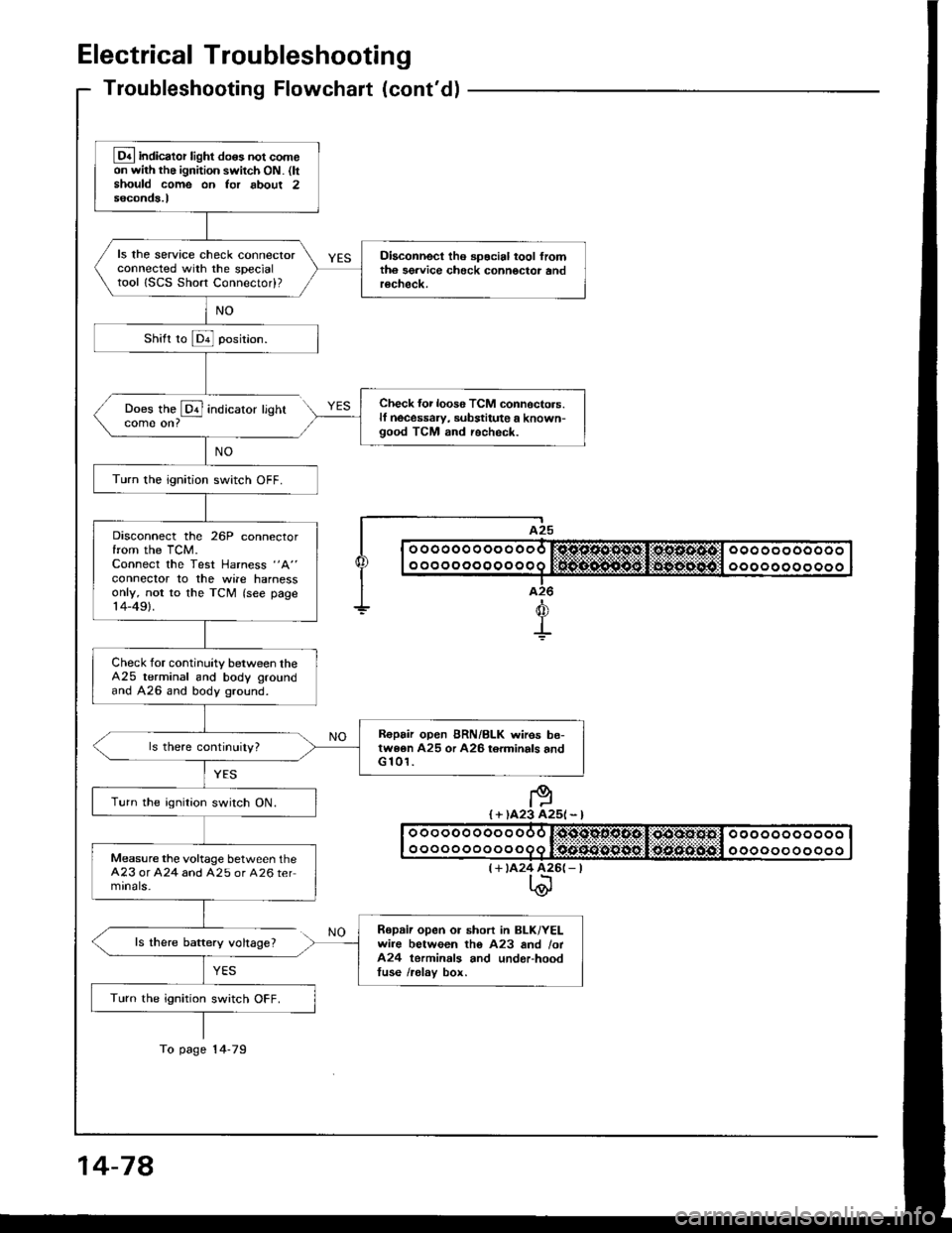
Lq4 indicator light do6s not comeon with the ignition switch ON. (ltshould come on Ior about 2seconds.l
ls the service check connectorconnected with the specialtool ISCS Short Connectod?
Diaconnect tho spocial tool fromth6 sgrvice check connoctor andrecheck.
Check {or loos6 TCM connoctors.lf necessaw, substitute a known-good TCM and recheck.
Turn the ignition switch OFF.
Disconnect the 26P connectorfrom the TCM.Connect the Test Harness "A"
conneclor to the wile harnessonly, not to the TCM (see page14-49).
Check for continuity between theA25 terminal and body groundand A26 and body ground.
R€pair open BRN/BLK wires be-twe6n A25 or A26 torminals andG 101.
Turn the ignition switch ON.
Measure the voltage between theA23 or A24 and A25 or A26 termrnals-
Repaii open or short in BLK/YELwire between tho A23 and /ot424 terminals and underhoodtuse /relav box.
Turn the ignition switch OFF.
To page 14-79
14-78
Page 471 of 1413
Connect the Test Harness "A"
connector to the TCM.
Turn the ignition switch ON.8e sure that voltage is availablefor 2 seconds between thg A8 tor-minal and A25 or A26 terminal.
Chrck for opon or rhort in GR /8LK wirc bctw.on th. A8 termi-nal and tha gauOa arrambly.
Turn the ignition switch OFF.
Disconnect the Test Harness "A"
connector from the TCM.
Check for continuity between theA8 terminal and the GRN/BLKwire at tho gaugo assgmbly (see
section 23).
B.p.ir op.n in GRI{/BLK wi.. bo-lwaen the A8 terminal and th.gauga 6aaombly.
Ch€ck for loor6 TCM conn6ctor3.Check the A/T goa. polition
awitch. ll noc€$ary, subrtitutg aknown-good TCM .nd rochock.
ooooooooooo
ooooooooooo
oooooooooooo
oooooooooooo
a26t - |
A8(+)
(cont'd)
14-79