Page 1182 of 1413

Starting System
Startel Test
NOTE: The air temDerature must be between 59 8nd
10OoF (15 and 38oC) before testing.
Recommendsd Procodure:
a Use a staner svstem tester.
a Connect and operate the equipment in accordance
with the manutacturer's instructions.
a Test and troubleshoot as described.
Altohato Procedure:
a Use the following equipment:- Ammeter. 0-4OO A- Voltmeter, O- 20 V {accurate within 0.1 volt)
- Tachometer, O- 120O rpm
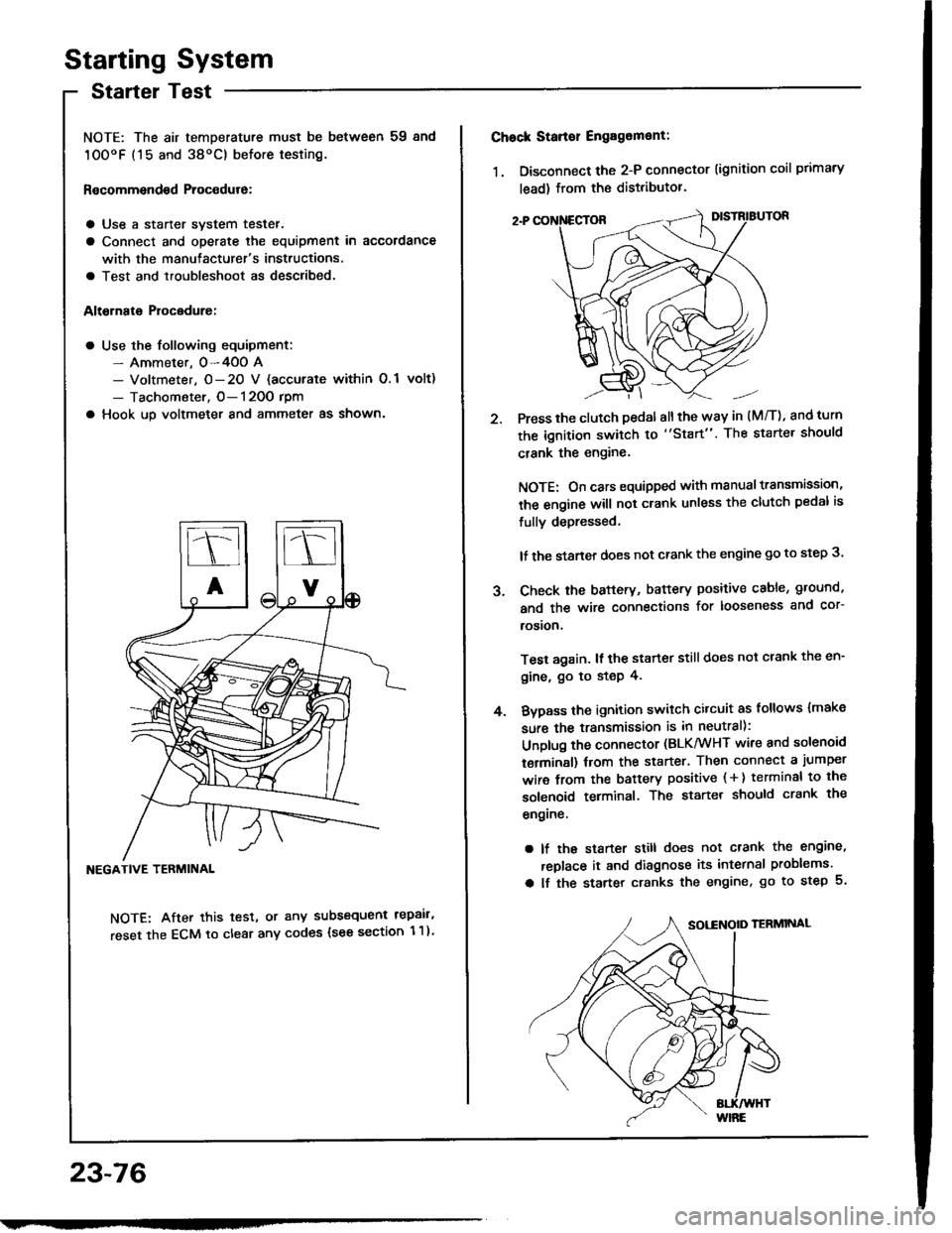
a Hook up voltmeter and ammeter as shown'
NEGATIVE TERMINAL
NOTE: After this test, or any subsequent repair,
reset the ECM to clear any codes (see section 1 1)
23-76
2.
Chock Stan€r Engag6ment:
1. Disconnect the 2-P connector (ignition coil primary
lead) from the distributor.
Press the clutch pedal allthe way in (M/T), and turn
the ignition switch to "Start". The starter should
crank the engine.
NOTE: On cars equipped with manual transmission,
the engine will not crank unless the clutch pedal is
fully depressed.
lf the staner does not crank the engine go to step 3.
Check the baftery, battery positive cable, ground,
and the wire connections for looseness and cor-
rosion,
Test again. lf the starter still does not crank the en-
gine, go to step 4.
Bvpass the ignition switch citcuit as follows {make
sure the transmission is in neutral):
Unplug the connector (BLK/WHT wire and solenoid
terminsl) trom the starter. Then connect a jumper
wire from the battery positive ( + ) terminal to the
solenoid terminal. The starter should crank the
engrne.
a lf the starter still does not crank the engine,
replace it and diagnose its internal problems.
a lf the starter cranks the engine, go to step 5.
J.
4.
Page 1183 of 1413

5. Check lor 8n op€n in the BLKMHT wire circuit be-
tween the staner and ignition switch, and con-
nectors.
6. Check the ignition switch (see page 23-70).
7, On cars with automatic transmission, check the A/Tgear position switch (neutral position switchl and
connector. On cars with manualtransmission, check
the staner cut relay, clutch interlock switch, and
connectors.
NOTE: Check the No. 39 (5O A) fuse in the under-hood
fuse/relay box for the starter cut relay.
Check tor Woar and Damago:
The starter should crank the engine smoothly and stead-
ily. lf th€ startsr engages, but cranks the engine errati-
cally, remove it. Inspect the starter, drive gear, and
flywheel ring gesr for damage.
a Check the drive gear overunning clutch for binding
or slipping when the armature is rotated with the drivegear held. Replace the gesrs if damaged.
Check Cranking Voltago 8nd Current Draw:
Cranking voltage should be no less than 8.O volts.
Current draw should be no more than 360 amperes.
lf cranking voltag€ is too low, or current draw too high,
check for:
a Fully charged battery
a Open circuit in starter armature commutatot segments
a Starter armature dragging
a Shoned armature winding
a Excessive drag in engine
Chack Cranking rpm:
Engine spsod during cranking should be above 1O0 rpm.
lf spe6d is too low, ch€ck for:
a Loose battsry or starter teminals
a Excessively worn starter brushes
a Open circuit in commutator segments
a Dirty or damaged helical spline or drive gear
a Defective drive gear overrunning clutch
Chock StErtor Disongagomoni:
Press the clutch pedal allth€ way in (M/T), turn the ioni-
tion switch to "lll" and rolease to "11".
The starter drive gear should disengage from the tlywheel
ring gear. When you rolease the key.
lf the drive gear hangs up on th€ flywheel ring gear, check
for:
a Solenoid plunger and switch malfunction
a Dirty drive gear assembly or damaged overrunning
clutch
23-77
Page 1193 of 1413
lgnition System
Gomponent Location Index
IGNITION TIMING CONTROL SYSTEMa Troubleshooting, section I1a Inspection and setting, page 23-89
DISTRIBUTORTop End Inspection, page 23-91Removal/lnstallation, pages 23-91, 92Overhaul, page 23-93Reassemblv, page 23,94lgnition Coil Test/Replacement, page 23-95lgnition Control Module {lCM} Inpur Test, page 23-96
WIRESInspection, psge 23-94
SPARK PLUGSfnspection, Page 23-97
23-87
Page 1195 of 1413
lgnition Timing Inspection and Setting
1.Start the engine. Hold the engine at 3,00O rpm with
no load (A/T in S or E position, M/T in neutral) until
the radiator fan comes on, then let it idle.
Pull out the service check connector located behind
the right kick panel. Connect the BRN/WHT and BLK
terminals with the SCS short connector.
4. Adiust ignition timing, if necessary, to the follow-
ing specifications:
lgnition Timing:
16 t 2 BTDC (RED) at 75O 1 50 rpm in noutral
NOTE:
a Shift lever must be in neutral.
a All electrical systems should be turned OFF.DATA LINKCONNECTOR {3-P}NOTE: Do not attachthe jumper wire.
POINTER
SCS SHORT CONNECTOR{0?PAZ-O010't 00t
SERVICE CHECK CONNECTOR I2.PINOTE: Located behind the right kickoanel
Connect a timing light to the No.1 ignition wire andpoint it toward the pointer on the timing belt cover.
TIMING LIGHT
lcont'd)
REO MARK
23-89
Page 1196 of 1413
lgnition System
lgnition Timing lnspection and
Setting (cont'd)
5. To adjust ignition timing, loosen the distributor
mounting bolts, and turn the distributor housing
counterclockwise to advance the timing, or clock-
wise to retard the timing.
MOUNN G BOLTS24 N.m (2.4 kgl.m, 17 lbt'ftl
Tighten the adjusting bolts and recheck the timing.
Remove the SCS short connector trom the service
check connector.
2.
ldle Speed Inspection
Shift to neutral or Ll] and start the engine. Hold the
engine at 3,OOO rpm with no load until the radiator
fan comes on, then let it idle.
Connect a tachometer to the test tachometer con-
nector.
ldle sp6od
M/T: 750 t 50 rpm in neuttal
A/T: 75O t 50 rpm in @ or @
NOTE: Allelectrical systems should be turned OFF.
Adjust the idle speed il necessary (see section 1 1).
b.
23-90
Page 1197 of 1413
Distributor Top End Inspection
1.
2.
Check for rough or pitted rotor and cap tefminals.
Scrape or file oft the carbon deposits.
Smooth the rotor terminal with an oil stone or #600sandpaper i{ rough.
Check the distributor cap Jor cracks, wear, and
dSmage, lf necessary, clean or replace it.
2
Distributor Removal
1.
2.
Disconnect the 2-P and 8-P connectors from the dis-
tributor.
Disconnect the ignition wires from the distributor
cap.
3. Remove the distributor mounting bolts, then remove
the distributor Irom the cvlinder head.
23-91
Page 1198 of 1413
lgnition System
Distributor Installation
Coat a new O-ring with engine oil, then install it.
Slip the distributor into position.
NOTE: The lugs on the end of the distributor and
its mating grooves in the camshaft end are both off-
set to eliminate the possibility ot installing the dis-
tributor 18Oo out of time.
DISTRIBUTOR END CAMSHAFT END
Install the mounting bolts and tighten them tem-
porarily.
Connect the 2-P and 8-P connectors to the dis-
tributor.
24 N.m (2.4 kgf'm' 17 lbt'ft|
23-92
5. Connect the ignition wires as shown.
Set the timing with a timing light (se€ page 23-89).
After setting the timing, tighten the mounting bolts.
Page 1199 of 1413
Distributor Overhaul
Check for cracksoa damage.
ROTOR RETAII{IITG SCREWlMust be made ofdiamagnstic materiall
DlsTNIBUTOR
Chock tor cracks, wear, damage,or fouling.Clean or replace.
IGNITION CONTROL MODULE {ICM)Troubleshooting, section 1 1Input tost, page 23-96
BLKTYEL
HOUSING
23-93