Page 1200 of 1413
lgnition System
Distributor Reassembly
23-94
1.When reassembling the dislributor, install the distri-
butor rotor so on the shaft that it faces in the direc-
tion shown (toward the No. 1 cylindetl,
2.Align the index mark on the distributor housing with
the index mark on the end of the shaft.
INDEX MARKS
lgnition Wire lnspection and Test
CAUTION: Caretully removo the ignition wiros by pull-
ing on tho rubbq boots. Do not bend the wilos; you might
bl€ak tham inside.
1 . Check the condition of the wire terminals. lf any te.-
minal is corroded, clean it. and if it is broken or dis-
torted. reolace the wire.
IGNITION WIRE
Connect ohmmeter probes and measure resistance.
lgnition Wile Roaistanco:
25 k0 max. at 68oF (2OoCl
2.
IGNITION WIRE
3. lf resistance exceeds 25 kO, replace the ignition wire,
Page 1201 of 1413
lgnition Coil Test
With the ignition switch OFF, remove the distribu-
lor cap.
Remove the two screws to disconnect the BLK^/EL
and WHT/BLU wires from terminals A (+ ) and B ( - )respectively.
3. Using an ohmmetet, measur€ tesistance betwe€nthe terminals, Replace the coil if the resistance is notwithin specifications.
NOTE: Resistance will vary with th€ coil t€m9er-ature; sp€cifications are at 68oF l20oC)
Prlmary Winding Rosistanco(8otwo6n tho A and B torminalsl: 0.6-0.g ohmsSecondary Winding Rssistanc6(Botwoon the A and socondary winding tomlnalsl:12.8 - 19.2 kO
lgnition Coil Replacement
1 . With the ignition switch OFF, remove the disrribu-
tor cap, rotor, and cap seal, then remove the leak
cover.
Remove the two screws to disconnect the BLK/YEL
and WHT/BLU wires from the coil.
Remove the two screws and slide the ignition coil
out of the distributor housing,
CAP SEAL
3.
A l+)
I
t
l
11
L
WHT/BLU WIRE
B {-}
23-95
Page 1202 of 1413

lgnition
lgnition
System
Control Module (lCMl Input Test
NOTE:
a See section I 1 if the malfunction indicator lamD (MlL)
blinks.
a Pertorm an input test for the ignition control module
(lCM) after finishing the fundamental tests for the ig-
nition system and the fuel and emissions systems.
a The tachometer should operate normally.
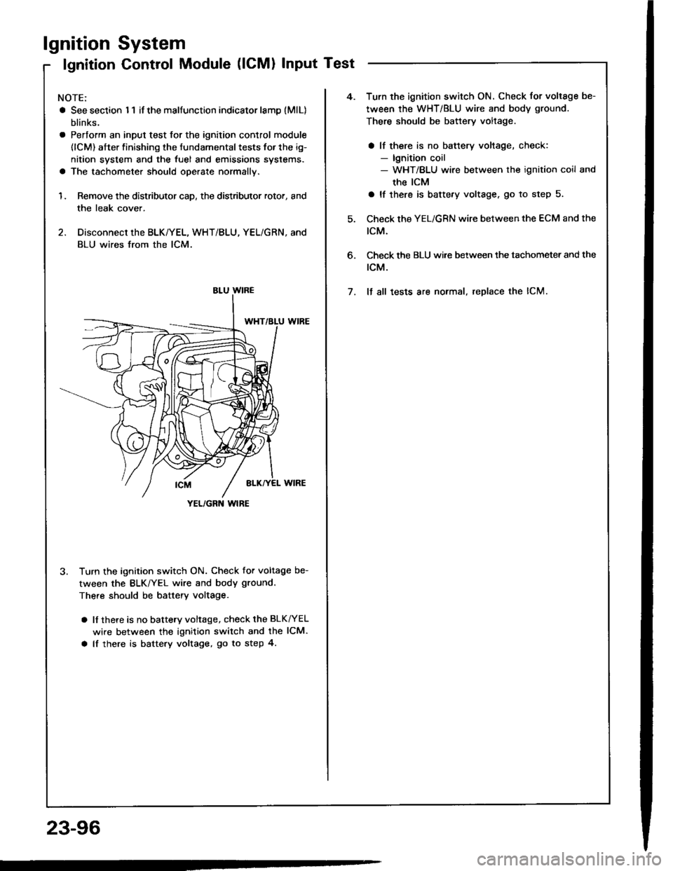
1. Remove the distributor cap, the distributor rotor, and
the leak cover.
2. Disconnect the BLK/YEL, WHT/BLU, YEL/GRN, and
BLU wires from the lCM.
3. Turn the ignition switch ON. Check for voltage be-
tween the BLK/YEL wire and body ground.
There should be battery voltage.
a lf there is no battery voltage, check the BLK^/EL
wire between the ignition switch and the lCM.
a lf there is battery voltage, go to step 4.
YEL/GRN wlRE
4.Turn the ignition switch ON. Check for voltage be-
tween the WHT/BLU wire and body ground.
There should be battery voltage.
a lf there is no battery voltage, check:- lgnition coil- WHT/BLU wire between the ignition coil and
the ICM
a lf there is battery voltage. go to step 5.
Check the YEL/GRN wire between the ECM and the
tcM.
Check the BLU wi.e between the tachometer and the
rcM.
It all tests are normal, replace the lCM.
6.
7.
23-96
Page 1203 of 1413

Spark Plug Inspection
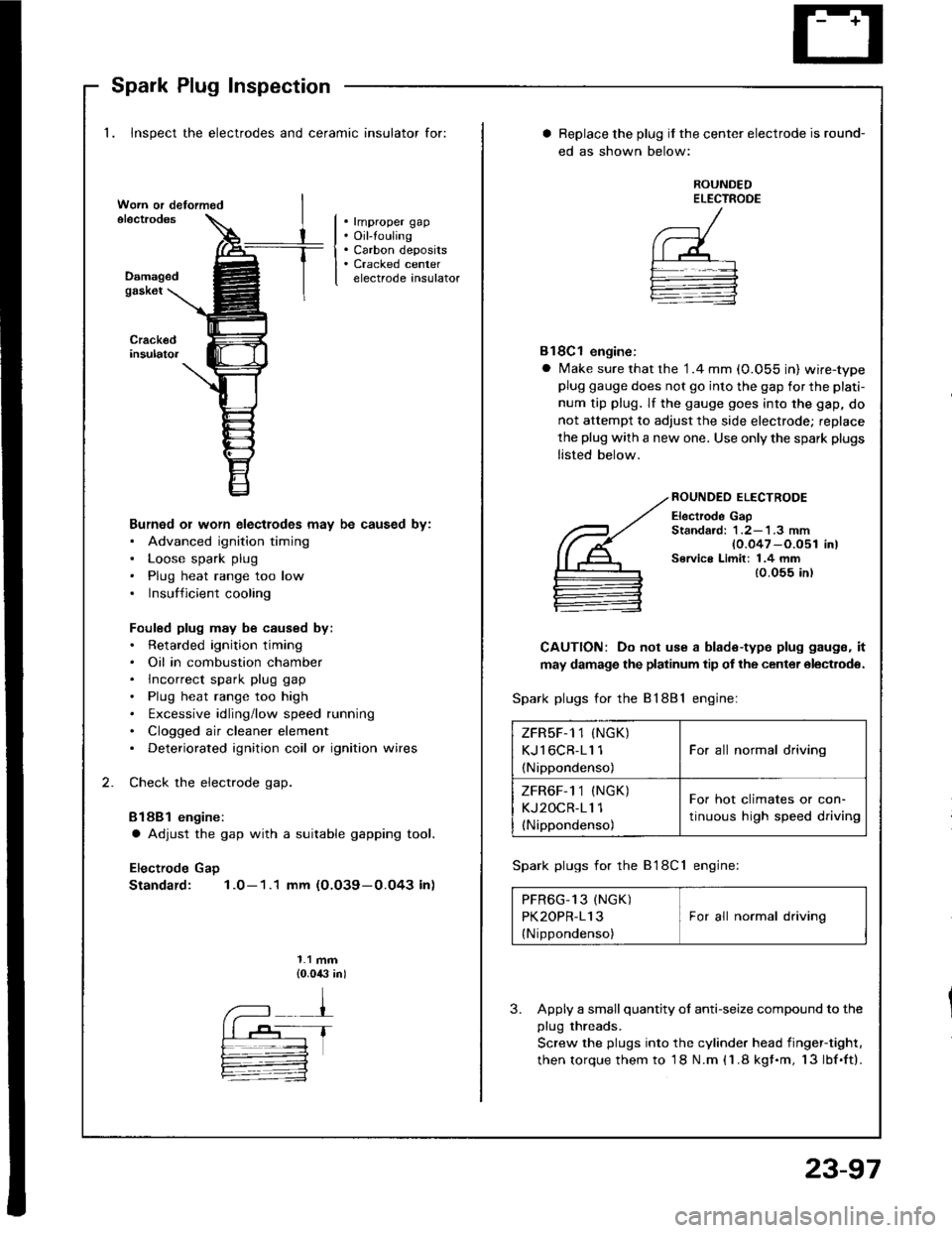
1. Inspect the electrodes and ceramic insulator for:
. rmproper gap. Oil-touling. Carbon deposits. Cracked centerelectrode insulatorDamagedgask6t
Burned or worn electlodes may be caused by:. Advanced ignition timing. Loose spark plug. Plug heat range too low. Insufficient cooling
Fouled plug may be caused by:. Retarded ignition timing. Oil in combustion chamber. lncorrect spark plug gap. Plug heat range too high. txcessive idling/low speed running. Clogged air cleaner element. Deteriorated ignition coil or ignition wires
Check the electrode gap.
Bl88l engine:
a Adjust the gap with a suitable gapping tool.
Electrode Gap
Standard: 1.0-1.1 mm (O.O39-0.O43 in)
1.1 mm{0.0,$ in)
Replace the plug if the center electrode is round-
ed as shown below:
ROUNDEDELECTROOE
Bl8Cl engine:
a Make sure that the '1.4 mm (0.055 in) wire-typeplug gauge does not go into the gap for the plati-
num tip plug. lf the gauge goes into the gap, do
not attempt to adjust the side electrode; replace
the plug with a new one. Use only the spark plugs
listed below.
ROUNDEO ELECTRODE
Electrode GapStandard: 1 .2-'l .3 mm{0.047 -O.051 in)Service Limit: 1.4 mm{0.055 in)
CAUTION: Do not use a blade-type plug gaugs, it
may damage the platinum tip of the center olectrodo.
Spark plugs for the 81881 engine:
Spark plugs for the B'l8Cl engine:
PFR6G_13 (NGK) IPK2OPR-113 I For all normal driving
{Nippondenso)
3. Apply a small quantity ol anti-seize compound to the
plug threads.
Screw the plugs into the cylinder head iingef-tight,
then torque them to 18 N.m (1.8 kgf.m, 13lbf.ft).
ZFRsF-1 1 (NGK)
KJl6CR-11 1
(Nippondenso)
For all normal driving
ZFR6F-1 1 (NGK)
KJ2OCR-11 1(Nippondenso)
For hot climates or con-
tinuous high speed driving
23-97
Page 1206 of 1413

Charging System
Troubleshooting
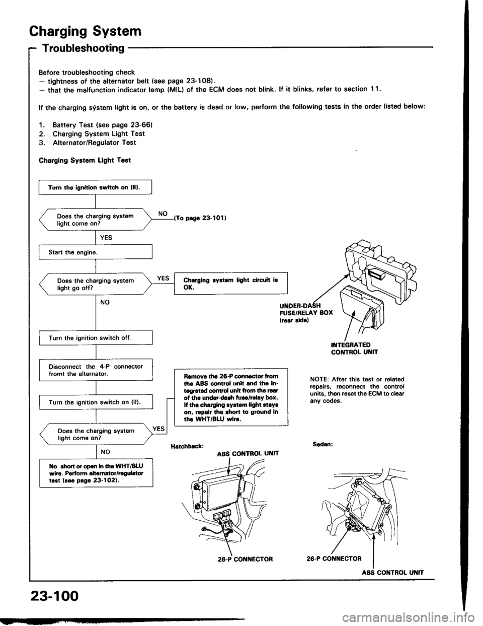
Bofore troubleshooting check- tightness of the alternator belt (see page 23-1Og).- that the malfunction indicator tamp lMlL) of the ECM does not blink. lf it blinks, refer to section 1 1.
lf the charging system light is on, or th€ battery is dead or low, p€rtorm the following tests in the order listed below:
1. Baftery Test (see page 23-66)
2. Charging System Light Test
3. Alternator/RegulatorTest
ChErging Sysrom Light T6tt
o pago 23-1011
FUSE/RELAY BOX(r..r tid.)
I'{TEGRATEDCO]TTROL UI{IT
NOTE: After this test or relaledrep6irs, roconnoct the controlunits. th6n aoset th€ ECM to cloarany cooos.
H.tchb.ck:Sad.n:
ABS COI{TROL UNIT
2A-P CONi{ECTOR
23-100
Tu]n tho ignhlon srvitch on (lll.
Does th€ charging syslemlight come on7
Does tho charging systemlight go ott?
Turn the ignition switch otf.
Disconnect the 4-P connoctorlromt th€ altornator.Ramova tfto 26-P connactd tromth. ABS control unh snd lh. in-tggrotad conrol unh ttoln tha tadol tho und..dlrh tu!a/r.l.y box.It thr .hlrglng .yrtom lighl .l.Y.on, rrpalr tho ahon to ground Inrhr WHT/BLU wi...
Turn the ignition switch on {ll),
Does the charging systemlight come on?
tlo rhon o. opon h ih. WIfT/BLUwho. Porfom dtomrtor/rogdttolrost beo pag. 23-l02l.
26.P CON ECTOR
ABS CONTROL
Page 1207 of 1413
lFrom page 23-10O)'No. 24 (15 A): 818B'lNo. 24 (20 A): 818C1ongrneengine
Turn the ignition switch ott.
Check fuse *No. 24 in the under-dash tuse/relay bor.
Disconnect the 4-P connectorIrom the alternator.
Turn the ignition switch on {ll).
Ch6ck forvoltago between tho lGterminal (BLK/YEL wire) of rho il-Pconnector and body ground.
ls there battery voltage?Rgp.i. op.n in th. BLK|'EL wiro.
Ground the WHT/BLU wire at theL terminal ot the 4-P connector.
Chock for ! blown chrrging ry3-rom llghr bulb. It rh. butb i! oK,ropair open in lho IiYHT/BLU wiro.
Does the charging system lightcome on?
wirg sideL IWHT/BLUI
(cont'd)
23-101
Page 1209 of 1413
(From page 23-1021
Apply a load wirh the VA'-4O un-til the battery voltage drops to be-tween 12- 13.5 V.
ls the amperage 60 A or more?
With the engine spe6d still at2OOO rpm, full-tield the altemalor.
Toat rnd rooalr d|e dtomEtor {soopsg.. 23-104 to 23-tO7).
Turn the ignition switch off; thenturn at on again.
Disconnocl lhe 4-P connectorIrom the altornator.
Check lor voltage between the lGterminal (BLK/YEL) and bodyground.
ls there battery vokage?Rop.ii open in tho BLK/YEL wiro.
NOTE; Attach a probe to the VAT-4O full field test lead and insert the orobeinto the full tield sccess hole at the back of the alternator. Switch the field selectorto the "A (Ground)" position momentarily and check amperage reading.
CAUTION: The voltago will ris6 quickly whon the slternator is full-fiolded. Donot allow th€ voltago to oxc66d 18 V 01 it may damage the elect.ical system
REGULATOR
{Locatodthe end cover)
FULL FIELDACCESS HOLE
L IWHT/BLUI
4-P CONNECTOR
IG IBLKATELI
wire side
23-103
Page 1220 of 1413
Gauge Assembly
Gauge/lndicator/Terminal Location Index
CAUTIOI{:
a All SRS olectrical wiring harnessos aro covorod with
yellow insulation,
Belol€ disconnecting any part ot tho SRS wiro hat-
nesa. connoct the short connoctol(El.
Replaco th6 entire aff6cted SRS hamess sssombly lf
it has an open circuil or damagod widng.
co r{EcroR "c" (c558}
FUEL GAUGE:Gauge Test, page 23-123
Sending Unit Tost, page 23-124
23,-114
A/T GEAR POSIT|OIIDICATOR SYSTEISee pags 23-132
E GI[{E COOLAI{T TEIIPEFATURE IECTIc6uge TEst, p6g6 23-126Sending Unit Tsst, pago 23-126
TACHOMETER:Indicatos lOO rpm at20O puls€s per minul€of the ignition controlmodul€ llCM).
SPEEDOMETER:Indicates (60 mph 6i 1025 rpml or{60 km/h at 637 rem) of th€v€hicle spe6d sonsor lVSSl.
CoNNECTOR "8" (c5601
Bi ----------+ B16Cl ----+ClO
f',. /i)
)Y
-"b
\_./ \J \-___--
a1 -----> A5
Dl-------.>D13
col{]{ECTOR "D" (C5591
rtrF --
coNNECfOR "A" (C557)