Page 1398 of 1413
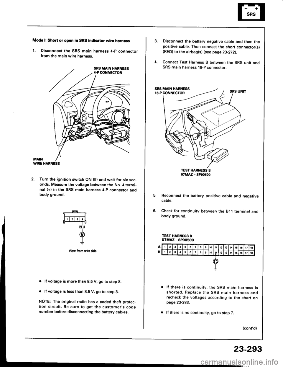
Modc l: Short 01 opcn in SRS indicrtor whc hrrnaas
1. Disconnect tho SRS main harness 4-p connectorfrom the main wirs harn6ss.
WIRE HABNESS
2. Turn the ignition switch ON (ll) 8nd wait for six sec-onds. Measu.s the voltage between ths No. il termi-nal (+) in the SFS main harness 4-P connector andbody ground,
. lf voltage is more thsn 8.5 V, go to step 8.
. It voltage is less than 8.5 V, go to step 3.
NOTE: The original radio has a coded theft protec-
tion circuit. Be sure to get the customer's codenumber before disconnecting the banery cables.
*-
F4
BLU
d.L
Vrow llom wi|! rftro.
Disconnect the battery negative cable and then thepositive cable. Then connect the sho.t connector(s)(REDlto the airbag(s) (see page 23-272).
Connect Test Harness B between the SRS unit andSRS main harness 18-P connector.
5. Reconnect the battery positive cable and negativecaote.
6, Check for continuity between the 811 terminalbody ground.
lf there is continuity, the SRS main harness isshorted. Replace the SBS main narness anorecheck the voltages according to the chart onpage 23-283.
lf there is no continuity, go to step 7.
(cont'dl
23-293
Page 1399 of 1413
Supplemental
Troubleshooting(cont'dl
RestraintSystem (SRSI
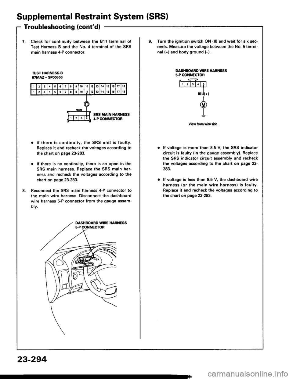
7.Check for continuity between the 811 terminal of
Test Harness B and the No. 4 terminal of the SRS
main harness 4-P conngctor,
oTurn ths ignition switch ON {ll} and wait for six sec-
onds. Measure the voltage between the No. 5 termi-
nal (+) and body ground (-).
TEST HARNESS B07MAZ - SF|D500
OASHSOARO IVIRE HARNESSs.PCO ECTOR
Vraw from sil! rira,
8.
. lf there is continuity, the SRS unit is faulty,
Replace it and recheck the voltages according to
the chart on page 23-283.
. lf there is no cootinuity. there is an open in the
SRS main harness. Replace the SRS main h8r-
ness and recheck the voltages according to the
chart on page 23-283.
Reconnect the SRS main harness 4-P connecto. to
the main wire ha.ness. Disconnect the dashboard
wire ha.ness 5-P connector from the gauge assem-
Dtv.
lf voltage is mora than 8.5 V, the SRS indicator
circuit is faulty (in the gauge assemblyl. Replace
the SRS indicator circuit assembly and recheck
the voltsges according to the chart on page 23-
243.
lf voltage is less than 8.5 V, the dashboard wire
harness (or th€ main wire harness) is faulty.
Replace it and recheck the voltages according to
the chart on page 23-283.
DASHBOARD WIRE HARNESS5.P OONNECTOR
23-294
Page 1403 of 1413
Supplemental Restraint System (SRSI
Airbag Assembly Replacement (cont'd)
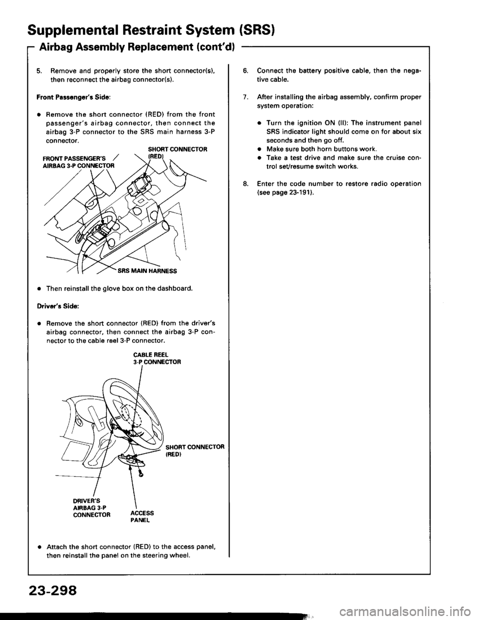
5. Remove and properly store the short connector(s),
then reconnect the airbag connector(s).
Front Pass€ng€r's Side:
. Remove the short connector (RED) from the front
passenger's airbag connector, then connect the
airbag 3-P connector to the SRS main harness 3-P
connector.
. Then reinstall the glove box on the dashboard,
Driver's Side:
Remove the short connector (RED) from the driver's
airbag connector, then connect the airbag 3-P con-
nector to the cable reel 3-P connector.
CABI-E REEL3-P CONNECTOR
SHORT CONNECTORIRED)
DRIVER'SAIRBAG 3.PCONNECTOR
Attach the short connector (RED) to the access panel,
then reinstall the panel on the steering wheel.
SHORT CONNECTOR
FRONT PASSENGER'S ,,'AIRBAG 3.P CONNECTOR
Connect the battery positive cable, then the nega-
tive cable.
After installing the airbag assembly, confirm proper
system operataon:
. Turn the ignition ON (ll): The instrument panel
SRS indicator light should come on for about six
seconds and then go off.
. Make sure both horn buttons work.
a Take a test drive and make sure the cruise con-
trol sevresum€ switch works.
Enter the code number to restore radio oDeration(see page 23-191).
7.
8.
23-294
Page 1409 of 1413
Supplemental Restraint System {SRSI
Cable Reel Replacement (cont'd)
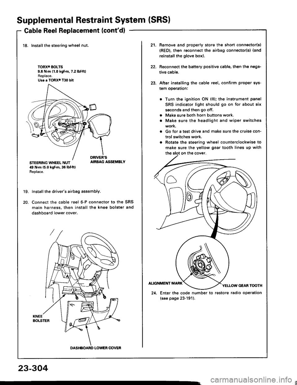
18. Installthe steering wheel nut.
TORXO BOLTS9.8 N.m (1.0 kgf.m,7.2lbtftlReplace.Us6 a TORX6 T30 bit
STEERING WHEEL NUT,19 N.m 15.0 kgt m, 36 lbt ft)Replace.
AIRBAG ASSEMBLY
19.
20.
Install the driver's airbag assembly.
Connect the cable reel 6-P connactor to the SRS
main harness, then install the knee bolster and
dashboard lower cover.
DASHBOARD LOWER OOVER
21.Remove and properly store the shon connector(s)
{RED}, then reconnect the airbag connector(s} (and
reinstall the glove box).
Reconnect the battery positive cable, then the nega-
tive cable.
After installing the cable reel, confirm proper sys-
l€m operalron:
Turn the ignition ON (ll); the instrument panel
SRS indicator light should go on for about six
ssconds and then go off.
Make sure both horn buttons work.
Make sure the headlight and wiper switches
work.
Go for a test drive and make sure the cruise con-
trol switches work.
Rotate the steering wheel counterclockwise to
make sure the yellow gear tooth lines up with
22.
23.
a
a
24. Enter the code number to restore radio operation
(see page 23-191).
23-304
Page 1411 of 1413
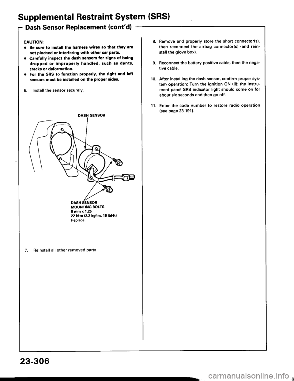
Supplemental Restraint System (SRSI
Dash Sensor Replacement (cont'dl
CAUTION:
. Be 3ure to install the harness wires so that theY ars
not pinchcd or interfering with othor car parte.
o Carefully inspest the dash sensors lor signs of boing
dropped or improperly handled,3uch as dents,
cracks or dsformation.
. For the SRS to lunction propotly, ths right and lsft
sensors must be installsd on the propor sidos.
6. Install the sensor securely.
DASH SENSOR
MOUNTING BOLTS8 mm x 1.2522 N.m (2.2 kgf.m, 16lbfftlReplace.
7. Reinstall all other removed parts.
23-306
li
10.
Remove and properly store the short connector{sl,
then reconnect the airbag connector(s) (and rsin-
stallthe glove box).
Reconnect the battery positive cable, then the nega-
tive cable.
After installing the dash sensor, confirm proper sys-
tem operation: Turn the ignition ON (ll): the instru-
ment panel SRS indicator light should come on for
about six seconds and then go off.
Enter the code number to restore radio operation
(see page 23-191)-
11.
Page 1413 of 1413
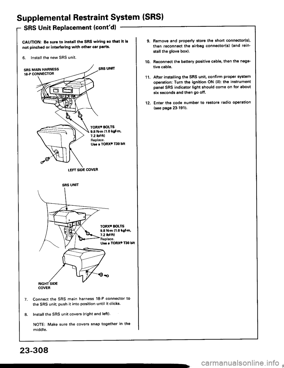
Supplemental Restraint System {SRSI
SRS Unit Replacement (cont'd)
CAUTION: B€ suro to install tho SRS wiring ro thlt it i3
not pinched or interfeling with other car plrts.
6. Install the new SRS unit,
SRS MAIN HARNESS
18.P CONN€CTOR
Ur. . TORX. T30 bit
Connect the SRS main harness 18-P connector to
the SRS unit; push it into position until it clicks.
Install the SRS unit covers (right and left).
NOTE: Make sure the covers snap tog€ther in the
middle.
LEFT SIDE COVER
SRS UNIT
TORX' BOLTS
9.8 N.m 11.0 ksl'm.7.2 tbf.ftlReplace.U.. . TORX' T30 bit
TOD(' BOLTS9.8 N.m (1.0 tc[.m,7.2 tbf.ftl
SRS UNIT
COVER
23-308
1'�l.
12.
Remove and properly storo the short connector{s),
thgn roconnect the sirb8g connector(s) (and rein-
st8ll tho glove box).
Roconnoct the battery positivo cable, th€n the n€98-
tivo cabls.
After installing the SRS unit, confirm proper system
operation: Turn the ignition ON (ll): th€ instrumont
panel SRS indicator light should come on for about
six ssconds and then go off.
Ent6r tho code number to rostors radio operation
(see page 23-191).