1994 HONDA INTEGRA driver door
[x] Cancel search: driver doorPage 11 of 1413
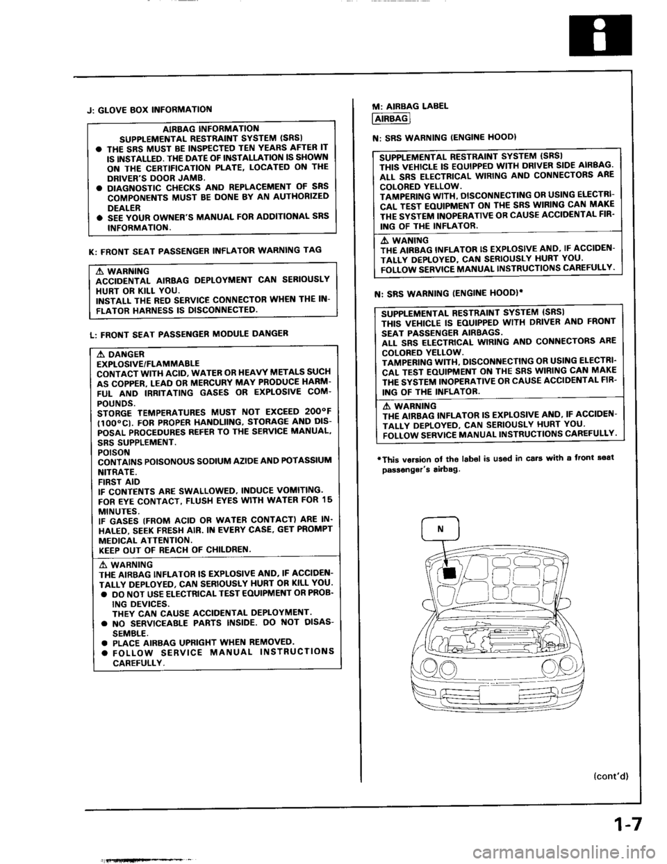
J: GLOVE BOX INFORMATIOf{
AIBBAG INFORMANO
SUPPLEMENTAL RESTiAINT SYSTEM (SRS)
. THE SRS MUST BE INSPECTED TEN YEARS AFTER IT
IS INSTALLED. TI{E DATE OF INSTALLATION IS SHOWN
ON THE CERTTFICATION PLATE, LOCATED ON THE
DRIVER'S DOOR JAMB.
. DIAGNOSTIC CHECKS AND REPLACEMENT OF SNS
COMPONENTS MUST BE DONE BY AN AUTHORIZED
DEALER
. SEE YOUR OWNER'S MANUAL FOR AODITIONAL SRS
INFORMATION.
K: FRONT SEAT PASSENGER INFLATOR WARNING TAG
A WARNING
ACCIDENTAL AIRBAG DEPLOYMENT CAN SERIOUSLY
HURT OR KILL YOU.
INSTALL THE RED SERVICE CONNECTOR WHEN THE IN-
FLATOR HARNESS IS DISCONNECTED
L: FRONT SEAT PASSENGER MODULE DANGER
A DANGER
EXPLOSIVE/FLAMMABLE
CONTACT WITH ACID, WATER OR HEAVY METALS SUCH
AS COPPER. LEAD OR MERCURY MAY PRODUCE HARM'
FUL AND IRRITATING GASES OR EXPLOSIVE COM.
POUNDS.
STORGE TEMPERATURES MUST NOT EXCEED 2OOOF
tlOO"CI. FOB PROPER HANDLIING, STORAG€ AND DIS-
POSAL PROCEDURES REF€B TO THE SERVICE MANUAL,
SBS SUPPLEMENT.
POTSON
CONTAI'\'S POISONOUS SODIUM AZIOE AND POTASSIUM
NITRATE.
FIRST AID
IF CONTENTS ARE SWALLOWED, INDUCE VOMITING.
FOR EYE CONTACT, FLUSH EYES WITH WATER FOR 15
MINUTES.
IF GASES (FROM ACID OR WATER CONTACT) ARE IN.
HALED, SEEK FRESH AIR. IN EVERY CASE. GET PROMPT
MEDICAL ATTENTION.
KEEP OUT OF REACI.I OF CHILDREN.
A' WARNING
THE AIRBAG INFLATOR IS EXPLOSIVE AND. IF ACCIDEN-
TALLY DEPLOYEO, CAN SERIOUSLY HURT OR KILL YOU.
. DO NOT USE ELECTRICAL TEST EOUIPMENT OR PROB.
ING DEVICES.
THEY CAN CAUSE ACCIOENTAL DEPLOYMENT.
. NO SERVICEAALE PABTS INSIDE. OO NOT OISAS-
SEMBLE.
. PLACE AIRBAG UPFIGHT WHEN REMOVED.
. FOLLOW SERVICE MANUAL INSTRUCTIONS
CAREFULLY.
fi{lHfiFe*% _
1-7
M: AIRBAG LABEL
AIRBAG
N: SRS WARNING IENGINE HOODI
SUPPLEMENTAL RESTRAINT SYSTEM (SBSI
THIS VEHICLE IS EOUIPPED WITH DRIVER SIDE AIRBAG.
ALL SRS ELECTRICAL WIRING AND CONNECTORS ARE
COLORED YELLOW.
TAMPERING WITH, DISCONNECTING OR USING ELECTRI-
CAL TEST EOUIPMENT ON TI{E SRS WIRING CAN MAKE
THE SYSTEM INOPERATIVE OB CAUSE ACCIOENTAL FIR'
ING OF THE INFLATOR.
A. WANING
THE AIRBAG INFLATOR IS EXPLOSIVE AND, IF ACCIDEN-
TALLY DEPLOYED, CAf{ SERIOUSLY HURT YOU'
FOLLOW SERVICE MANUAL INSTRUCTIONS CAREFULLY.
SUPPLEMENTAL RESTRAINT SYSTEM {SRSI
THIS VEI{ICLE IS EOUIPPED WITH DRIVER ANO FRONT
SEAT PASSENGER AIRBAGS.
ALL SRS ELECTRICAL WIRING AND CONNECTORS ARE
COLORED YELLOW.
TAMPENING WITI{, DISCONNECTING OR USI G ELECTRI'
CAL TEST EOUIPMENT ON THE SRS WIRING CAN MAKE
THE SYSTEM INOPERATIVE OR CAUSE ACCIDENTAL FIB'
ING OF THE INFLATOB.
A WABNING
THE AIRBAG INFLATOR IS EXPLOSIVE AI{O, IF ACCIDEN-
TALI-Y DEPLOYED, CAN SEBIOUSLY HURT YOU'
FOLLOW SERVTCE MANUAL INSTRUCTIONS CAREFULLY.
N: SRS WARNING IENGINE HOODIi
'This vorsion
passonger's
ol tho labol is u36d in cs.t with a front soat
airbag.
{cont'd)
Page 914 of 1413
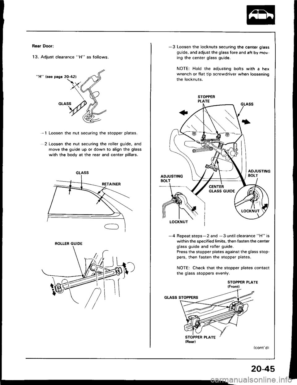
R6ar Door:
'13. Adjust clearance "H" as follows.
"H" lsos page 20-421
- 1 Loosen the nut securing the stopper plates.
2 Loosen the nut securing the roller guide, and
move the guide up or down to align the glass
with the body at the rear and center pillars.
GLASS
ROLLER GUIDE
-3 Loosen the locknuts securing the center glass
guide, and adjust the glass fore and aft by mov-
ing the center glass guide.
NOTE: Hold the adjusting bolts with a hex
wrench or tlat tip screwdriver when loosening
the locknuts.
I
-4 Repeat steps-2 and -3 until clearance "H" is
within the specified limits. then fasten the center
glass guide and roller guide.
Press the stopper plates against the glass stop-
pers, then fasten the stopper plates.
NOTE: Check that the stopper plates contact
the glass stoppers evenly.
STOPPER PLAYElF ontl
204s
Page 918 of 1413

Mirrors
Power Door Mirror Replacement
Hstchback
1. Pry out the cover panel with a flat tip screwdriver,
then remove it.
CAUTION: When prying with a flat tip screwdriver.
w'ap it whh protoctiva tapo to pravont damage.
2. Disconnect the connector. Remove the nuts, then
remove the door mirror while holdino it.
< : Nut locltion3, 3
^^ sxo.8mm I
l$9 111 - to.+ rst.. i| +|lmtu.+rgr.m, I3 lbl'lrl - ---J'/
cot{t{EcToB(Doo. mirror ddol
DOOR MIRROR
CONNECTORlDoor harnoss.ide)
CONNECTOR
3. Installation is the reverse o{ the removal procedure.
Sedan
1. Remove the door panel (see page 20-201 and dis-connect the connector.
2. Pry the cover panel out with a flat tip screwdriver,
then remove the cover panel.
CAUTION: Whsn prying with a flat tip scrowd.lv€l,
wrap it with protectiv€ taps to p.svont damag6.
3. Remove the screws while holding the door mirror.
< i Scrow locations
, A< : Scrow, 2 , B< : Scr6w, I
! ,"",''@ I 66
I s'0.4.- | sro.'"e-.
4 N.m (0.4 kst.m, + w.m (0.4 kgt.m,\3_!!t.rrr__ \!Lbllq
CONNECTOR
4. Installation is the reverse of the removal procedure,
HOOKS
20-49
Page 960 of 1413

Interior Trim
Replacement
a W€al gloves to remove and installth€ trim and panols.a When prying with a flat tip screwd.ivor. wrap it withprotective tap€ to prevent damaga.
NOTE: Take care not to bend or scratch the trim andDanels.
Kick panel/Front pillar trim removal:
l. Remove the kick Danel.
< : Clip locations
A< | Cllp, 1 B< : Ctip, 1 CV : C[p, 1
Jtl,Ml*
U ry-ry
NOTE: Remove the driver's kick panel while pullingthe hood release handle.
KICK PANEL
Pull the door trim back, then remove the front oillarrflm.
< : Clip locations, 4
lnstallation is the reverse of the removal procedure.
NOTE: lf necessary, .eplace any damaged clips.
FRONT PILLAR
20-91
Hatchback
Rear trim panet/Side trim panel/Ouarter pillar trim p-l16moval:
1. Open the hatch.
2. Remove the .ear shelt.
Remove the rear seat (see page 20-'l08).
Remove the trunk mat and spare tire lid.4.
ao..t dr
REAR SHELF
REAR SHELF
TRUNK MAT
SPARE TIRE LID
Page 972 of 1413

Seats
Front Seat Removal
NOTE: Take care not to scratch the seat covers andbodY.
1 . Slide the lront seat backward, then remove th6 bohs,
Slide the front seat forward, then romove the seattrack end covers.
CAUTlOltl: When prying wlth E flat tip scr.wddvor,w.ap lt whh protactive tapo to prevont damago,
> i Eolt locltlon.. 2
3. Remove the bolts.
V:Boh locatlong
A V : Bolt, 1
I'
> : 8olt,
@8 x '1.25 mm Iii i.:iiil..i'xst.^. I16:t'ftt
- /)
4.
NOTE: When insralling, use--iliquid thread lock.
Lift the front seat, then disconnect the connector(driver's).
Carefully remove the front seat through the dooropening.
Installation is the reverse of the removal procedure.
CONNECTOR
20-103
Page 1031 of 1413
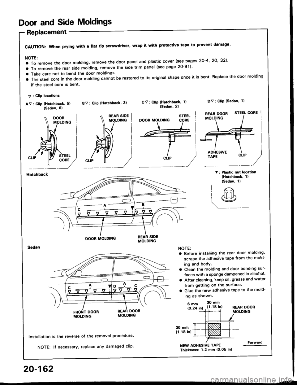
Door and Side Moldings
Replacement
CAUTION: When prying with 8 flal tip screwdriver, wrap it with protective tape to pr€vont damag€'
NOTE:
a To remove the doot moldlng, temove the door panel and plastic cover {see pages 2O-4' 2O' 32],'
a To remove the rear side molding, remove the side trim panel (see page 20-91)
a Take care not to bend the door moldings.
a The steel core in the door molding cann-ot be restored to its original shape once it is bent. Replace the door molding
if the steel core is bent.
V : Clip locations
av : cllp (Hatchb6ck, 5) BV: clip (Hatchback' 3)
V: Plastic nui locatlon(Hatchback, 1)(Sedan, 1)
CV: Cllp (Halchback, 1l{Sodan,2l
Dv: Clip lsodan, 1)
Hatchbsck
20-162
30 mm(1.18 inl
lnstallation is the reverse
NOTE: It necessary,
oJ the removal Procedure.
replace any damaged cliP.NEW ADHESIVE TAPE
Thicknoss: 1.2 mm lo.o5 inl
Forward
STEEL
CLIP
O'
lr>
r9
NOTE:
a BeJore instatling the rear door molding,
scrape the adhesive tape from the mold-
ing and body.
a Clean the motding and door bonding sur-
Jaces with a sponge dampened in alcohol'
a Atter cleaning, keep oil, grease and water
Jrom getting on the surface.
a Glue the new adhesive tape to the mold-
ing as shown.
6mm 30mm
ls 2f 61 . t.l.18 inlREAR DOORMOLDING
Page 1092 of 1413
A/G System Service
Performance Test
The performance test will help determine if the air con-
ditioner system is operating within specitications.
Only use service equipment that is U.L.-listed and is cer-
tified to meet the requirements of SAE J2210 to remove
HFC-134a {R-134a) from the air conditioner system.
CAUTION: Exposure to air conditioner relrig€rant and
lubricant vapor ot mist can irritate eyes, nose and
throat. Avoid breathing the air conditioner rstrigerant
and lubricant vapor or mi3t.
It accidental system discharge occurs, ventilate work
area before resuming service.
R-134a service equipment or vehicle air conditioner sys-
tems should not be pressure tested or leak tested with
comPressed atr.
!@ some mixtures ot air and R'1344 hrv6
been shown to be combustibls at elovatod prsssurel
and can result in firg or explosion causing iniury 01
property damage. Ngvor usg compregsed ail to prossuro
t€st R-134a ssrvice equipment or vohicl€ air conditioner
syst€ms.
Additional health and safety information may be
obtained from the refrigerant and lubricant manufactur-
ers.
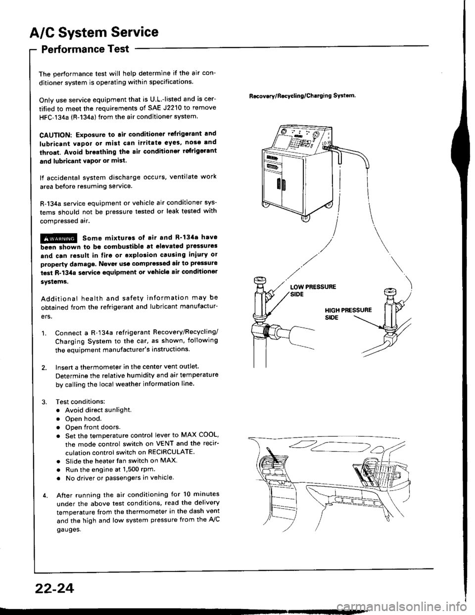
1. Connect a R-134a refrigerant Recovery/Recycling/
Charging System to the car, as shown, iollowing
the equipment manufacturer's instructions.
2. Insert a thermometer in the center vent outlet.
Determine the relative humidity and air temperature
by calling the local weather information line,
3. Test conditions:
. Avoid direct sunlight.
. Open hood.
. Open front doors
. Set the temperature control lever to MAX COOL,
the mode control switch on VENT and the recir-
culation control switch on RECIRCULATE.
. Slide the heater fan switch on MAX
. Run the engine at 1,500 rPm
. No driver or passengers in vehicle.
4. After running the air conditioning for 10 minutes
under the above test conditions. read the delivery
temperature from the thermometer in the dash vent
and the high and low system pressure from the A,/C
gauges.
Rocov.rylB.cycling/Ch!lging SFtrm.
PRESSURELOW
22-24
Page 1119 of 1413
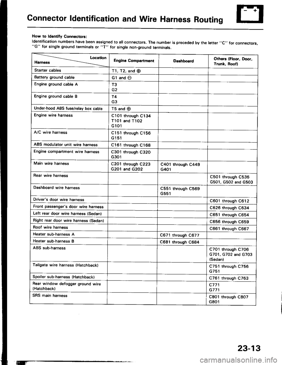
Connector ldentification and Wire Harness Routing
How to ldentity ConnoctolS:
ldentification numbers have been assigned to all connectors. The number is preceded by the letter ,,C,, for connecrors,"G" for single ground terminals ot "f" hr single non-ground terminals.
Location
HamessEngino CompartmontDarhboardOthors (Floor, Door,
Trunk, Rootl
Starter cablesT1, T2, and (E
Battery ground cableG1 and O
Engine ground cable AT3
Engine ground cable BT4
G3
Under-hood ABS fuse/relav box cableT5 and (D
Engine wire harnessC101 through C134
Tl Ol and T102
G 101
A/C wire harnessCl 5'l through C156
G151
ABS modulator unit wir€ harnessC161 through C168
Engine companment wire ha.nessC3O'l through C32O
G301
Main wire hatnessC2O1 through C223
G2Ol and G2O2
C4O1 through C449
G401
Rear wire harnessC501 through C536
G501, G502 and G5O3
DashboSrd wire harnessC551 through C569
G551
Driver's door wire harnessC601 through C612
Front passenger's door wire harnessC626 through C634
Left rear door wire harness (Sedan)C651 through C654
Right rear door wire harness (Sedan)C656 through C659
Roof wire harnessC661 through C667
Heater sub-harness AC671 through C677
Heater sub-hatness BC681 through C684
ABS sub-harnessC7O1 through C7O6
G7O1, G702 and G703(Sedan)
Tailgate wire harness (Hatchback)C751 through C756
Spoiler sub-ha.ness (Hatchback)C761 through C763
Rear window defogger ground wire(Hatchback)c77'l
G771
SRS main harnessC8O1 through C8O7
G801
23-13