Page 1343 of 1413

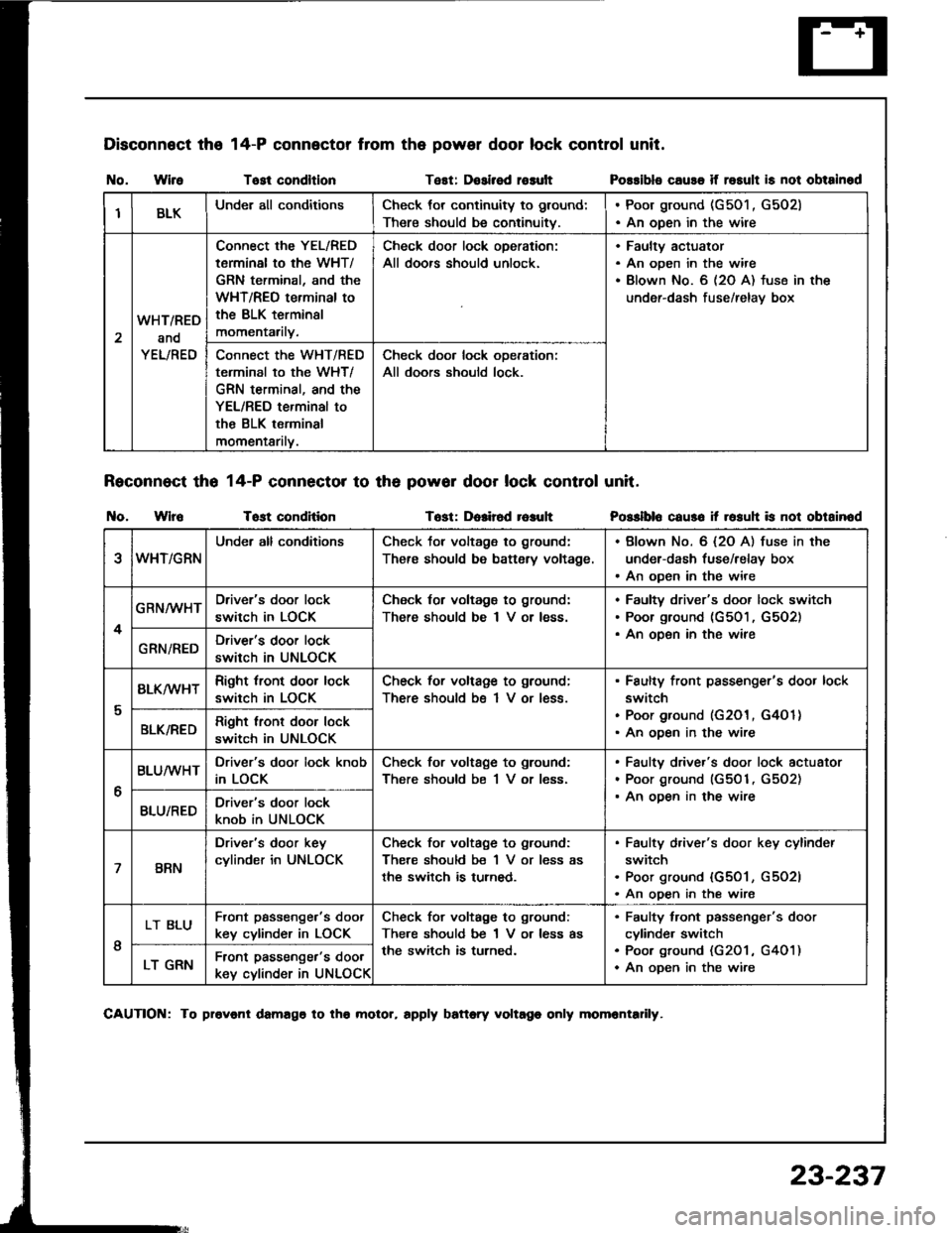
Disconnect the
I{o. WireTost condltlonTest: Dosirsd rosult
Reconnect tho 14-P connector to th6 powor door lock control unit.
t{o. WlroTost conditionTost: Dolir6d r6auh
14-P connector from the power door lock control unit.
Possibls cause if rosult is not obtainod
Posslblo caus6 it rosuh is not obtainod
IBLKUnder all conditionsCheck tor continuity to ground:
There should be continuitv.
. Poor ground (G501 , G502). An open in the wire
2
WHT/RED
and
YEL/RED
Connect the YEL/RED
tarminal to the WHT/
GRN terminal, and the
WHT/REO terminal to
the BLK terminsl
momentarily.
Check door lock oDeration:
All doors should unlock.
Faultv actuator
An open in the wire
Blown No. 6 (2O A) fuse in the
under-dash fuse/relav box
Connect the WHT/RED
terminal to the WHT/
GRN terminal, and the
YEL/RED terminal to
the BLK terminal
momentarilv.
Check door lock ooeration:
All doors should lock.
eWHT/GRN
Under all conditionsCheck tor voltage to ground:
There should be battsry voltage.
. Blown No. 6 {2O A) fuse in the
under-dash fuse/relay box. An open in the wire
4
GRN/WHTDriver's door lock
switch in LOCK
Check for voltagg to ground:
There should be I V or less.
Faultv driver's door lock switch
Poor ground (G501, G5O2)
An oDen in the wireGRN/REDDriver's door lock
switch in UNLOCK
I
BLK/wHTRight tront door lock
switch in LOCK
Check for voltage to ground;
There should bs 1 V or less.
Faulty front passenger's door lock
switch
Poor ground (G201, G4O 1)
An ooen in the wireBLK/REDRight lront door lock
switch in UNLOCK
6
BLUMHTDriver's door lock knob
in LOCK
Check for voltage to ground:
There should be 1 V or less.
Faulty driver's door lock actuator
Poor ground (G501, G5O2)
An ooen in the wireBLU/REDDriver's door lock
knob in UNLOCK
7BRN
Driver's door key
cylinder in UNLOCK
Check for voltage to ground:
There should be 1 V or less as
the switch is turned.
Faulty d,iver's door key cylinder
switch
Poor ground {G501, G5O2l
An open in the wire
I
LT BLUFront passenge.'s doot
key cylinder in LOCK
Check for voltage to ground:
There should be 1 V or less as
the switch is turned.
Faulty tront passenger's door
cylinde. switch
Poo. ground (G201 , G401)
An oDen in the wireLT GRNFront passenger's door
key cylinder in UNLOCK
CAUTION: To provonl damago to tho molor, rpply battory voltago only momrntadly.
23-237
Page 1344 of 1413
1.
Power Door Locks
Driver's Door Lock Actuator Test
Remove the door panel (see section 20).
Disconnect the 6-P connector from the actuator.
Check actuator operation by connecting power and
ground according to lhe table.
CAUTION: To prevont damago lo tho actualol, ap-
ply battery voltage only momentarily.
lf the actualor fails to work properly, replace it.
Terminal
;;"
---\D
LOCK@o
UNLOCKlJ@
23-238
Terminal
il;----tI
LOCKoo
UNLOCKo--o
5. Check fo. continuity between the terminals in each
switch position according to the table.
DOOR LOCK KI{OB
Page 1346 of 1413
Power
Driver'
Door
s Dool
Locks
Key CylinderFront Passenger's Door Key Gylindet
Switch Test
1. Remove the door Danel {see section 2O).
2. Disconnect the 3-P connector trom the switch.
FRONTPASSENGER'SDOOB KEYCYLINDERswtTcH
coN ECIOR
3. Check tor continuitv between the terminals in each
switch position according to the table.
tfil*rr
Terminal
P""ft;---lABc
LOCKo----o
OFF
UNLOCKo----o
UNLOCK
-r--O
I LOCK
Switch Test
1. Remove the door panel (see section 20).
2. Disconnect the 2-P connector from the switch.
terminal side
3. Check for continuity between the terminals in each
switch position according to the table.
Position
TerminalB
UNLOCKGo
OFF
UNLOCK<
I
23-240
Page 1410 of 1413
Dash Sensor Replacement
GAUTION:
. Oo not drmrgc the sensor wiring.. Do not instrll used SBS part3 from anothor c!t,When repairing an SRS: use only new part3.o Roplaco. 3onsor it it is dented, crackod, or doform.od.
NOTE; The original radio has a coded theft protectioncircuit. 8e sure to get the customer,s code numberbefore disconnecting the b€ttery cabres,
1. Oisconnect the battery negative cable and then theposative cable.
2. Remove the glove box damper (see section 201.then remove the glove box.
SHOBT CONNECTORIREDI
3. Connect the short connector(s) to the airbag(s).
DRIVER'SAIRBAG
DRNEN'SANAAG3.P CONNECTORSHORTCONNECTORIREDI
SRS MAIN HARNESS
Remove the footrest driver,s side only and door sillmolding, then pull the carpet back, and remove thedash sensor protector. (Left side shownj right sideis similar.)
DASHPROTECTOR
5. Remove the two mounting bolts. then remove thedash ssnsor.
(cont'd)
DASH SENSOB
MOUNTIITG BOLTS
23-305