Page 959 of 1413

Moonroof
Opening Drag Check
(Motor Removed)
Before installing the motor. measure the effort required
to open the glass using a spring scale as shown
CAUTION: Whon using a spring scalo. protoct the
l€ading odge ol the glass with a shop tow€I.
lf load is over 40 N (4 kgl, 9lbt), check side clearance
and glass height adiustment (see page 20-85)'
Closing Force Check
lMotor Installed)
1. After installing all removed parts, have a helper hold
the switch to close the glass while you measure
force required to stop it. Attach a spring scale as
shown. Read the torce as soon as the glass stops
moving, then immediately release the switch and
spring scale.
CAUTION: When using a sp ng scala. protect th€
leading odge ol the glass with a shop towel'
Closing Force: 200-290 N
120-30 ksf. 44-66 lbf)
lf the lorce is not within specification, install a new
lock washer. adjust the tension by turnang the mo-
tor clutch adjusting nut, and bend the lock washe.
against the motor clutch adjusting nut.
GLASS
\
clocKwlsE /i 1 coutren-
To increase l, ctocKwlsE
torce, I Io decreaseforce
L.
20-90
--
Page 969 of 1413

Headliner
9, Lower the headliner as shown.
NOTE: Take care not to bend and scratch the
headliner.
Replacement {cont'd)
LEFT OUARTER PILLAR
TRIM PANEL
11.
RIGHT OURTER PILLARTRIM PANEL
1O. Bemove the headliner through the hatch opening'
Installation is the reverse of the removal procedure.
NOTE:
a When inserting the headliner through the hatch
opening, be careful not to fold or bend it. Also,
be careful not to scratch the bodY.
a Check that both sides of the headliner are secure-
ly attached to the trim and Panels.
a When installing the roof trim, install the Joint
toward the rear.
20-100
HEADLINER
HEADLINER
Sodan
'1.Remove:
a Center Dillar lower trim (see page 20-94)
a Front and rear door trim lsee page 20-94)
a Front pillar trim (see page 2O-9 .
a Center pillar trim (see page 20-94)
a Rear pillar trim panel (see page 20 95)
a Rearview mirror (see Page 20-521
Remove the sunvisor and holder from each side
: Screw locationS, 6
2.
^l
s,1
LOCK WASHER
loutsidel
HOLDER
/
$-.unu,"o"
/' BRACKET
NOTE:
a lf necessary, remove the sunvisor bracket as
shown.
a When installing the sunvisor bracket, apply grease
and make sure it's installed properly.
,@
suNvrsoR
Page 971 of 1413
Headliner
Replacement {cont'd)
5. Remove the .ool trim (moonroof modell.
6. Detach the clips by sliding the headliner forward.
A : Clip locations, 3
HEADLINER
Remove the headliner through the passenger's door
opening.
lnstallation is the reverse ot the removal procedure
NOTE:
a When inserting the headliner through the door
opening. be careful not to fold or bend it. Also,
be careful not to scratch the body
a Check that both sides ot the headliner are secure-
ly attached to the trim and Panels.
a When installing the roof trim, install the joint
toward the rear.
)
HEADLINER
20-102
Page 991 of 1413

Seat Belts
lnspection
Retractol InsDection
1. Before installing the retractor, check that the seat
belt can be pulled out freely.
2. Make sure that the seat belt does not lock when the
retractor is leaned slowly up to 150 from the mount-
ed oosition. The seal belt should lock when the
retractor is leaned over 4O".
CAUTION: Do
tgtractol.
Hatchback
Forwald -
Rear:
not attempt to disassemble the
' : Mounted Position
RETRACTOB
Iniid6
Sedan
Front:
Forwardlnsido
Forward
Rear:
RETRACTOR
3. Replace the seat belt with a new one if there is any
abnormality.
On-the-Cal S€at Belt Inspection
1 . Check that the seat belt is not twisted or caught on
anythrng.
After installing the anchors, check lor free movement
on the anchor bolts. lf necessary, remove the anchor
bolts and check that the washers and other pans are
not damaged or improperly installed.
Check the seat belts for damage or discoloration.
Clean with a shop towel iI necessary.
CAUTION: Use only soap and water to clean.
NOTE: Dirt build-up in the metal loops of the upper
anchors can cause the seat belts to retract slowly.
WiDe the inside of the loops with a clean cloth damp-
ened in isopropyl alcohol.
Check that the seat belt does not lock when pulled
out slowly. The seat belt is designed to lock only dur-
ing a sudden stop or impact.
Make sure that the seat belt will retract automata-
cally when released.
Replace the seat belt with a new one it there is any
abnormality.
2.
3.
4.
20-122
Page 999 of 1413
Front and Rear Consoles
Replacement (cont'd)
7. Remove the Jront console as shown.
NOTE: Wrsp the selecter lever and A/T gear posi-
tion indicator psnel with a shop towel to prevent
damage.
20-130
8. It necessary, disassemble the Jront and rear
consoles.
: Scrow locations, 5
Ai
_Y_)
CONSOLE PANEL (M�TI
SHIFT LEVERBOOT (M/TI
: Scraw locations, I
AI
Y,/
REAR CONSOLE
PARKING BRAKECOVER
COVER SETPLATE
9. Installation is the reverse of the removal procedure.
CONSOLE
ARMREST
cof{solE Box
Page 1006 of 1413

Replacement
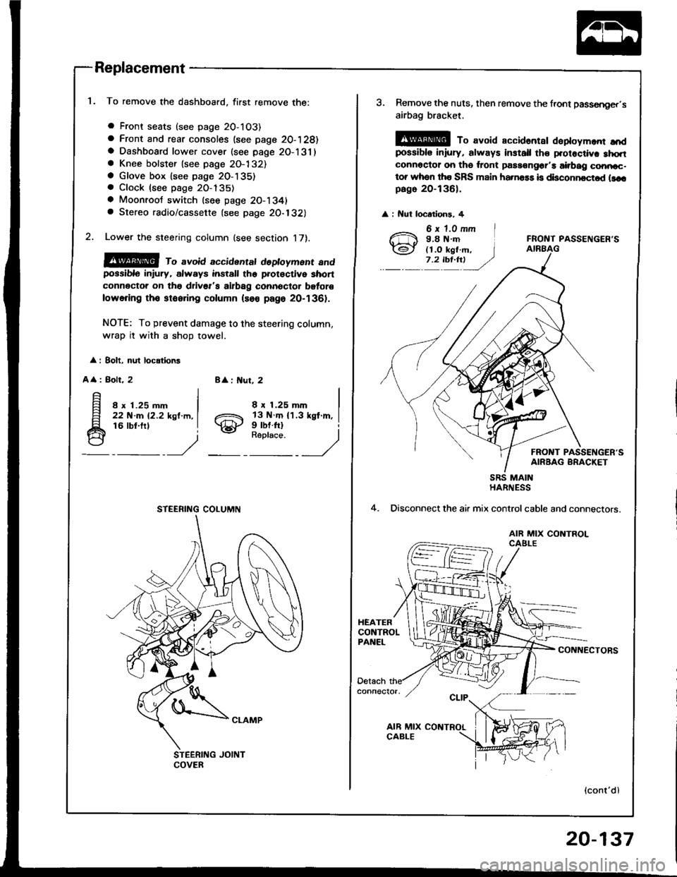
To remove the dashboard, first remove the:
a Front seats (see page 2O-103)
a Front and rear consoles (see page 20-128)a Dashboard lower cover (see page 2O-131)a Knee bolster (see page 2O-132)a Glove box lsee page 2O-135). Clock (see page 20-135)
a Moonroot switch (see page 20-1341a Stereo radio/cassette {see page 20-132)
Lower the steering column (see section 17).
@@ ro avoid accidentat dedoyment andpossiblo in ury, always install the prot€ctive short
connector on tho drivsr's airbag connector bgtor€
lowering tho stooring column (so€ page 20-1361.
NOTE: To prevent damage to the steering column,
wrap it with a shoD towel.
: 8olt, nul locations
A
: Bolt, 28 : ut, 2
8 x 1.25 mm22 N-m 12.2 ksl.m,16 lbt.frl
8 x 1.25 mm
gill$"'l
STEERING COLUMN
3. Remove the nuts, then remove the front passsnger,s
airbag bracket,
@ To avoid accidantar daploym.nr ",'dpossibls iniury, always install th€ protoctiv. 3hqtconnoctor on tho ,ront passongor'a airbag conncc-tor whon tha SRS main ha.na$ is disconncctod llcrpago 20-136).
: Nut locatlons, 4
FRONT PASSENGER'S
FRONT PASSENGER'SAIRBAG BRACKET
4.
SRS MAINHARNESS
Disconnect the air mix controlcable and connectors.
AIR MIX CONTROLCAELE
CONNECTORS
(cont'dl
20-137
Page 1007 of 1413

Dashboard
Replacement (cont'd)
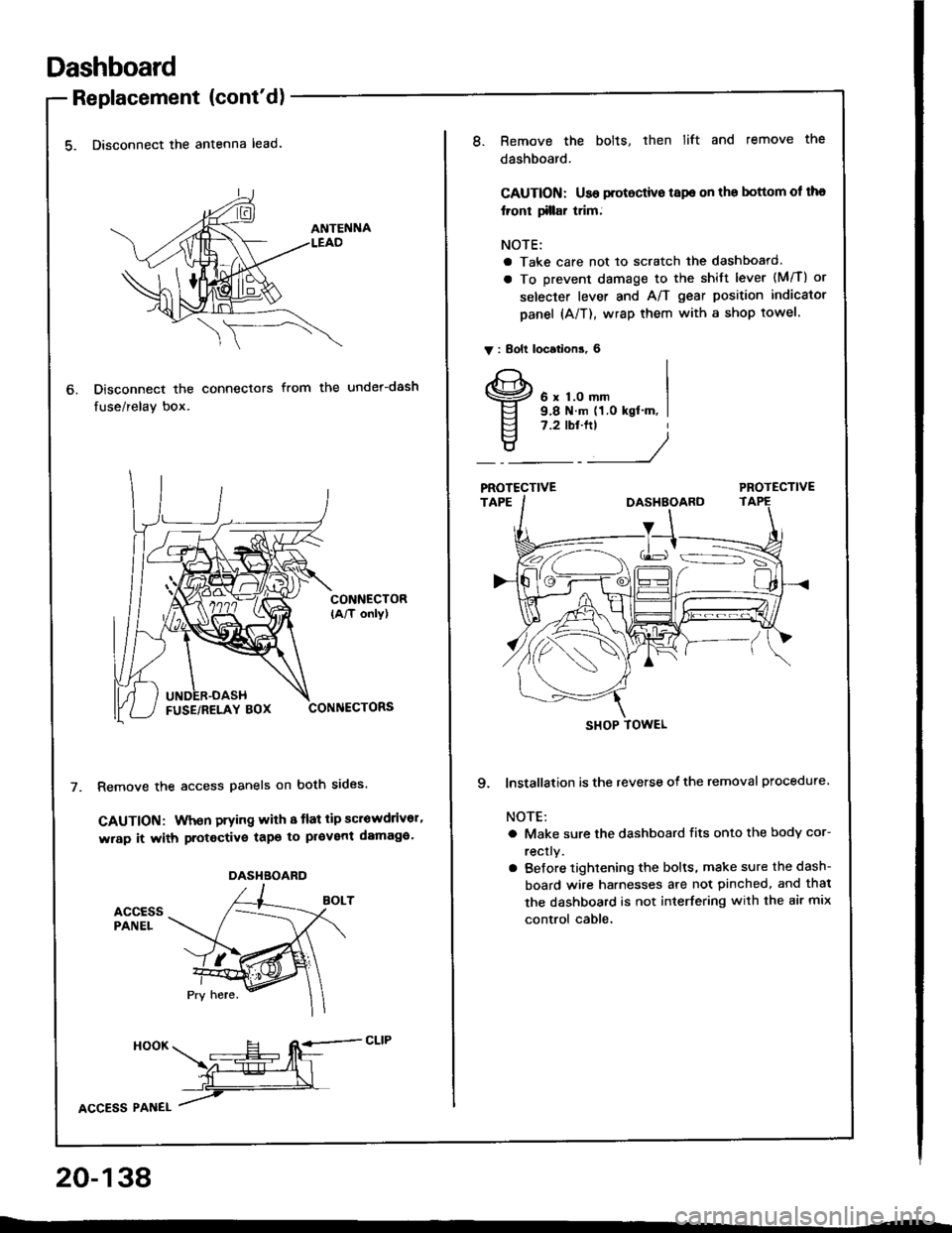
5. Disconnect the antenna lead.
Disconnect the connectors
fuse/relay box.
from the under-dash
CONNECTOR(A/T only)
CONNECTORS
Remove the access panels on both sides.
GAUTION: When prying with 8 tlat tip scrowdrivor'
wrap it with protective tapo to pl€vent damaga'
accEssPANEL
6.
DASHBOARD
HooK ___E-- RE=-cLrP
ffiL
lcCesS Plnel /
20-138
8.Remove the bolts, then lift and remove the
dashboard.
CAUTION: Use protoctive tspe on the bottom ol tha
lront tillar trim;
NOTE:
a Take care not to scratch the dashboard.
a To prevent damage to the shift lever (M/T) or
selecter lever and A/T gear position indicator
panel (A/T), wrap them with a shop towel.
V : Bolt locations, 6
6 x 1.0 mm9.8 N.m (1.0 kgt'm, I7.2 tbt.ftt
____/
PROTECTIVE
9. lnstallation is the reverse of the removal procedure
NOTE:
a Make sure the dashboard fits onto the body cor-
rectly.
a Before tightening the bolts, make sure the dash-
board wire harnesses are not pinched, and thal
the dashboard is not interfering with the air mix
control cable.
SHOP TOWEL
Page 1027 of 1413
Retainers and WeatherstriP
Replacement
CAUTION: Wear gloves to lemov€ and install tho i€tain€rs'
NOTE: Take care not to bend the retarners.
< : Screw localions, 19 < : Clip locations, I
| .€\
!:
l{SHOP TOWELq
CENTER PILLARMOLDING
Boot side section:
I
RETAINER
lnstallation is the reverse of the removal procedure.
NOTE:
a Check the weatherstrip lor damage or deterioration, and replace if necessary'
a After installing the weatherstrip, check for water leaks'
a lf necessary, adjust the position of the door glass (see page 20-40)
a It necessarv, replace any damaged clips.
Center oillar section:
FRONT CENTER PILLAR
CENTER PILI-ARMOLDING
NOTE: The numbers atter the part names
show the quantities ot the parts used
!9
RETAINER
WEATHERSTRIP
REAR CLIP
RETAINER
WEATHERSTRIP
20-158