Page 263 of 1413

PGM-FI System
Knock Sensor (KS) tB18C1 enginel
ml- nl: The Malfunction Indicator Lamp (MlL) indicates Diagnostic Troubte Code (DTC) 23: A probtem inthe Knock Sensor (KS) circuit.
a6l--fzt.i--1/.---r+\
ware sido
o ooooo ooo ooo o looooooooo oooo ooo oo ooo I oooo oooo
11-74
- The MIL h6s boon r6port6don.- With th6 SCS ahort connec-tor connoctod (soe pago11-341, codo 23 is in-dicrtod.
Oo the ECM Reset Proceduro (seepage 11-35).
Start the engine. Hold the engineg!-3,Opq rpm with no load {A/T in
Lryl orlPlposirion, M/T in neurra until the radiator fan comes on,then let it idle.
Hold the engine at 3,0O0-4,000rpm for 10 seconds.Intomittor failure, ay5-t.m is OK at this tim6(teat drivo mav bonec€saary,.Chock tor Door connec-tion3 or loo3o wlaos etC222 {locatod 6r ghrshock tow6r), Cl33(KSl and ECM.Turn the ignition swirch OFF.
Connect the test harness to themain wire harness only, not to theECM (see page 1 1-37).
Check for continuity between D3terminal and body ground.
Ropdr short in RED/BLUwiro b€tweon ECM {D3land ths Ks.
(To page 11-75)
Page 271 of 1413

ldle Control System
ldle Air Control (lACl Valve
lt6l- -l lf l- The Maltunction Indicator Lamp (MlL) indicates Diagnostic Trouble Code {DTC} 14: A problem in
' '- the ldle Air Control llAC) Valve circuit.
The IAC Valve changes the amount of air bypasEing the throttle body in respons€ to a current signal from the ECM in
order to maintain the proper idle speed.
ffi: r;611/ | /--T-\
- The MIL h.3 been report don,- With tho SCS shon connoctolconnoctod (soo pago 'l 'l -341,
cod6 14 is indicatod.
Do the ECM Reset Procedure (seepage 11-35).
With the engine running snd theaccelerator pedal releas€d, dis-conn€ct th€ 2P connector frorttho IAC valvo.
ls the MIL on and does it indicatecode 14?
htarmitlaot frlu]., aya-t.m i. OK !t thir tlft.
ll.rl drlv. mly ba nac-aaaaryl.Chack tor Doo. conn€c-tlonr oi loora wirca atC3O5 (loc.t.d .t |.ftlhock tow.tl, C424,Cl tB (lAC v.lvol .ndECM.
Disconnect the 2P connector fromthe IAC valve.
Sub.iituto . known{ood IACvdva lnd iotolt.
{To page 11-83}
11-82
Page 289 of 1413

The fusl supply system consists ot a fuel tank, in-tank
high presssure fu6l pump, PGM-FI main relay, fuel filter,
tuel pressure regulatot, fuel inioctors, fusl pulsation
damper and fuol delivery and return linss. This system
delivers pressure-regulatored fu6l to the fu6l injectors and
cuts the fuel delivory wh6n the engine is not running.
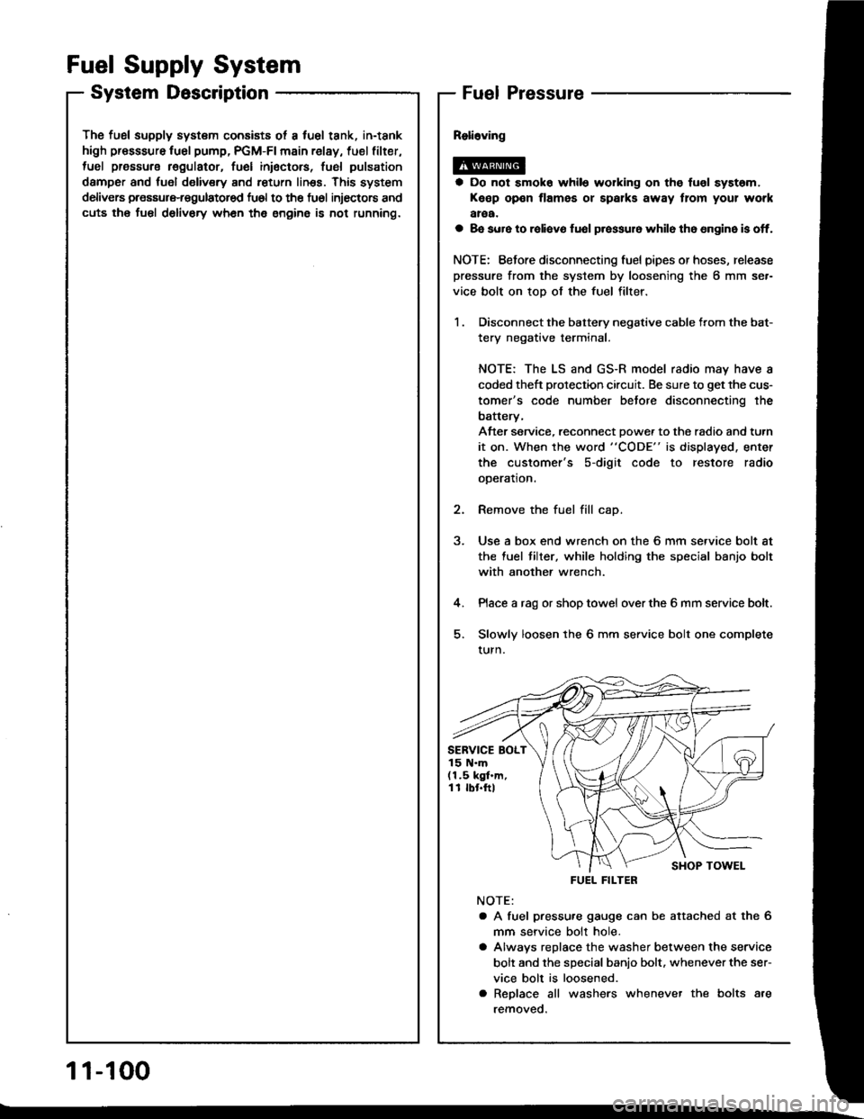
Fuel Supply System
System DescriptionFuel Pressure
a Do not smok6 while working on the fuol syst6m,
Keep open flames or spalks away tlom your work
aroa.
a 8e sure to raliavo fuol p.essur6 while th6 6n9in6 is off.
NOTE: Eefore disconnecting fuel pipes or hoses, release
pressure from the system by loosening the 6 mm se.-
vice bolt on top of the fuel filter.
1 . Disconnect the battery negative cable from the bat-
tery negative terminal.
NOTE: The LS and GS-R model radio may have a
coded theft protection circuit. Be sure to get the cus-
tomer's code number betore disconnecting the
batterv,
After service, reconnect Dowe. to the radio and turn
it on. When the word "CODE" is displayed. enter
the customer's s-digit code to restore radio
ooeration.
2. Remove the fuel fill cap.
3. Use a box end wrench on the 6 mm service bolt at
the fuel tilter, while holding the special banjo bolt
with another wrench.
4. Place a rag or shop towel over the 6 mm service bolt.
5. Slowly loosen the 6 mm service bolt one complete
turn.
NOTE:
a A fuel pressu.e gauge can be attached at the 6
mm seryice bolt hole.
a Alwavs replace the washer between the service
bolt and the special banio bolt. whenever the ser-
vice bolt is loosened.
a Replace all washers whenever the bolts are
removeo.
SERVICE BOLT15 N.m(1.5 kgf.m,11 rbr.ftl
FUEL FILTER
1 1-100
Page 294 of 1413

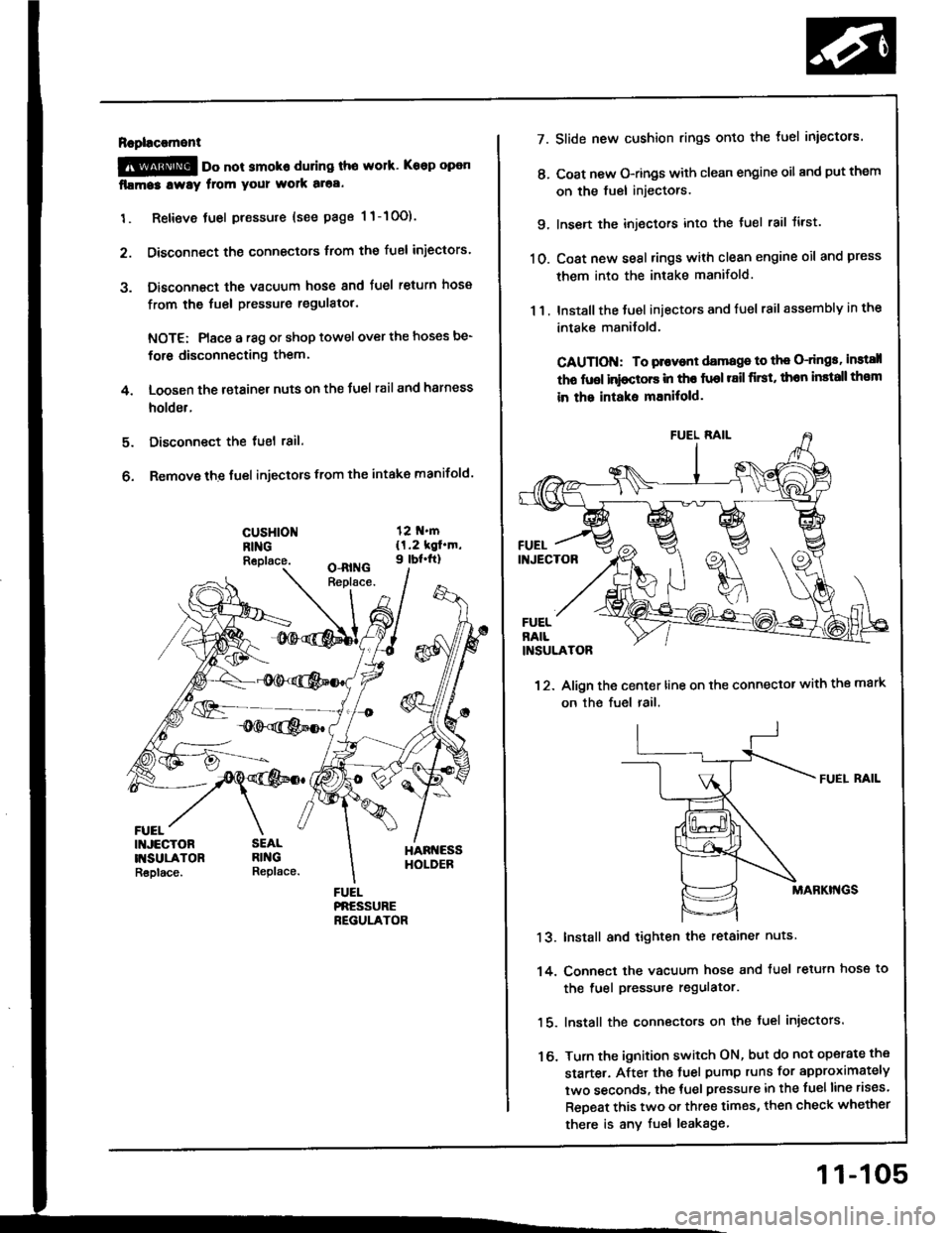
Rapl!c!ment
@ oo not smoko during tho work. Keep open
fllma3 lway from your wolk aloa.
1. Retieve tuel pressure {see page 1 1-10O).
2. Disconnect the connectors trom the fuel iniectors.
3. Disconnect the vacuum hose and fuel return hosa
from the fuel pressure regulatol.
NOTE: Place a r8g or shop towel over the hoses be-
for6 disconnecting them.
4. Loosen the retainer nuts on the Juel rail and harness
holder.
Disconnect the tuel 18il.
Remove the fuel injectors from the intake manifold.
5.
6.
cusHloNRINGReplace.
FUEL
7.
t'.
9.
10.
13.
14.
16.
11.
Slide new cushion rings onto the luel iniectors.
Coat new O-rings with clean engine oil and put them
on the fuel injectors.
Insen the injectors into the tuel rail tirst.
Coat new seal rings with clean engine oil and press
them into the intake manifold.
Install the Juel iniectors and fuel rail assembly in the
intake manilold.
CAUTION: To plovont damage to th€ O-dngs, instsll
tho fuol inioctors in tho fuol r8il first, thon install th€m
in the intaks mEnitold.
12. Align the center line on the connector with the mark
on the fuel rail.
FUEI. RAIL
MABKI'{GS
Install and tighten the retainer nuts
Conn€ct the vacuum hose and tuel retuln hose to
the fuel pressure regulator.
lnstall the connecto.s on the fuel injectors.
Turn the ignition switch ON, but do not operate the
starte.. After the tuel pump runs for approximately
two seconds, the tuel pressure in the fuelline rises.
ReDeat this two or three times, then check whether
there is any fuel leakage
11-105
Page 296 of 1413
Raplacoment
@ oo not amoko whil6 working on fuel sys-
tam. Koop open flamo away tlom your work atea'
1. Place a shop towel under the fuel pressure regula-
tor, then reliev€ tuel pressure (see page 1l-10O).
2. Disconnect the vacuum hose and fuel return hose.
3. Remove the two 6 mm retainer bolts.
12 N.m{1.2 kgl.m,9 rbf.ft)
NOTE:
a Replaco the O-ring.
a When assembling the fuel pressure regulator, ap-
ply clean engine oil to the O-ring and assemble
it into its proper position, taking care not to
damage the O-dng.
Rsplace.
11-107
Page 297 of 1413

Filter
Fuel Supply System
Fuel
a Do not smoko while wo*ing on tusl system.
Keop open tlame away ftom your wotk area.a While replaclng th6 tusl liher, be caletul to koop a safodistanc6 betweon battery torminals and any tool3.
The Juel filter should b€ replaced every 4 years or 60,0O0miles (96,OOO km), whichever comes f irst. or wheneverthe fuel pressure drops below the specilied value
127 5 - 324 kPa, 2.8 - 3. 3 kgJ/cmr, 40-47 psi (Bl 8C 1engine: 329-378 kPa, 3.35-3.85 kgf/cmr, 48-55psi) with the fuel pressure regulator vacuum hose dis-
connectedl afte. making sure that the tuel pump and thefuel pressure regulator are OK.
1 , Disconnect the battery negative cable trom the bat-
tery negative terminal.
NOTE; The LS and GS-R model radio may have acoded theft protection circuit, Be sure to get the cus-
tomer's code number before disconnecting the
batterv.
After service, reconnect power to the tadio and turn
it on. When the word "CODE" is displaved, enter
the customer's 5-digit code to restore radio
operation.
2. Place a shop towel under and around the fueltilter.
3. Relieve fuel pressure (see page 11-100).
4. Remove the special banio bolt and the fuel feed pipe
from the fuel tilter.
Remove the fuel filter clamp and tuel Jilter.
When assembling, use new washers, as shown,
NOTE: Clean the llared joint ot high pressure hoses
thoroughly before reconnecting them,
1 1-108
SPECIALBOLT33 N.m(3.4 kgt.h,25 rbf.ft)
SERVICE BOLT15 N.m ll.5 kgt.m,1 I rbr.ftl
WASHERReplace
1O ttl.m(1.O kgf.m,7 tbt.ftl
Page 335 of 1413
Clutch Master Cylinder
Removal/lnstallation
CAUTION:
a Do not sgill b.ake lluid on the car; it may damags the
painl; it biake fluid does contact tha paint. wash it
otf immediately with water.
a Plug lhe end ot the clutch pips and r€servoil hose with
a shop towel to prsvent blake fluid ttom coming out.
1. Remove the brake fluid from the clutch master
cylinde. reservoir with a syringe.
2. Disconnect the clutch oioe and reservoir hose from
the clutch master cvlinder.
CLUICH PIPE15 N'm {1.5 kgl.m,1 1 tbf.ftl
CLUTCHMASTERCYLINDER
Pry out the cotter pin. and pull the pedal pin out ot
the yoke. Remove the nuts.
NUTS13 N.m {1.3 kgf.m,9 lbt.frl
Remove the clutch master cylinder.
NOTE: Do not spill brake fluid on the
cylinder damper.
OAMPERCLUMAIcYL
Install the clutch master cylinder in
der of removal.
NOTE: Bleed the clutch hydraulic s\
12-61.
clutch master
CLUTCHMASTERCYLINDER
!l rn Ine reverse or-
c system (see page
12-5
Page 382 of 1413

Mainshaft Thrust Clearance
Adjustment (cont'd)
MAINSHAFT
-),.
"7t/'-
'..' .'i'
-7. Slide the mainshaft base over the mainshaft.
i.�,
MAINSHAFT BASE07GAJ - PG20130
-8. Attach the mainshaft holder to the mainshaft as fol-
NOTE:
. Back-out the mainshaft holder bolt and loosen
the two hex bolts.
. Fit the holder over the mainshaft so its lip is
towards the transmission.
. Align the mainshaft holder's lip around the
groove at the inside ot the mainshaft splines,
then tighten the hex bolts.
MAINSHAFT HOLOERBOLT
f- t{-c
lnrTh l
ex
| \-_.r' ._/_/ lrl Borrs
L ___E_J
\MAINSHAFTHOLDER07GAJ - PG20110
MAINSHAFT BASE07cAJ _ PG20130
-9.Seat the mainshaft fully by tapping its end with a
plastic hammer.
-10.Thread the mainshaft holder bolt in until it just con-
tacts the wide surface of the mainshaft base.
- 1 1. Zero a dial gauge on the end of the mainshaft.
12.Turn the mainshaft holder bolt clockwise; stop turn-
ing when the dial gauge has reached its maximum
movement. The reading on the dial gauge is the
amount of mainshaft end play.
CAUTION: Turning the mainshaft holder bolt mor€
than 60 degrees after the needle ol the dial gauge
stops moving may damage the transmission,
DIAL GAUGE
MAINSHAFT HOLDER07GAJ - PG201r0
- 13.lf the reading is within the standard, the clearance is
correq.
lf the reading is not within the standard, recheck the
shim thickness.
Standard: 0.11 - 0.18 mm {0.004 - 0.007 in)
\
13-40