Page 1300 of 1413

Stereo
Power
Sound
Antenna
System
Motor Test
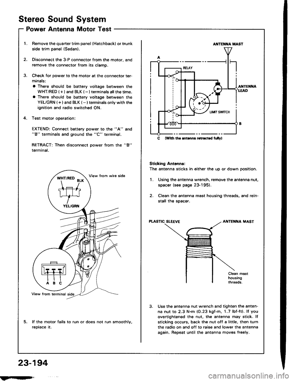
Remove the quarter trim panel (Hatchback) or trunk
side trim panel (Sedan).
Disconnect the 3-P connector from the motor, and
remove the connector from its clamD.
Check for power to the motor at the connector ter-
minals:
a There should be battery voltage between the
WHT/RED (+l and BLK {-} terminals all thetime.a There should be battery voltage between the
YEL/GRN {+) and BLK (-} terminals onlv with the
ignition and radio switched ON.
Test motor oDeration:
3.
4.
EXTEND: Connect battery power to the "A"
"B" terminals and ground the "C" terminal.
8no
"4"RETRACT: Then disconnect power trom the
terminal,
lf the motor fails to run or does not run smoothlv,
reDtace tr.
*ft'^to
?r*
TIFIT*r'
YEL/GRN
AI{TE T{A MAST
AI{TEI{I{ALEAD
C ftYhh lha lnLnn. r.tr.ci.d t|Ilyl
Sticking Ant6nna:
The antenna sticks in either the up or down position.
1.Using the antenna wrench, remove the antenna nut,
spacer (see page 23-195).
Clean the antenna mast housing threads, and rein-
stall the soacer.
PLASTIC SLEEVEAIITENNA MAST
Cloan masthousingthroads.
Use the antenna nut wrench and tighten the anten-
na nut to 2.3 N.m (0.23 kgf-m, 1.7 lbf-tt). lJ you
overtightened the nut. the antenna may stick. lf
sticking occurs, back the nut off a little, then turn
the radio on and off to raise and lower the antenna
again. Repeat until the antenna moves treely.
23-194
fmft,
Page 1305 of 1413
Horn
Component Location Index
CAUTION:
a All SRS €lectricsl wiring harnesses al€ covered with
yellow insulation.
a B€fore disconnecting any part of the SRS wiro har-
neaa, connect tho short connectol(sl.a Replaco the entire aftected SRS harness assembly ifit haa an open circuit ot damaged wiring.
HORNTest, page 23'2O3
HORN SWITCHESTest, pago 23-2Ol
UNDER.DASHFUSE/RELAY BOXCABLE REELRepfacement, page 23-302
HORN RELAY
I Wiro coloB: BLU/RED, BLK, IIWHT/GRN, and BLU/GR lTest, page 23-68
{Covo.ed wiih yollow insulationl
<------\-\----.....=
23-199
Page 1307 of 1413

Switch Test
CAUTION:
a All SRS el6ctrical wiring harnossos are covarod withyellow inaulation.
a Beforo disconnecting any pan ot the SRS wire har-neaa, connoct ths short connector(s).a Roplace the entil€ afloctod SRS harne$ a$6mbly ifit has an open circuit or dsmagad wlring.
NOTE; The original radio has a coded theft protection
circuit. Be sure to get the customer's code number before- disconnecting the battery.- removing the No. 32 {7.5 A) fuse lrom the under-hoodtuse/relav box.- removing the radio.
After service, reconnect power to the radio and turn iton. When the word "CODE" is displayed, enter the cus-tomer's 5-digit code to restore radio operation.
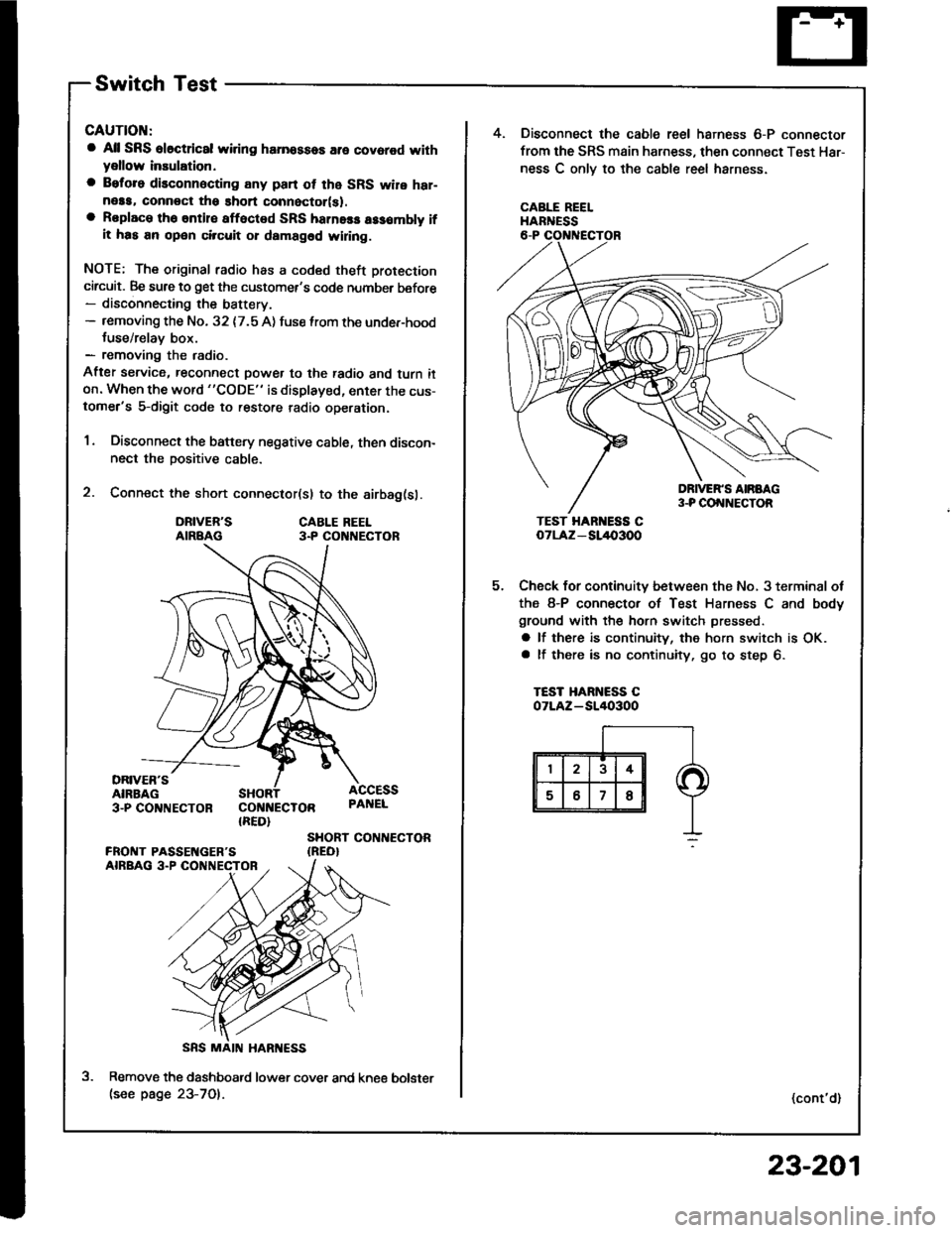
1. Disconnect the battery negative cable, then discon-nect the positive cable.
2. Connect the short connector(sl to the airbag(sl.
DRIVER'SAIRBAGCABLE REEL3.P CO NECTOR
DRIVER'SAIRBAG3-PCO'TNECTOR COI{NECTOR{RED}
ACCESSPAI{EL
SHORT CONTIECTOR{REO}
Remove the dashboatd lower cover and kne€(see page 23-701.
5.
4. Disconnect the cable reel harness 6-P connector
from the SRS main harness, then connect Test Har-
ness C onlv to the cable reel harness.
CABLE REELHARNESS
TEST HAR ESS CoTLAz - SL/l{,3OO
Check for continuity between the No, 3 terminal ot
the 8-P connector of Test Harness C and body
ground with the horn switch pressed.
a lf there is continuity, the horn switch is OK.a lf there is no continuity, go to step 6.
TEST HARNESS COTLAZ-SI/I()3OO
(cont'd)
bolster
23-201
Page 1309 of 1413
MOUNTI G AOLT
t.
2.
5.
Horn Test
Remove the front bumper (see page 23-164).
Disconn€ct the 2-P connector from the hofn.
Remove the horn.
2-P COt{t{ECTOB
4. Test the horn by connecting battery power to oneterminsl and grounding the other, The horn shouldsound.
5. Reolace the horn if it fails to sound.
23-203
Page 1312 of 1413
Rear Window Defogger
Component Location Index
CAUTION:
a All SRS olectrical wi ng ham€$6s are covoled with
y€llow insulation.
B6foro disconnocting any part of ths SRS wire har-
ness. connoct tho short connector(s).
Roplacs the ontire affectod SRS harness assombly if
it has an open circuit or damagcd wiring.
REAB WINDOWDEFOGGER RELAYTest, page 23-68
REAR WINDOWDEFOGGER SWITCHRemoval, page 23-209Test, page 23-2Og
REAR WINDOW DEFOGGERTest, page 23-210
UI{DER.DASH FUSE/RELAY BOX
REAR WINDOW DEFOGGER TIMER CIRCUIT
{ln the integrated control unil)fnput Test, page 23-147
SRS MAII{ HAR'{ESS
The rear window defogger is controlled by the integrated control unit, Pushing the defogger switch in the instrument
panel it sends a signal to the defogger time. in the integrated control unit, and the detogger stays on tor 25 minutes
or until the ignition switch is turned off. The indicator light in the switch comes on when the deJogger works.
23-206
Page 1317 of 1413
Moonroof
Gomponent Location lndex
a All SRS oloctrical wiring harnesses aro covared withyellow insulation,
a Eoforo disconnocting any part of tho SRS wire har-neaa, connoct th6 shon connector(sl.a Roplace th6 entire 8ff6cted SRS harness assombly ifit has an open circuit or damaged widng.
MOO BOOF SWTTCHRemov8l, page 23-214Test, page 23-215
SRS MAIN HARI{ESS{Covered with yellow insulation)
MOO ROOF MOTORTest, pag€ 23-215Replacoment, section 20
23-211
Page 1322 of 1413
Power Mirrors
Component Location Index
POWER MIRRONSTest, page 23'220Repfacement, page 23'221
POWER MIRROR SWITCHFunction Test, page 23'219Test, page 23-218
23-216
Page 1328 of 1413
Power Windows
Component LocationIndex
POWER WINDOW RELAYTest, page 23-68UI{DER-DASHFUSE/RELAY BOX
FOWER WINDOWMASTER SWITCH{Has built-in control unitlfnput Test, page 23-226, 228Tost, page 23-229, 23ORopfacement, page 23-231
FRONT PASSEI{GER'S WII{DOW SWITCHTest, page 23-230Repf acement. page 23- 231
FRONT PASSENGER'S WII{DOW MOTORfosr, page 23-232
RIGHT REAR Wll{DOW SWITCH (Sodrn}
Tost, page 23-230Replacement, page 23-231
RIGHT REAR WII{DOW
MOTOR (Sod.nl
Test, page 23-232
DBIVER'S WINDOW MOTORTest, page 23-232
LEFT REAR WINDOW MOTOB {S6dan)Test. page 23-232
LEFT REAR Wlt{DOW SWITCH lsodanlTest, page 23-230Repfacement, page 23-231
23-222