Page 1268 of 1413

Headlight
Adjustment
Belol€ adiusting lha hoadlights:
a Park the car on level ground.
a Make sure the luel tank is full.
a The driver or someone who weighs the same should
sit in the driver's seat.
a Load the trunk with the items you usually carry (if you
usually pull a trailer, attach it to the carl.
a Push down on the tront and rear bumDers several
times to make sure the car is sitting normally.
a When installing a new headlight assembly, tighten the
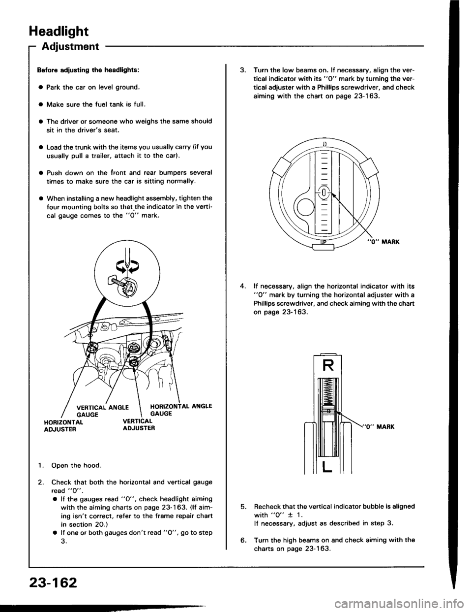
four mounting bolts so that.the indicator in the verti-
cal gauge comes to the "O" mark.
1. Open the hood.
2. Check that both the horizontal and vertical gauge
read " O" .
. lf the gauges rcad "O", check headlight aiming
with the aiming charts on page 23-163. (lf aim-
ing isn't correct, refer to the trame repair chart
in section 20.)
a lf one o. both gauges don't read "O". go to step
23-162
3. Turn the low beams on. lJ necessary, align the ver-
tical indicator with its "O" mark by turning the ver-
tical adiuster with a Phillips screwdriver, and check
aiming with the chart on page 23-163.
lf necessary, align the horizontal indicator with its"0" mark by turning the horizontal adjuster with a
Phillips screwdriver, and check aiming with the chart
on page 23-163.
4.
5.Recheck that the vertical indicator bubble is aligned
with "o" 1 1.
lf necsssary, adjust as described in step 3.
Turn the high beams on and check aiming with the
charts on page 23-163.
Page 1270 of 1413
Headlight
Headlight Replacement
1. Remove the front bumoer.
Remove the mounting bolts, then pullout the head-
light, and disconnect the connectors from it.
Afte. replacement. the horizontal and vertical aim-ing must be checked using conventional methods,
Use the aiming charts on page 23-163.
Bulb Replacement
CAUTION:
a Halogon headlights can bocomo voly hot in usa; do
not touc$ them or tho attaching hardware imm6diatoly
arter they hava been lurnod off,a Do not try to roplace or cl6an the headlights with thelights on.
I . Oisconnect the 2-P connector(s) from the headlight.
coNlrtEcToR
2. Turn the bulb(s) counterclockwise and remove the
bulb(s).
FRONT BUMP€R
HEADLIGHT
23-164
Page 1277 of 1413

Controller Input Test
NOTE: 8e careful not to damage the controller and the
instrument panal.
1. Remove the instrument panel lrom the dsshboard
{see page 23-1181.
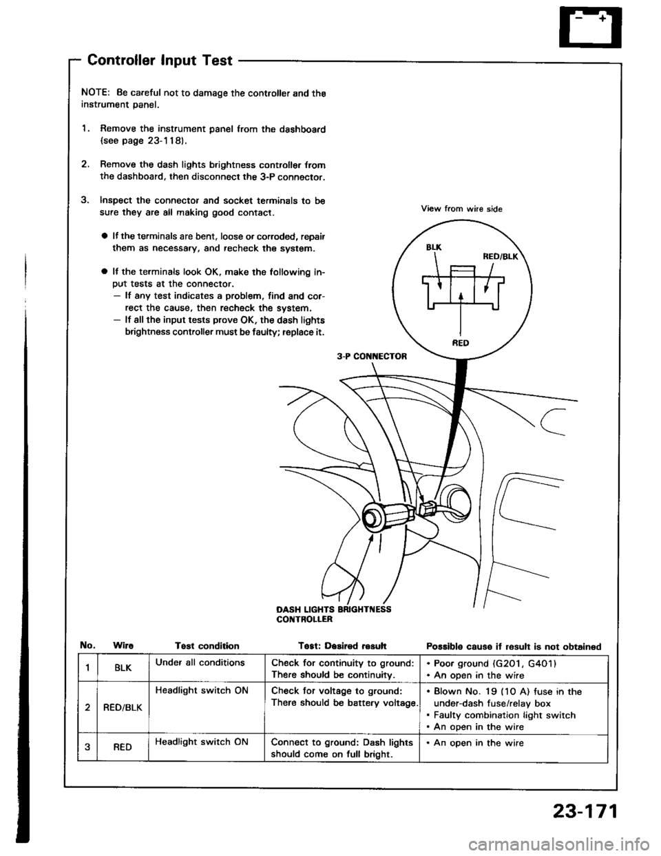
2. Remove the dash lights b.ightness controller {rom
the dashboard. then disconnect the 3-P connector.
Inspect the connector and socket terminals to be
sure they are all making good contact.
a lf the terminals are bent. loose o. corroded, repsir
them as necessary, and recheck the system.
a It the terminals look OK, make the tollowing in-
Dut tests at the connector.- lf any test indicates a problem, find and cor-
rect the cause, then recheck the system.- lf all the input tests prove OK, the dash lights
brightness controller must be faulty; replace it.
View from whe side
Possible causo it resull is not obtained
3-P CON[{ECTOR
OASH LIGHTSCOI{TROLIER
WireTost conditionTogt: Dasired resuh
1BLKUnder all conditionsCheck for continuity to ground:
There should be continuitv.
. Poor ground (G20 l , G4O1). An open in the wire
RED/BLK
Headlight switch ONCheck Jor voltage to ground:
There should be battery voltage.
Blown No. 19 (1O A) tuse in the
under-dash fuse/relay box
Faulty combination light switch
An open in the wire
aREDHeadlight switch ONConnect to ground: Dash lights
should come on full bright.
. An open in the wire
23-171
Page 1278 of 1413
Ceiling/Trunk/Gargo Area Lights, Spotlights
Component Location Index
23-172
r 1: Sedanr2: Hatchback
CEIIING LIGHTTest/Replac€mont. page 23-175
SPOTLIGHTSTest/Rsplscement, page 23-1 7 4
.1 LEFT REARDOOR SWTCHTest. page 23-150
FRONTPASSEl{GER'SDOORswtTcHTest, pago 23-150
*2 HATCH LATCHswtTcHTest/Replacement,page 23-178
11 RrcHT BEARDOOR SWrCHTost. page 23-150
11 TRUNK LATCHSWITCH '1 TRUI{K LIGHTTest/Replac€ment, Test/Replacemontpage 23-178 Page 23-177
rII-
Page 1290 of 1413
Side Marker/TurnSignal/Hazard Flasher System
Component LocationIndex
23-184
GAUTION:
a All SRS electrical wiring harnessos ar6 covered with
yellow insulation.
a Belor€ disconnocting any pan of the SRS wire har-
ngss, connoct the short connector{s).
a Rsplace tho 6ntir€ affect€d SRS harnoss sssembly il
it has an op€n cilcuit or damaged widng.
TURN SIGNAL INDICATOR LIGHTS(ln the gauge assembly)
SRS MAIN HARI{ESS(Cov.rod with Ysllow in3ulationl
Bulb Locations,23-115
COMBINATION LIGHT SWITCHReplacement, page 23-160HAZARD WARI{ING SWITCHReplacement, page 23-187Test, page 23-187
Test, page 23-1
UNDER-DASHFUSE/RELAY 8OX
TURN SIGNAL/HAZARO RELAYInput Test, page 23-186
-
Page 1294 of 1413

Stereo Sound System
Component Location Index
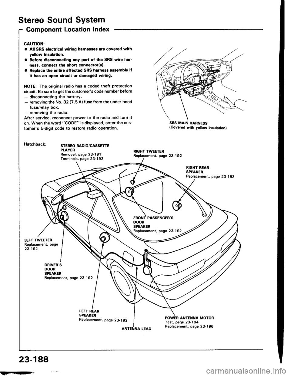
LEFT TWEETERReplacement, page
23-192
DRIVER'SDOORSPEAKERRepfacement, page 23-192
CAUTION:
a All SRS el€ctrical wlring harneaseE are covered with
yallow insulation.
a Belore dbconnscting any part of the SRS wire har-
nass, connect tho short connector(sl.
a Replace tho entir6 affoctod SRS harn6ss assembly if
it has an opan circuit or damag6d widng.
NOTE: The original radio has a coded theft protection
circuit. Be sure to get the customet's code number belore- disconnecting the battery.- removing th€ No. 32 (7.5 A)tuse from the under-hood
fuse/relay box.- removing the radio.
After service, reconn€ct power to th€ radio and tutn it
on. When the word "CODE" is displaved, enter the cus-
tomer's 5-digit code to restore radio opelation.
Hatchback:STEBEO RADIO/CASSETTEPTAYERRemoval. paoe 23-191Terminals, page 23-192
SBS MAII{ I{ARI{ESS(Covor€d wirh y6llow in3ulationl
LEFTSPEAKER
RIGHT REARSPEAKERReplacement. page 23-193
ANTENNA MOTORTest, page 23-194
DOORSPEAKERRepfacement, page 23-192
23-188
!iltil;s'
Replacemenr. page 23-193
Replacement, page 23-196
Page 1295 of 1413
Soden:
i FIGHT TWEETERReplacement, page 23-192STEREO RADIO/CASSETTEPLAYERR€moval, paoe 23-191T€rminals. page 23-192
*: USAFBONT PASSENGER'SDOORSPEAKERReplacement, page 23-192
RIGHT REARSP€AKERReplacement, page23-193
DRIVER'SDOOBSPEAKERRepfacement, p8ge 23-192
POWER ANTENNA MOTORTest, page 23-194Replacement, page 23-196
23-189
Page 1297 of 1413

Unit Removal
CAUTION:
a All SRS oloctrical wi ng harn.$.s ara covcrrd withyellow insulation.
a B€toro disconnocting any part ot tho SRS wirc hrr-
nosa, connsct tho short conn6ctol(rl.
a Raplaco the sntirs sttoctod SRS hamoas asacmbly it
it has an opon circuil 01 damagod widng.
NOTE: The original radio has a coded theft protection
circuit. Be sure to get the customer's code number b€lore- disconnecting the battery.- removing the No. 32 (7.5 A) fuse in the under-hood
fuse/relay box.- removing the radio.
After ssrvice, reconnect power to the radio and turn it on.
When the word "CODE" is displayed, enter the cus-
tomer's 5-digit code to restore radio operation.
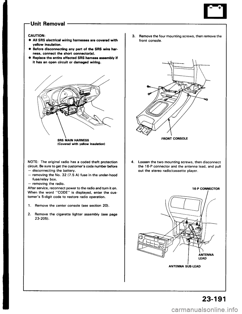
1. Remove the center console (see section 2O).
2, Remove the cigarette lighter assembly {see page
23-205t.
SRS MAII{ HABNESSFRONT CONSOLE
3.Remove the four mounting screws, then remove the
front console.
Loosen the two mounting screws, then disconnect
the 16-P connector and the antenna lead, and oull
out the stereo .adio/cassette player.
4.
16-P COi{i{ECTOR
ANTENlTA SUB-LEAD
23-191