Page 1229 of 1413

Fuel Gauge
Gauge Test
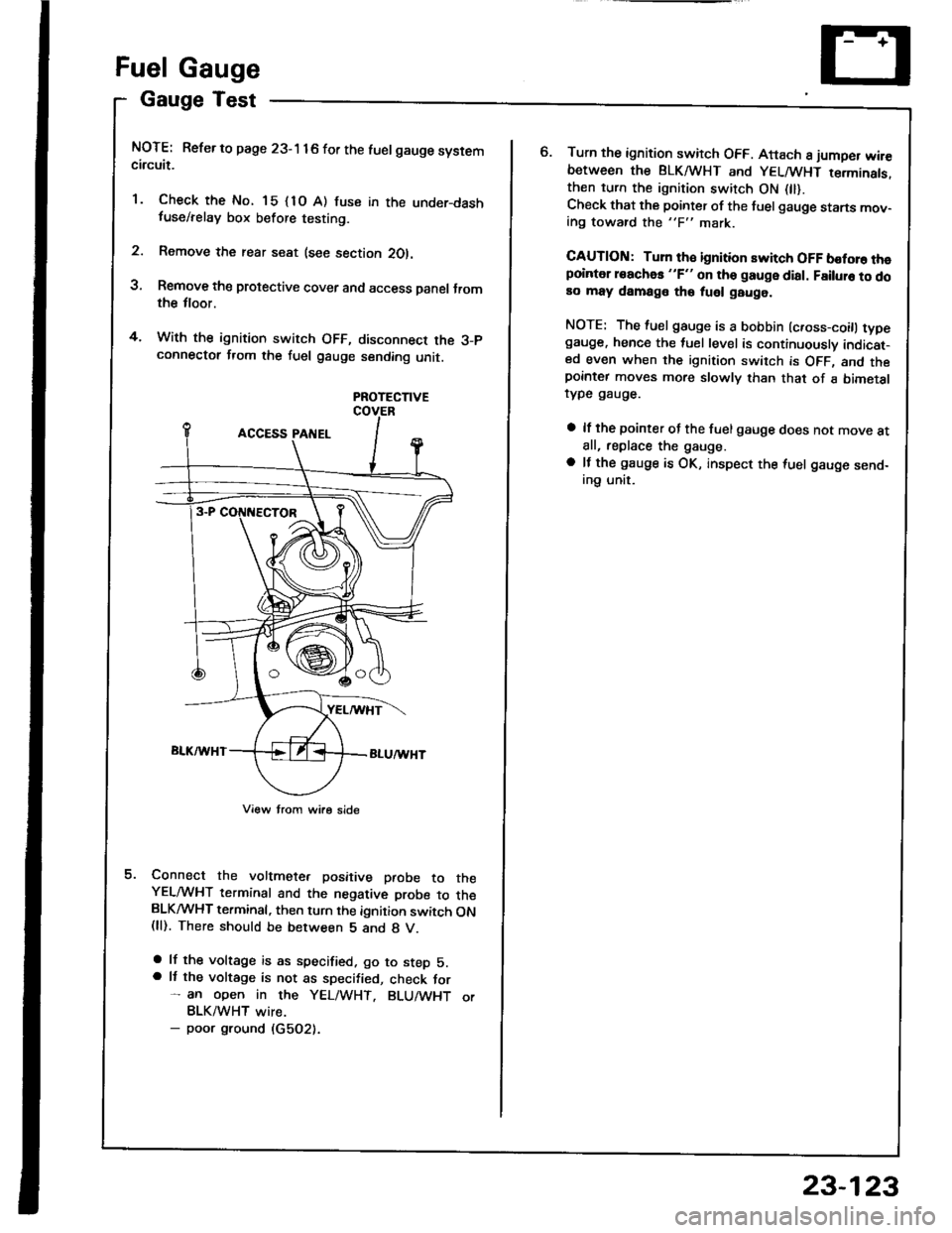
NOTE: Refer to page 23-1 16 for the luelgauge systemcircuit.
'1. Check the No. 15 {1O A) fuse in the under-dashfuse/relay box before testing.
2. Remove the rear seat (see section 2Ol.
3, Remove the protective cover and access Danel Jromthe tloor.
4. With the ignition switch OFF, disconnect the 3-pconnectot from the fuel gauge sending unit.
PROTECTIVE
Connect the voltmete. positive paobe to theYELMHT terminal and the negative probe to theBLKMHT terminal, then turn the ignition switch ON(ll). There should be between 5 and 8 V.
a lf the voltage is as specified. go to step 5.a It the voltage is not as specified, check for- an open in the YEL/WHT. BLU/WHT orBLK/WHT wire.- poor ground (G5O2).
o.Turn the ignition switch OFF. Attach 8 jumper wir€between the BLKA HT and YELMHT terminats.then turn the ignition switch ON 0l).Check that the pointer of the fuel gauge starts mov-ing toward the "F" mark.
CAUTION: Turn th€ ignition switch OFF boforo thepointer roachas "F" on tho gauge dial. Failuro to doao may damage tho fuel gauge.
NOTE: The fuel gauge is a bobbin (c.oss-coitl typegauge. hence the tuel level is continuously indicat-ed even when the ignition switch is OFF, and thepornter moves more slowly than that of a bimetalrype gauge.
a lf the pointer of the fuel gauge does not move atall, replace the gauge.
a lf the gauge is OK, inspect the {uel gauge send-ing unit.
23-123
Page 1231 of 1413

Low FuelIndicator
IndicatorLight Test
Seat Belt Reminder
System
Seat Belt Switch Test
J.
NOTE: Reter to page 23- 1 1 6 tor the wiring description
of the low fuel indicator circuit.
1. Park car on level ground.
@ oo not rmoko whil6 working on th€
fuol system, Keop op€n llamg3 awsy from your work
area. Drain fuel only into an approvod container,
Drain tuel into an 8pplov€d container. Then install
the drain bolt with a new washer.
Add less than 8.2 t (2.2 U.S.Gal, 1.8 lmp.Gal) of fuel
and turn the ignition switch ON (ll). The low fuel in-
dicator light should com€ on within lour minutes,
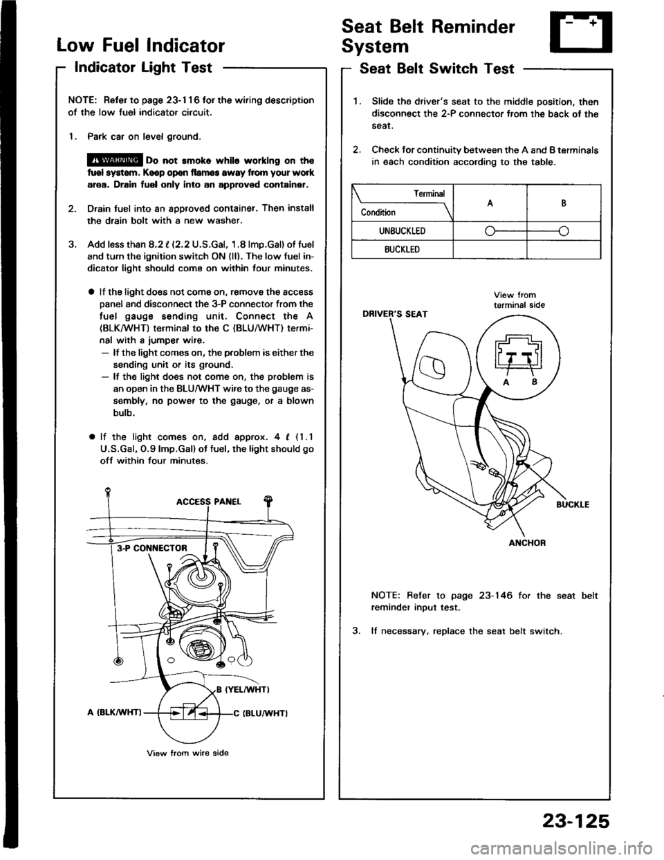
a lf the light does not come on, remove the access
Danel and disconnect the 3-P connector from the
fuel gauge sending unit, Connect the A
(BLKMHT) terminal to the C (BLU/WHT) termi-
nal with a iumper wir€.- lf the light comes on, the problem is either the
sending unit or its ground.- lf the light does not come on, the problem is
an open in the BLU/WHT wire to the gauge as-
sembly, no power to the gauge, or a blown
bulb.
a lf the light comes on, add approx. 4, {1.1
U.S.Gal, O.9lmp.Gal) ot tuel, the light should go
ofJ within four minutes.
3-P CONI{ECTOB
View lrom wire side
1.Slide the driver's seat to the middle position, then
disconnect the 2-P connector Jrom the back ot th€
sear.
Check for continuity between the A and B terminals
in each condition according to the table.
2.
NOTE: Befer to page 23-146 for the seat
reminder inout test.
3. lf necessary. replace the seat belt switch.
Terminal
C"** \AB
UNEUCKLEDo--o
BUCKLED
ANCHOR
23-125
Page 1232 of 1413

GaugeTest
NOTE: Refer to page 23-116 fot the wiring description
oJ the engine coolant temperature (ECT) gauge circuit
diagram.
1. Check the No. 15 (10 A) fuse in the under-dash
tuse/relay box before testing.
2. Make sure the ignition switch is OFF, then discon-
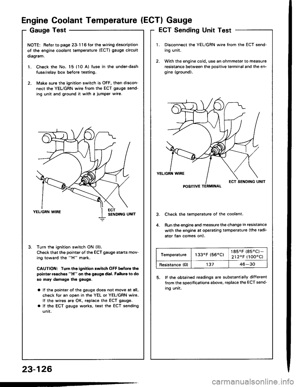
nect the YEL/GRN wire from the ECT gauge send-
ing unit and g.ound it with a jumper wire.
Turn the ignition switch ON (lll.
Check that the pointer of the ECT gauge starts mov-
ing toward the "H" mark,
CAUTION: Tuln th6 ignition switch OFF botore th€
point reaches "H" on tho gaugo dial. Failuro to do
so may damago tho gaugo.
a It the pointer of the gauge does not move at all,
check Jor an oDen in rhe YEL or YEL/GRN wire.
lf the wires are OK, replsce the ECT gauge.
a It the ECT gauge works, test the ECT sending
untt.
J.
Engine Coolant Temperature (ECTI Gauge
ECT Sending Unit Test
Disconnect the YEL/GRN wire from the ECT send-
ing unit.
With the engine cold, use an ohmmeter to measure
resistance between the positive terminal and the en-
gine (ground).
Check the temperature of the coolant.
Run the engine and measure the change in ,esistance
with the engine ai operating temperatu.e {the radi-
ator tan comes on).
5. ll the obtained readings are substantially different
Jrom the specifications above, replace the ECT send-
ing unit.
23-126
POSITIVE TERMINAL
Temperatu.e1330F (560C)185.F (850C)-
2120F (1000c)
Resistance (O)'t3746-30
Page 1233 of 1413
Brake System lndicator
Parking Brake Switch Test
Remove the tloor console, and disconnect the con-
nector from the switch.
Check for continuity b€tween the positive terminal
and body ground in each lever position accordino to
the table.
Canada:
lf the parking brake switch is OK, but ths brake sys-
tem indicator does not function, pertorm the input
test for the daytime running lights control unit (see
page 23-156).
L6vor position
TorminalPOSITIVEEODY
UP
DOWN
Brake Fluid Level Switch Test
Remove the reservoir caD.
Check that the tloat moves up and down freely, if
it does not, replace the reservoir cap sssembly.
Chsck for continuitv between the terminals in each
float position according to the table.
RESERVOIR CAPDOWN POSITION
when float drops.
4. lf necessary, replace the reservoir cap assemblv.
Terminal
Float positionPOSITIVENEGATIVE
UP
DOWN-o
POStTtVE
TERMINAL
Switch contacts open atproper fluid level.
23-127
Page 1234 of 1413
Maintenance ReminderSystem
Gomponent Location Index
23-128
CAUTION:
a All SRS eloctrical wiring haln€sses are coveled with
y€llow insulation.
a Bsfore disconnocting any part of the SRS wire har-
ne6a, connect tho shon connoctor(s).
a Replace the entire affoctod SRS hsrness ass6mbly if
it has an open circuil or damag€d wiring.
MAINTENAf{CE REMINDER LIGHT(ln th6 gaugo 63.smblylGauge Assembly. page 23-113
VEHICLE SPEED SENSOR {VSS){On the t.ansmirsion houainglTest, page 23-120, 121Input Test, page 23-120Repfacement, page 23-122
MAINTENANCE REMINDER UNITlBohind tho dashboard lowor covor)Input Test, page 23-131
MAINT
REOD
Page 1238 of 1413
A/T Gear PositionIndicator
Component Locationlndex
23-132
cAUTtOt{:
a All SRS olectdcal wiring harnossos a16 covarod with
yellow insulation.
Boforo disconnocting any part ot the SRS wlr. har-
noaa, conngct the short conn6ctor(sl.
Roplaco tho entire aff6ct6d SRS harn$s assombly il
it has an op6n cilcuit or damagod wiling,
SRS MAIN HARI{ESS(Cov.rod whh ygllow io.ul.tlonl
GAUGE ASSEMBLYBemoval, page 23-1 18Disassombly, pag€ 23'1 19Bulb Locations, pago 23-1 15IiIIERLOCK SYSTEMDGscription. page 23-139
A/T GEAR POSITIONIlTDICATORInput Test, pago 23-134
A/T GEAR P('SITIOI{ SWITCHTest, page 23-136ReDlacement, 6ection 14
Page 1240 of 1413
A/T Gear Position Indicator
Indicator Input Test
CAUTION:
a All SRS electrical widng harn6ssos ara cov6r6d whh
yellow insulation.
a Before disconnecting any part ot the SRS wiro hEr-
ness. connect the shon connoctolls).
a Replace the entire affectod SRS harnosr assombly il
it has an op€n circuit or damaged wiring.
Remove the gauge assembly from the dashboard (see
page 23- l 1 8), and disconnect connectors "8", "C" and"D" from it. lnsoect the connecto. terminals to be sure
they are all making good contact.
a lf the terminals are bent. loose or corroded, repair them
as necessary, and recheck the system.
a lf the terminals look OK, make the following input tests
at the connector.- lf any test indicates a problem, find and corect the
cause, then recheck the system.- lf all the input tests prove OK, the gauge assem-
bly must be taulty; replace it.
CONI{ECTOR "8"
SS
23-134
Page 1242 of 1413
A/T GearPosition Indicator
A/T GeaPosition Switch Test
23-136
1.
2.
I I gear Fosluon Dwtrcn I esr -
Remove the console. then disconnect the 14-P con-
nector from the switch.
Check for continuitv between the terminals in each
position according to the table.
a Move the lever back and forth at each position
without touching the push button, and check tor
continuity within the range of free play.
a lf there is no continuity within the.ange of free
play, adjust the installing position ol the switch
as described on the next page.
A/T Goar Position Swhch (Without crulso contloll
A/T Goar Position Switch (With cruiss controll
tgrminal90e
14-P CONI{ECTOR
Back-up Noutrrl
Ught Swhch Polition Swhch
Back-up t{outral
Llght Swltch Potidon Swltch
Terminal
P*ii-_\BFNMDK
tro-
ao---o
Eo---o
Eo-
No--.oo-
tro--oo---o
tro---oo---o
Terminal
P*,i-
_\6NMDJK
tro---o
ao---.o
Eo---o
E--o
EG_o-
Eo-o---o
Eo---oo---o