Page 242 of 1413

PGM-FI System
rj-t
--t-.
Fuel Supply System
-+-lt@t- -t 13 |- ' "- - --i--
T,-n The Maltunction Indicator Lamp (MlL) indicares Diagnostic Trouble Code (DTC) 43: A problem in
- L:!-i - the Heated Oxygen Sensor (HO2S) circuit. or a probtem in the Fuel Supply System.
NOTE:. Use DIGITAL MULTIMETER.. U6e 2 Volt rang6.
o oooooo oooooo I oo oooooooooooooooooooQoo ooo ooooo I oooo ooooooooooooooo
426
JUMPER WIRE
o ooooo oooo ooo I oo oooooo Isdtcllodsl ooo ooooooooo oooo ooo oo ooo I oooo ooooooooooooooo
D14 {+l
I
426 t-l vohrgo rhould rl.n.t
| 0.4-0.5 V wh.n th..- ignirioo .wilch i! firdt|rtrod o.r, Itd docr!6ato b.low O.1 V in L..th6n two minutaa.
- Tho MIL h.s boen reportod on.- With rhe SCS short con-noctor connocted (soo paga1l-34), codo 43 b indlcat.d,
From codr I troebl.-lhoorlng lprgo 1146).
ls the code 43 accompanied bythe MIL and poor driveability?Go to Fuol Supply .y.t.m (|ecpag6 1t-971.
Do the ECM Reset ftocedure lseepage 11-35).
Connect the SCS short connectorto the service check connector{see page 'l1-34).
Start the engine. Hold the engineat 3,00O rDm with no load {A/T in
@or@ position, M/T in neutral)until the radiator Ian comes on,then let it idle for at least onemanute,
Intonnitl.nt t llure, tydom lr OKat thi. tim. lto.t drlv. mly b.nocaararyr.Chock lor poo? connactlona otloots wiro at C223 lloc.t.d atrlghl lhock towo.]. Cl13lHO2Sland ECM,
Raise the engine speed to 3,000rpm and hold that throttle positiontor at least one minute.Do not vary the throttle positioneven if the rpm drops.
Ooes the MIL blink and does itindicate code 43?
Turn the ignition swilch OFF.
Connect the test harness betweenthe ECM and conneclors {seepage 1 1-371.
With the ignition switch OFF, waitfor at least two minutes.
lnstall a jumper wire on the testharness between A6 and A26.
11-50
1To page 1 1-5'l l
Page 1182 of 1413

Starting System
Startel Test
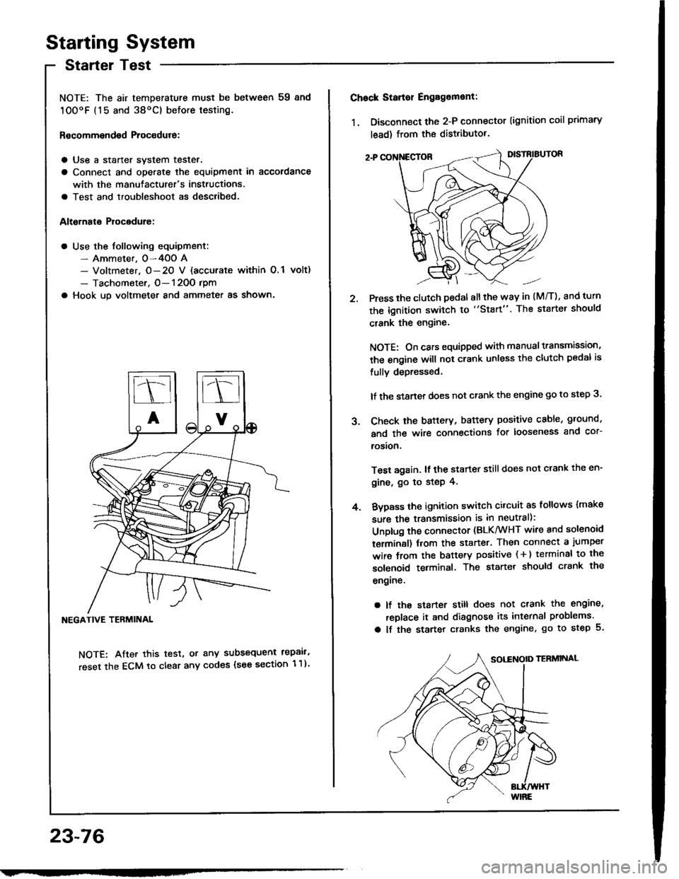
NOTE: The air temDerature must be between 59 8nd
10OoF (15 and 38oC) before testing.
Recommendsd Procodure:
a Use a staner svstem tester.
a Connect and operate the equipment in accordance
with the manutacturer's instructions.
a Test and troubleshoot as described.
Altohato Procedure:
a Use the following equipment:- Ammeter. 0-4OO A- Voltmeter, O- 20 V {accurate within 0.1 volt)
- Tachometer, O- 120O rpm
a Hook up voltmeter and ammeter as shown'
NEGATIVE TERMINAL
NOTE: After this test, or any subsequent repair,
reset the ECM to clear any codes (see section 1 1)
23-76
2.
Chock Stan€r Engag6ment:
1. Disconnect the 2-P connector (ignition coil primary
lead) from the distributor.
Press the clutch pedal allthe way in (M/T), and turn
the ignition switch to "Start". The starter should
crank the engine.
NOTE: On cars equipped with manual transmission,
the engine will not crank unless the clutch pedal is
fully depressed.
lf the staner does not crank the engine go to step 3.
Check the baftery, battery positive cable, ground,
and the wire connections for looseness and cor-
rosion,
Test again. lf the starter still does not crank the en-
gine, go to step 4.
Bvpass the ignition switch citcuit as follows {make
sure the transmission is in neutral):
Unplug the connector (BLK/WHT wire and solenoid
terminsl) trom the starter. Then connect a jumper
wire from the battery positive ( + ) terminal to the
solenoid terminal. The starter should crank the
engrne.
a lf the starter still does not crank the engine,
replace it and diagnose its internal problems.
a lf the starter cranks the engine, go to step 5.
J.
4.
Page 1195 of 1413
lgnition Timing Inspection and Setting
1.Start the engine. Hold the engine at 3,00O rpm with
no load (A/T in S or E position, M/T in neutral) until
the radiator fan comes on, then let it idle.
Pull out the service check connector located behind
the right kick panel. Connect the BRN/WHT and BLK
terminals with the SCS short connector.
4. Adiust ignition timing, if necessary, to the follow-
ing specifications:
lgnition Timing:
16 t 2 BTDC (RED) at 75O 1 50 rpm in noutral
NOTE:
a Shift lever must be in neutral.
a All electrical systems should be turned OFF.DATA LINKCONNECTOR {3-P}NOTE: Do not attachthe jumper wire.
POINTER
SCS SHORT CONNECTOR{0?PAZ-O010't 00t
SERVICE CHECK CONNECTOR I2.PINOTE: Located behind the right kickoanel
Connect a timing light to the No.1 ignition wire andpoint it toward the pointer on the timing belt cover.
TIMING LIGHT
lcont'd)
REO MARK
23-89
Page 1229 of 1413

Fuel Gauge
Gauge Test
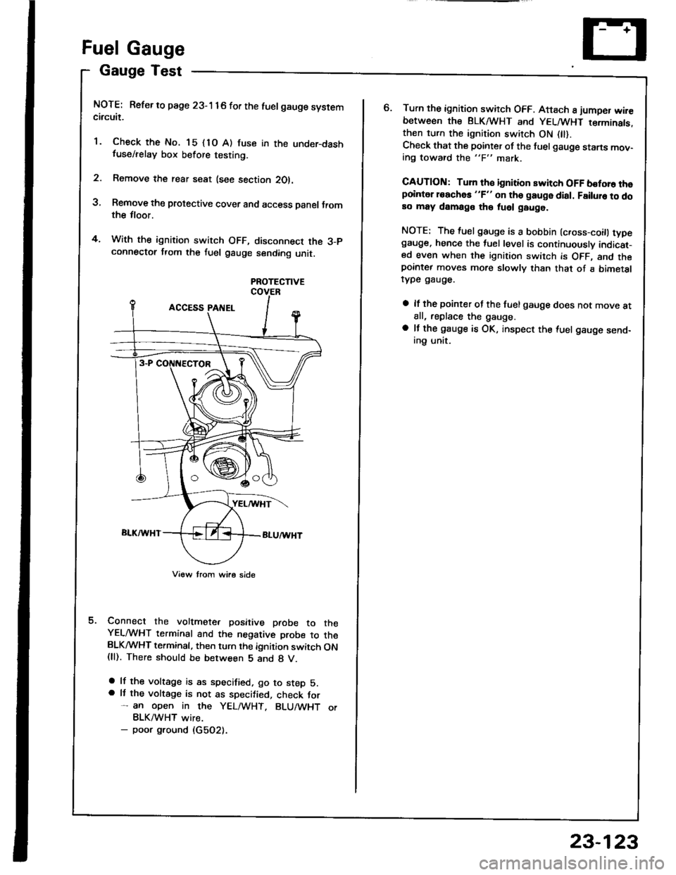
NOTE: Refer to page 23-1 16 for the luelgauge systemcircuit.
'1. Check the No. 15 {1O A) fuse in the under-dashfuse/relay box before testing.
2. Remove the rear seat (see section 2Ol.
3, Remove the protective cover and access Danel Jromthe tloor.
4. With the ignition switch OFF, disconnect the 3-pconnectot from the fuel gauge sending unit.
PROTECTIVE
Connect the voltmete. positive paobe to theYELMHT terminal and the negative probe to theBLKMHT terminal, then turn the ignition switch ON(ll). There should be between 5 and 8 V.
a lf the voltage is as specified. go to step 5.a It the voltage is not as specified, check for- an open in the YEL/WHT. BLU/WHT orBLK/WHT wire.- poor ground (G5O2).
o.Turn the ignition switch OFF. Attach 8 jumper wir€between the BLKA HT and YELMHT terminats.then turn the ignition switch ON 0l).Check that the pointer of the fuel gauge starts mov-ing toward the "F" mark.
CAUTION: Turn th€ ignition switch OFF boforo thepointer roachas "F" on tho gauge dial. Failuro to doao may damage tho fuel gauge.
NOTE: The fuel gauge is a bobbin (c.oss-coitl typegauge. hence the tuel level is continuously indicat-ed even when the ignition switch is OFF, and thepornter moves more slowly than that of a bimetalrype gauge.
a lf the pointer of the fuel gauge does not move atall, replace the gauge.
a lf the gauge is OK, inspect the {uel gauge send-ing unit.
23-123
Page 1232 of 1413

GaugeTest
NOTE: Refer to page 23-116 fot the wiring description
oJ the engine coolant temperature (ECT) gauge circuit
diagram.
1. Check the No. 15 (10 A) fuse in the under-dash
tuse/relay box before testing.
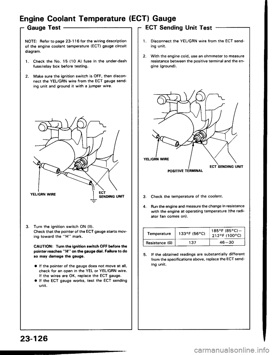
2. Make sure the ignition switch is OFF, then discon-
nect the YEL/GRN wire from the ECT gauge send-
ing unit and g.ound it with a jumper wire.
Turn the ignition switch ON (lll.
Check that the pointer of the ECT gauge starts mov-
ing toward the "H" mark,
CAUTION: Tuln th6 ignition switch OFF botore th€
point reaches "H" on tho gaugo dial. Failuro to do
so may damago tho gaugo.
a It the pointer of the gauge does not move at all,
check Jor an oDen in rhe YEL or YEL/GRN wire.
lf the wires are OK, replsce the ECT gauge.
a It the ECT gauge works, test the ECT sending
untt.
J.
Engine Coolant Temperature (ECTI Gauge
ECT Sending Unit Test
Disconnect the YEL/GRN wire from the ECT send-
ing unit.
With the engine cold, use an ohmmeter to measure
resistance between the positive terminal and the en-
gine (ground).
Check the temperature of the coolant.
Run the engine and measure the change in ,esistance
with the engine ai operating temperatu.e {the radi-
ator tan comes on).
5. ll the obtained readings are substantially different
Jrom the specifications above, replace the ECT send-
ing unit.
23-126
POSITIVE TERMINAL
Temperatu.e1330F (560C)185.F (850C)-
2120F (1000c)
Resistance (O)'t3746-30