Page 1136 of 1413

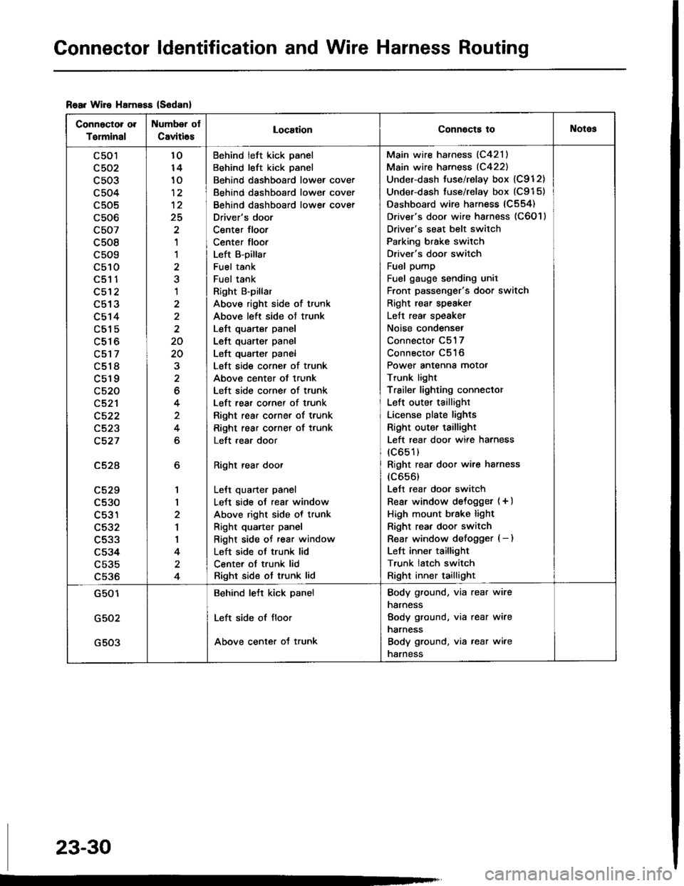
Connector ldentification and Wire Harness Routing
Rear Wire HamsEs (S6danl
Connector ol
Torminal
Number ot
Caviti6sLocaiionConnocts toNotos
c501
c503
c504
c505
c506
c507
c508
c509
c510aEt t
c512
L9 IJ
c514
c515
c516
c517
c518
c519
c520
c521
c522
c523
c527
c52A
LCZY
c530
c531
c532
c533
c534
c535
c536
6
1,|
2
1
I
4
4
10
10
12
25
'I
1
a
1
2
2
20
20
2
6
4
4
6
Behind left kick panel
Behind left kick panel
Behind dashboard lower cover
Behind dashboard lower cover
Behind dashboard lowe, cover
Driver's door
Center floor
Center floor
Left B-pillar
Fuel tank
Fuel tank
Right B'pillar
Above right side of trunk
Above left side ot trunk
Left quarter panel
Left quarter panel
Left quarter panel
Left side corner of trunk
Above center of trunk
Left side corner of trunk
Left rear corner of trunk
Right rear corner of trunk
Right rear corner of trunk
Left ,ear door
Right rear door
LeJt quarter panel
LeJt side oJ rear window
Above right side of trunk
Right quarter panel
Right side of rear window
Left side ot trunk lid
Center ot trunk lid
Right side ot trunk lid
Main wire harness (C421)
Main wire harness (C422)
Under-dash tuse/relay box {C912}
Under-dash fuse/relay box (C915)
Dashboard wire harness (C554)
Driver's door wire harness (C6O l )
Driver's seat belt switch
Parking brake switch
Driver's door switch
Fuel pump
Fuel gauge sending unil
Front passenger's door switch
Right rear speaker
Left rear speaker
Noise condenser
Connector C517
Connector C516
Power antenna motor
Trunk light
Trailer lighting conneclor
Left outer taillighr
License plate lights
Right outer taillighr
Left rear door wire harness
(c651)
Right rear door wire harness
(c656)
Lett rear door switch
Rear window delogget (+ )
High mount btake light
Right rear door switch
Rear window defogger (- )
Left inner taillight
T,unk latch switch
Right inner taillight
G501
G502
G503
Behind lett kick panel
Left side of floor
Above center of trunk
Body ground, via rear wire
narness
Body ground, via rear wire
narness
Body ground, via rear wire
narness
23-30
Page 1140 of 1413
Connector ldentification and Wire Harness Routing
Drlvar's Door Wir6 Hamors
Connectot 01
Torminal
Number of
CavitlesLocationConnocts toNotos
c601
c602
c603
c604
c605
c605
c606
c607
c608
c609
c610
c61 1
c612
25
2
4
14
I
I
10
10
o
2
I
Driver's door
Driver's door
Driver's door
Driver's door
Behind mirror panel
Driver's door
Driver's door
Driver's door
Driv€r's door
Driver's door
Driver's door
Oriver's door
Driver's door
Oriver's door wire harness (C506)
Driver's door speaker
Driver's power window motor
Power door lock control unit
Left power mirror
Left power mirror
Lett tweeter
Driver's door lock switch
Power mirror switch
Power window master switch
D.iver's door lock actuator as-
sembly
Driver's key cylinder switch
Power window master switchSedan
Hatchback
Sedan
818C1
engrne
23-34
Page 1142 of 1413
Connector ldentification and Wire Harness Routing
Flont Pasa€ngol's Door Wire Hamosg
Conngctor or
Talminal
Numbel of
C8viti63LocatlonConnocts toNot6s
c626
c627
c628
c629
c629
c630
c631
c632
c633
c634
25
2
2
8
tt
2
5
2
Front passenger's door
Front passsngel'�s door
Front pssseng€r's door
Behind cover panel
Front passenger's door
Front passengor's door
Front passenger's door
Front Passonger's dool
Front passeng€r's door
Front pass€ngot's door
Main wire harness (C4O1)
Front passenger's door speaker
Front passeng€r's power window
motot
Right power mirror
Right power mirror
Right tweeler
Front passenger's door lock
switch
Front passengor's Power window
switch
Front passenget's door lock ac-
tuator
Front passengor's door key
cylind6r switch
Hatchback
S6dan
818C 1
6n9ino
23-36
Page 1298 of 1413
![HONDA INTEGRA 1994 4.G Workshop Manual Terminals
Connects to
\
*i,.,-terlll
FO] ANTENNA LEADA
TI!NM[IAL
A9---------+A16
Stereo Sound System
Stereo Radio/Cassette PlayerFront Speaker/Tweeter
Replacement
Front Spoakor:
1. Carefully pry out t HONDA INTEGRA 1994 4.G Workshop Manual Terminals
Connects to
\
*i,.,-terlll
FO] ANTENNA LEADA
TI!NM[IAL
A9---------+A16
Stereo Sound System
Stereo Radio/Cassette PlayerFront Speaker/Tweeter
Replacement
Front Spoakor:
1. Carefully pry out t](/manual-img/13/6067/w960_6067-1297.png)
Terminals
Connects to
\
*i,.,-terlll
FO] ANTENNA LEADA
TI!NM[IAL
A9---------+A16
Stereo Sound System
Stereo Radio/Cassette PlayerFront Speaker/Tweeter
Replacement
Front Spoakor:
1. Carefully pry out the speaker cover.
2. Remove the three screws, then disconnect the 2-P
connector Jrom the speaker, and remove the
speaker.
2.P CONNECTOR
Twootor:
1. Remove the door panel and disconnect the tweeter
2-P connector.
2. Remove the two screws, then remove the tweeter
ano covet.
r^l
It
\7
rSPEAKERCOVER
A1RED/GRNFront passenger's door speaker O
A2BLU/GRNDriver's door speaker @
A3RED/BLKLights-on signal
A4WHT/8LUConstant power {Tuning memory)
A5YEL/REDACC (Main stereo powe. supplyl
A6YEL/GRNRadio switched power (To antenna)
A7BLU/YELLeft rear speaker O
A8RED/YELRight rear speaker @
A9BRN/BLKFront passenger's door speaker O
A10GRY/BLKDriver's door speaker O
A lnot used)
412(not used)
A13(not usedl
A14BLKGround (G551)
Al5GRY/WHTLeft rear speaker O
A16BRNAA/HTRight rear speaker e
23-192
IFrIFit
Page 1324 of 1413
Power Mirrors
Switch Test
Remove the driver's door panel (see section 2O).
Check tor continuitv between the terminals in each
switch position according to the table.
Mirror Switch
rermrnal
Position \J
R
OFFG"
UP
-o
o--<>-
DOWN
-o
o--o
LEFTo-
-o
RIGHT
-o
o-
OFFo--o
UP
o--(J_
DOWN
-o
G--o
tEFT
-o
-o
RIGHTG-
P-o
23-214
aaaaaaaa
A-------+J
Page 1325 of 1413

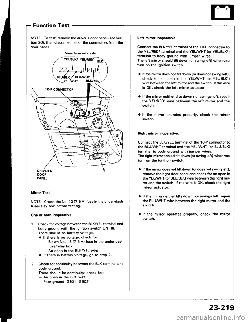
FunctionTest
NOTE: To test, remove the driver's door panel (see sec-
tion 20), then disconnect all of the connectors from the
door oanel.
Miror Tost
NOTE; Check the No. 13 (7.5 A) tuse in the under-dash
fuse/relay box before testing.
Ono or both inop€rativa:
1. Check for voltage between the BLKIrEL terminal 8nd
body ground with the ignition switch ON (ll).
There should be battery voltage.
a lf there is no voltage, check tor:- Blown No. 13 {7.5 A) fuse in the under-dash
fuse/relav box- An ooen in the BLK/YEL wire
a It there is battery voltage, go to step 2.
2. Check for continuity between the BLK terminal and
body ground.
There should be continuity; check Jor:- An ooen in the BLK wire- Poor ground (G501, G5O2)
View from wire side
Loft mirror inopsrative:
Connect the BLK/YEL terminal of the 10-P connector to
the YEL/RED1 terminal and the YEL/WHT (or YEL/BLKr)
terminal to body ground with jumper wires.
The left mirror should tilt down (or swing leftl when you
turn on the ignition switch.
a lf the mirror does not tilt down (or does not swing leftl,
check Jor an open in the YEL/WHT (or YEL/BLK1)
wire between the left miffor and the switch. It the wir€
is OK, check the left mirror actuator.
a lf the mirro. neither tilts down nor swings left, repair
the YEL/RED1 wire between the left mirror and the
switch.
a lf the mirror operates properly, check the mirror
swatch.
Right mirror inoporative:
Connect the BLK/YEL terminal of the 1O-P connector to
th€ BLU/WHT terminal and the YEL/WHT {or BLU/BLK)
terminal to body ground with iumper wires.
The right mirror should tilt down (or swing left) when you
turn on the ignition switch.
a lf the mirror does not tilt down (or does not swing left),
remove the right door panel and check for an open in
the YELMHT (or BLU/BLK) wire between the right mir-
ror and the switch. lf the wire is OK. check the right
mtrror actualor.
a ll the mirror neither tilts down nor swings lelt, repair
the BLUMHT wire between the right mirror and the
switch.
a lf the mirror operates properly, check the mirror
swatch.
23-219
Page 1326 of 1413
Power
Door
Mirrors
Mirror Test
1, Remove the mirror panel and door panel (Sed8n).
then disconnect the 8-P (Hatchback) or 3-P (Sedan)
connector from the power mirror actuator.
Sedan:
MIRNOR
Hatchback:3. lf the mirror fsils to operate properly, replace it.
Check actuator operation by connecting power and
ground according to the table.
TILT:
Position
Terminal'| (H)2(G)
UP@I
DOWNtJo
SWING:
Position
Terminal2(G)3(Ft
LEFTo
RIGHT(D
23-220
Page 1327 of 1413
Power Mirror Replacement
2.
l.
t
Carefully pry out the miror panel with a llat tip
screwdriv€r.
Remove th€ door panel (see section 20).
HEtchblck:hca! hara torolalaa lha conn9clor
Disconnect the 8-P (Hatchb€ck) or 3-P (Sedan) con-
nector from thg oower mirror actuator.
While holding the mirror with one hand, remove its
mounting nuts (Hatchback) or mounting screws(Sedan) with the other.
4.
MIRROR PA]IEL
CO ECTOR
23-221