1994 HONDA INTEGRA door panel
[x] Cancel search: door panelPage 971 of 1413

Headliner
Replacement {cont'd)
5. Remove the .ool trim (moonroof modell.
6. Detach the clips by sliding the headliner forward.
A : Clip locations, 3
HEADLINER
Remove the headliner through the passenger's door
opening.
lnstallation is the reverse ot the removal procedure
NOTE:
a When inserting the headliner through the door
opening. be careful not to fold or bend it. Also,
be careful not to scratch the body
a Check that both sides ot the headliner are secure-
ly attached to the trim and Panels.
a When installing the roof trim, install the joint
toward the rear.
)
HEADLINER
20-102
Page 1031 of 1413
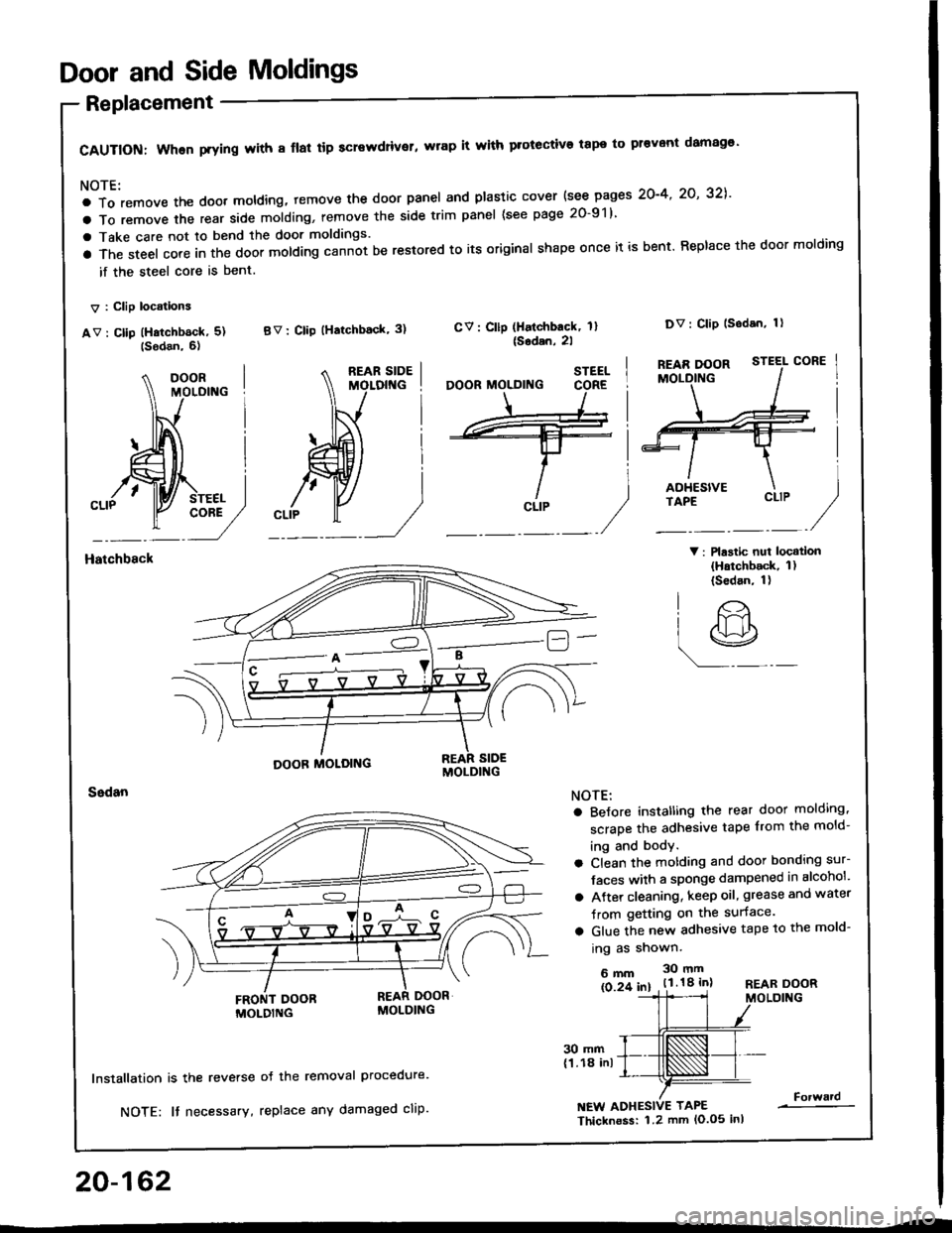
Door and Side Moldings
Replacement
CAUTION: When prying with 8 flal tip screwdriver, wrap it with protective tape to pr€vont damag€'
NOTE:
a To remove the doot moldlng, temove the door panel and plastic cover {see pages 2O-4' 2O' 32],'
a To remove the rear side molding, remove the side trim panel (see page 20-91)
a Take care not to bend the door moldings.
a The steel core in the door molding cann-ot be restored to its original shape once it is bent. Replace the door molding
if the steel core is bent.
V : Clip locations
av : cllp (Hatchb6ck, 5) BV: clip (Hatchback' 3)
V: Plastic nui locatlon(Hatchback, 1)(Sedan, 1)
CV: Cllp (Halchback, 1l{Sodan,2l
Dv: Clip lsodan, 1)
Hatchbsck
20-162
30 mm(1.18 inl
lnstallation is the reverse
NOTE: It necessary,
oJ the removal Procedure.
replace any damaged cliP.NEW ADHESIVE TAPE
Thicknoss: 1.2 mm lo.o5 inl
Forward
STEEL
CLIP
O'
lr>
r9
NOTE:
a BeJore instatling the rear door molding,
scrape the adhesive tape from the mold-
ing and body.
a Clean the motding and door bonding sur-
Jaces with a sponge dampened in alcohol'
a Atter cleaning, keep oil, grease and water
Jrom getting on the surface.
a Glue the new adhesive tape to the mold-
ing as shown.
6mm 30mm
ls 2f 61 . t.l.18 inlREAR DOORMOLDING
Page 1038 of 1413
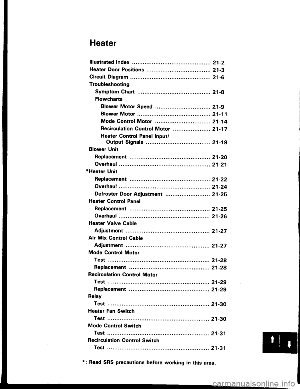
Heater
lflustrated Index ............. .........21-2
Heater Door Positions .........,..,. 21-3
Circuit Diagram ....................... 21-6
Troubleshooting
Symptom Chart ............. ......21-8
Flowcharts
Blower Motor Speed ............................... 21 -9
Bfower Motor .........,..,,,,,.. 21-11
Mode Control Moto. ............ ................... 21 -14
Recircufation Control Motor ......,...,.,,,.,.... 21 -17
Heater Control Panel Input/
Output Signals ..............21-19
Blower Unit
Repfacoment ....................... 21-20
Overhaul .......21-21
+Heater Unit
Repfacement ....................... 21-22
Overhaul .......21-24
Def roster Door Adjustment ...,............. ......,, 21 -25
Heatel Control Panel
Repfacoment ....................... 21-25
Overhaul .......21-26
Heater Valve Cable
Adjustment ...21-27
Air Mix Control Cable
Adjustment ... 21-27
Mode Control Motol
Test .............. ..................... 21-2e
Repfacement ..,..............,,,,.. 21-28
Recirculation Control Motor
Test .............. ..................... 21-29
Repfacement ....................... 21-29
Relay
Test .............. ..................... 21-30
Heater Fan Switch
Test .............. ..................... 21-30
Mode Control Switch
Test .............. ..................... 21-31
Recilculation Control Switch
Test .............. ..................... 21 -31
*: Read SRS precautions before working in this area.
Page 1055 of 1413
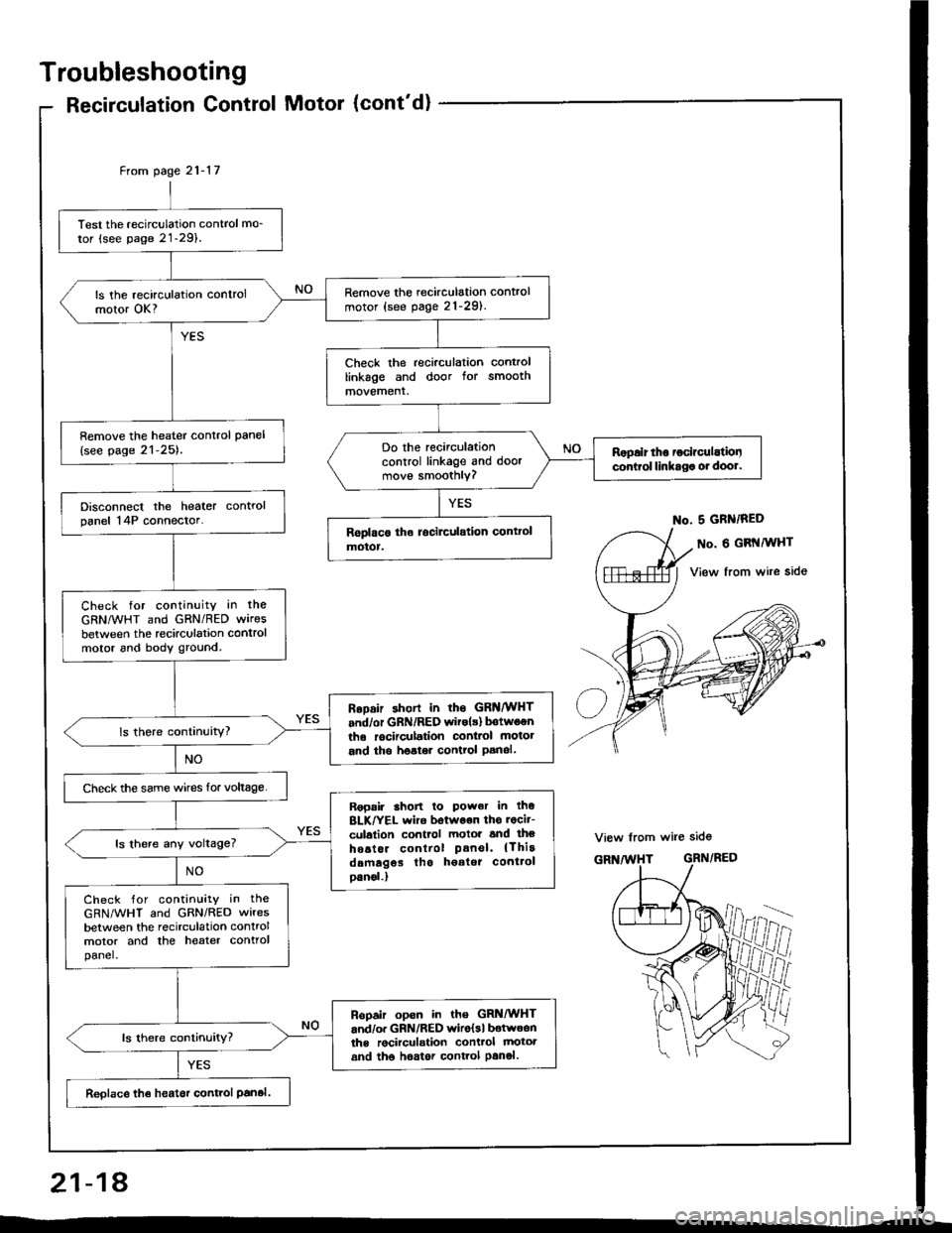
Troubleshooting
Recirculation Control Motor (cont'd)
Test the recirculation control mo_
tor (see page 21-29).
Remove the recirculation control
motor (see pag. 21-291.ls the recirculation controlmotor OK?
Check the recirculation controllinkage and door for smoothmovement.
Remove the heater control pan€l
{see page 21-25).Do the recirculationcontrol linkage and doormove smoothly?
Ropalr tho ioclrculatiooconirol linkaga ot dool.
Disconnect the heater controlpanel 14P connector.
Check for continuity in the
GRNMHT and GRN/RED wires
between the recirculation controlmotor 6nd body ground.
RoDair shorl in rhs GRNMHT
and/or GRN/RED witols) botwoenthe rocirculation conl.ol motot
and tho hoster control Panol.
Check the same wircs for voltage.
Ropair 3hon lo Power in thoBLK/YEL wiro botwoon ths rocit-
culalion control motoi and lheho6tor control Panel' {Thirddmagos tho h€atot cont.ol
oanol.)
ls there any voltage?
Check for contin!ity in the
GRN/WHT and GRN/RED wires
between the recirculation controlmotor and the heater controlpanel.
Ropair opsn in the GRi|/WHTand/o. GRN/RED wiro{sl botwoonths rocirculstion conttol mototand tho hoator control Panol.
Reolace th€ heatsr control Panal.
From page 21- l7
No. 5 GRN/RED
o. 6 GRI{MHT
View from wire side
View from wire sid6
GRN/RED
ffii
21-18
Page 1062 of 1413
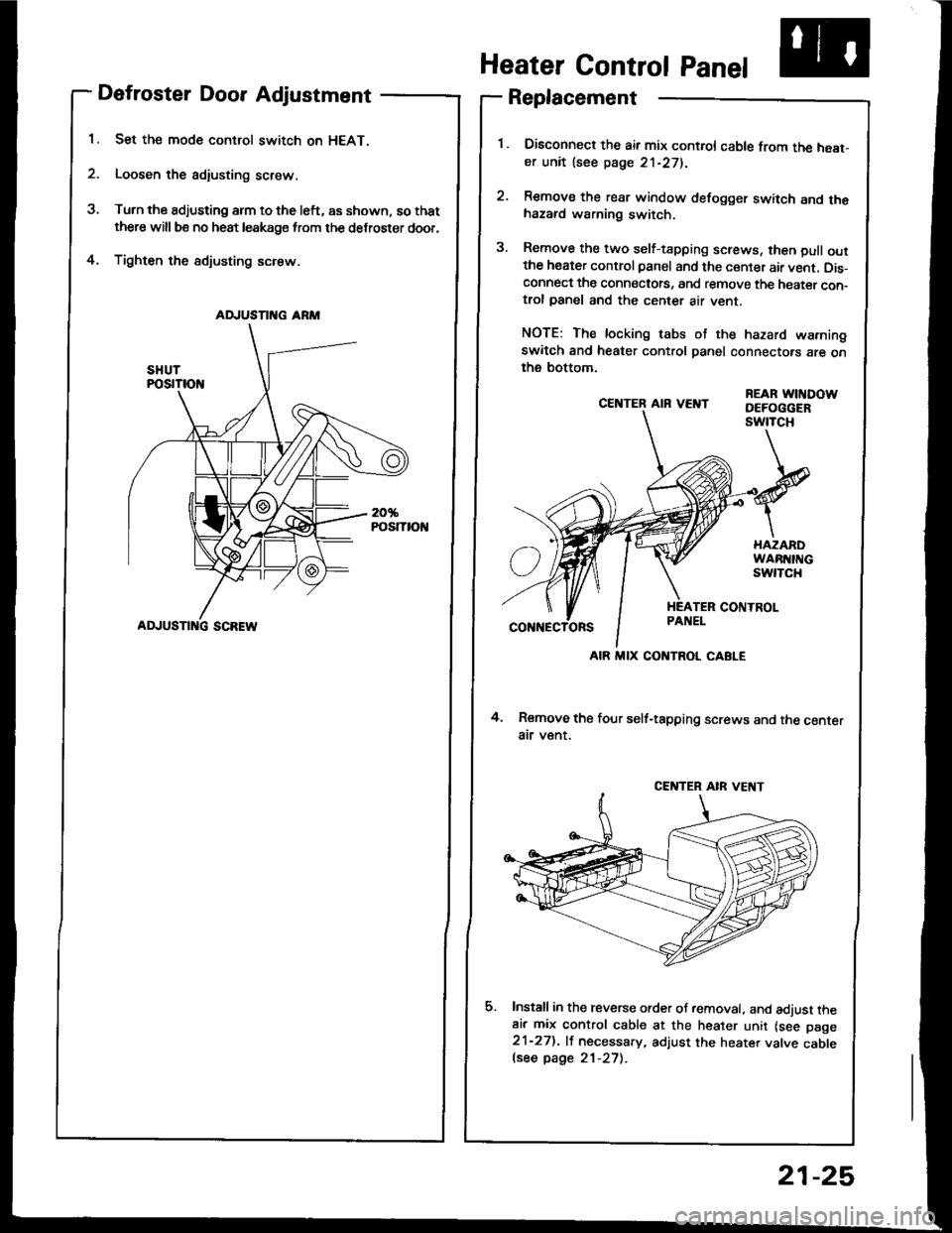
Defroster Door Adjustment
Set the mode control switch on HEAT.
Loosen the adiusting screw.
Turn the adjusting arm to the left, as shown, so that
there will be no heat leakage from the defroster door,
Tighten the sdjusting screw.4.
CE]TTER AIR VEI{T
4. Remove the four self-tapping screws and the centerair v€nt.
Install in the reverse order of removal. and adjust theair mix control cable at the heater unit lsee page21-27). lf necessary, adjust the heater valve cablelsee page 21-27).
REAR WITIDOWDEFOGGERswtTcH
Heater Control Panel
Replacement
Disconned the air mix control cable from the heat-er unit lsee page 21-271.
Remove the rear window defogger switch and thehazard warning switch.
Remove the two self-tapping screws, then pull outthe heater control panel and the center air vent. Dis-connect the connectots, and remove the heater con-trol panel and the center air vent.
NOTE: The locking tabs of the hazard warningswitch and heater control panel connectors are onthe bottom.
AD.'USTII{G ARM
ADJUSTI G SCREW
AIR MIX CONTROL CABLE
CENTEB AIR VE T
21-25
Page 1107 of 1413

Electrical
Special Tools
Troubleshooting
Tips and Precautions ................................ 23-3Five-stop Tloubleshooting ..............,...-..-... Z3-sSchematic Symbols ................................_. 23-6wire Color Cod€s ..................................... 23-6Relay and Control Unit Locations
Engine Compartment .........,............ ... --. 23-7Dsshboard and Door ..,,......................... 23-gDashboard and Floor ............................. 23-t OOuaner Panel .....-.....23-12Connector ldentification and WireHarness Routing ........ 23-i 3
Index to Circuits and Systems
Airbag ............... ...-..-... 2g-26sAir Conditioning ....,.. Section 2lAltelnator ......_.............. 23-99Anti-lock Brake Systsm (ABS) Section 19Automatic Transmission Section 14Battery .............. .......... 23-66Chafging System ........... 23-98rCigalstte Lighter .....................-...-......-..-.. Z3-2O4Cfock ................. ..........23-197rcruise Controf .......--..-... 23-242Distributor .................... 23-87Fan Controls ................. 23-1ogFuel and Emissions ... Section 1i*Fuses
Under-dash Fuse/Relay Box ................... 23-48Undor-hood ABS Fuse/Retay Box ............ 23-51Under-hood Fuse/Relay Box,.................. 23-52rGauges
Engine Coolant Temperature {ECT)Gauge ................ ..23-126Fuef cauge ............... 2g-123'Gauge Assembly ....--.23-113Speedometer .....-...,,. 23-114Tachometer .....,.....-.. 23-114Ground Distribution ........ 23-60Heater ,,,........,.... ..... Section 2lrHorn ................. ........... 23-199*fgnition Switch ............. 23-70fgnition Syst6m .......-..-.. 23-A7lgnition Timing .............. 23-89Indicator Lights"A/T Gear Position .............. ................... 23-1 32B1ak6 System ...,..,..-.23-127Engine Oil Pressura .............................. _ 23-1 51Low Fuel ............ ......23-125Malfunction Indicator Lamp {MlL} ...,,. Section I l
tfnteglated Control Unit ...29-144*lnterlock System ...................................... 23-1 3gLights, Exteriol
Back-up Lights ........... 23-179Brake Lights .............. 23-t8ltDaytime Running Lights {Csnada} ........... 23-156Front Palking Lights ............................. 23-1 65Flont Side Marker Lights ....................... 23-165Front Turn Signal Lights ........................ 23-1 65*Hazard Warning Lights .........................- 2g-1A4Headlights ................. 23-t6tLicense Plate Lights .............................. 23-1 69Taillights(Harchback) .......... 23-166
{Sedan) .............. .. 23-167Lights. Inteliol
Cargo Area Light {Hatchback) ...... -.. -.. -... 23-177Ceifing Light ........-..-.23-175
Dash Lights Blightness Controt .............. 23-t70Glove Box Lighr ................................... 23-1 69Spotfighr ............ ....-.23-174Trunk Light (Sedanl ............... .............. - 23.-177*Lighting Sysrem .......-.-... 23-152:Moonroof ,,.,.......,..,,,,,.-.23-211PGM-FI Systom ........ S€crion 11Power Distribution .,.-..--..23-54Power Door Locks .............,,..................... 23-233Power Mirors ..,..,....-...- 23-216Power Relays ...........,..... 23-68Power Windows ............ 29-222*Rear Window Defogger ........,... ..........,..... - 23-20,6Reminder Systems
Key-in Remindel System ....,.............,.... 23-1 50Lights-on Reminder System ................... 23-l 5f*Maintenance Reminder system ..,,.... -.. - -. 23-.1 2gSeat Belt Reminder System ..................- 23-125*Side Markel/Turn Signal/Hazard
Ffasher System .,..,..-.23.-1A4Spark Pfugs .........-...-..... 23-97Starting System ....,,.....-. 23-73*Stereo Sound System ...,.......................,,.. 23-l gg
Supplemental Restraint System {SRS} ......... 23-265Vehicfe Speed Sensor {VSS) .............--..-.... 23-122*Wiper/Washer Systom ...............--.........-..- Zg-254
rRead SRS pi€cautions on Page 23-271 betore workingin these areas.
-+
Page 1130 of 1413
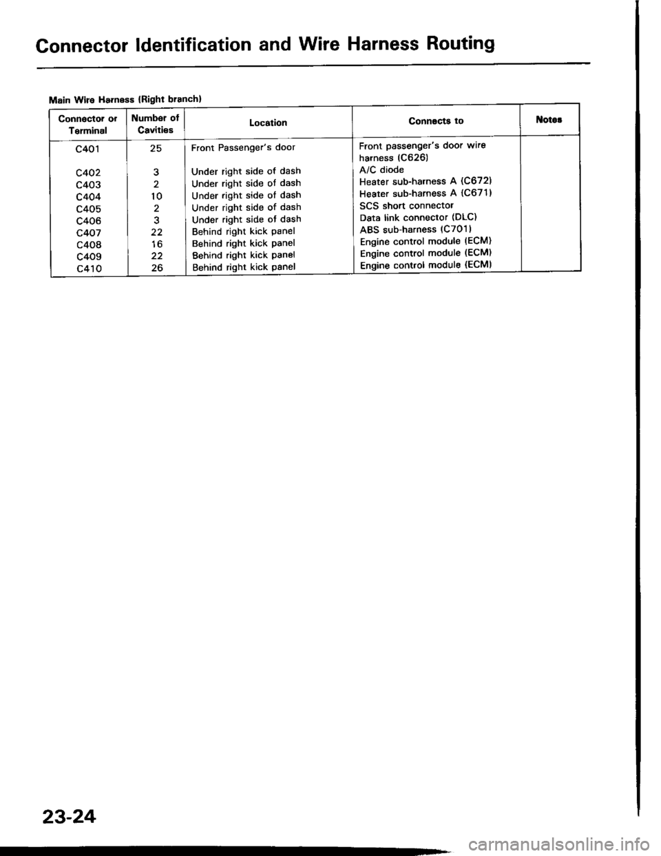
Connector ldentification and Wire Harness Routing
Main Wire Ha.ness {Right branch}
Connactor or
Terminal
Numbsr of
Caviti€sLocationConnscts tottlotor
c401
c402
c403
c404
c405
c406
c407
c408
c409
c410
,E
10
2
22
lo
22
26
Front Passenger's door
Under right side of dash
Under right side ot dash
Under right side of dash
Under right side of dash
Under right side ot dash
Behind right kick panel
Behind right kick panel
Behind right kick panel
Behind right kick panel
Front passenger's door wire
harness (C626)
A/C diode
Heater sub-harness A (C672)
Heater sub-harness A {C671}
SCS short connectol
Data link connector (DLC)
ABS sub-harness (C7011
Engine control module (ECM)
Engine control module (ECM)
Engine control module (ECMI
23-24
Page 1134 of 1413
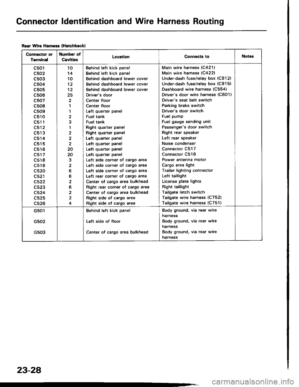
Connector ldentification and Wire Harness Routing
Roar wiro Harn$s (Hatchbsckl
Connector or
Torminal
Numbor of
CavitiosLocationConnecta tollotos
c501
c502
c503
c504
c505
c506
c507
c508
c509
LStt
c51 1
c512
c513
c514
c515
c516
c517
c5r 8
c519
c520
c521
c522
c523
c524
c525
c526
10'14
10
12
25
2
1
1
2
I
2
20
20
2
6
b
2
2
2
4
Behind left kick panel
Behind left kick panel
Behind dashboard lower cover
Behind dashboard lower cover
Behind dashboard lower cover
Driver's door
Center tloor
Center lloor
Left qusrter panel
Fuel tank
Fuel tsnk
Right quarter panel
Right quarter panel
Left quarter panel
Left quarter panel
Left quarter panel
Left quarter panel
Left side corner of cargo area
L€ft side corner of cargo area
Left side corner of cargo area
Left rear corner of cargo area
Center ot cargo area bulkhead
Right rear cornor oJ cargo area
Center of cargo area bulkhsad
Right side of cargo area
Right side of cargo area
Main wire harness (C4211
Main wire harness (C422)
Under-dash fuse/relay box (C912)
Under-dash fuse/relay box (C91 5)
Dashboard wire harness (C554)
Driver's door wire harness {C6011
Driver's seat belt switch
Palking brake switch
Driver's door switch
Fuel pump
Fuel gauge sending unit
Passenger's door switch
Right rear speaket
Left rear speaker
Noise condenser
Connector C517
Connector C516
Power antenna motor
Cargo area light
Traile. lighting connector
LeJt taillight
License plate lights
Right taillight
Tailgate latch switch
Tailgate wire harness (C752)
Tailgate wire harness (C751)
G501
G502
G503
Behind left kick psnel
Left side of Jloor
Center ot cargo area bulkhead
Body ground, via rear wire
harness
Body ground, via rear wire
harness
Body ground, via rear wire
harness
23-28