Page 1332 of 1413
Power Windows
Master Switch Input Test (Sedan)
NOTE; The control unit is built into the Dower window
maste. switch, and onlv controls driver's door window
ooerations.
1. Remove the driver's door panel and disconnect the
16-P and 1-P connectors from the master switch.
2. Inspect the connector and socket terminals to be
sure they are all making good contact.
a lf the terminals are bent, loose or co.roded, reDair
them as necessary. and techeck the system.a It the terminals look OK, make the following in-
put tests at the connecto..- It a test indicates a problem, tind and correct
the cause, then recheck the system.- lf allthe input tests prove OK, the power win-
dow master switch must be faulty; replace it.
23-226
BEDI'EL I GRN
8LU/YEL I YEL/BLK
View from wire side
View lrom wire side
Page 1336 of 1413

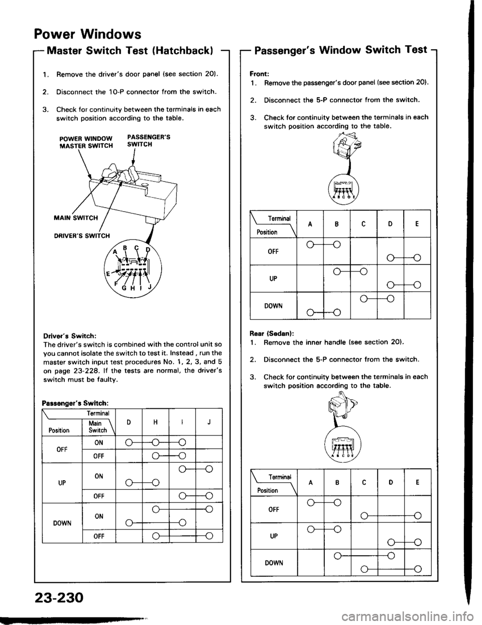
1.Remove the drivef's door panel (see section 201.
Oisconnect the 1O-P connector from the switch.
Check tor continuity between the terminals in each
switch position according to the table.
pOWERWTNDOW PASSENGEB'S
MASTER SWTTCH SWITCH
Drive.'s Switch:
The driver's switch is combined with the control unit so
you cannot isolate the switch to test it. Instead , run the
master switch input test procedures No. 1, 2, 3, and 5
on page 23-228, lf the tests are normal, the d.ivet's
switch must be faultv.
i1\i
\4r-I^l,r
)rvti\
.Fi'ilj
Passengsl'r Switch:
Te.minsl
DHJI Msin \Position I Switch \
OFFONo-(J--o
OFFo--o
UPONo---o
o--
OFFo--o
DOWNONo-
o--o
--o
OFFo--o
Power Windows
Master Switch Test (HatchbacklPassenger's Window Switch Test
23-230
Front:
1 . Remove the passenger's door panel {see section 20).
2. Disconnect the 5-P connector from the switch.
3. Check for continuity between the terminals in each
switch position sccording to the table.
Rear (Sedanl:
1. Remove the inn€r handle (see section 2O)'
2, Disconnect the 5-P connector from the switch.
3. Check for continuity between the terminals in each
switch position according to the table.
Torminal
il;_\
ARD
OFFo-
--o
UPo---o
G_--o
DOWr.lo---o
Terminal
;;__\ID
OFFG_--o
o---o
UPG_--o
o---o
DOWNo---o
o-
Page 1337 of 1413
Master Switch ReplacementPassenger's Window Switch
Hatchback:
1. Remove the driver's door panel (see section 20).
2. Disconnect the 1O-P connector lrom the switch,
3, Remove the three mounting screws and the switch.
Sedan:
1. Remove the driver's door panel (see section 2O).
2. Disconnect the 1 6-P and 1-P connectors from the
switch.
3. Remove the two mounting screws and the switch.
POWER MIRRORswtTcH
scREws
Replacement
Flont:
1 . Remove the passenger's door panel (see section 201.
2. Disconnect the 5-P connector from the switch.
3. Remove the two mounting screws and the switch.
Roar (S6danl:
1. Remove the inner handle (see section 20).
2. Disconnect the 5-P connector from the switch.
3. Remove the two mounting screws and the switch.
w|I{Dow.swtTcH
swtTcl{
INNER HANDLE
23-231
Page 1338 of 1413

Power Windows
Driver's Window MotorTest
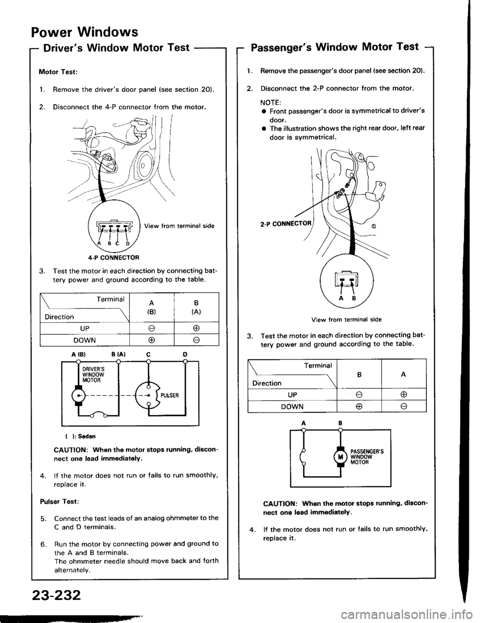
1. Remove the
2. Disconnect
Motor Test:
View from lerminal side
4.P CONNECTOR
3. Test the motor in each direction by connecting bat-
tery power and ground according to the table.
{ }: Sodan
CAUTION: When the motor stops running. discon-
nect one lead immediately.
4. lf the motor does not run or tails to run smoothly,
replace it.
Pulser Test:
5. Connect the test leads of an analog ohmmeter to the
C and D terminals.
6- Run the motor by connecting power and ground to
theAandBterminals,
The ohmmeter needle should move back and torth
alternately.
driver's door panel (see section 20).
the 4-P connector trom the motor.
. ,-,.f,/l l/
NZJI I
..Q]qql ,fiftl I
$e /tE \
Terminal
Direction(B)B
{A}
UP@
DOWNO
Passenger's Window Motor Test
l.
2.
Remove the passenger's door panel (see section 20).
Disconnect the 2-P connector from the motor.
NOTE:
a Front passenger's door is symmetricalto driver's
ooor.
a The illustration shows the right rear doot, left rear
door is svmmetrical.
2.P CONNECTOR
View from terminal side
3. Test the motor in each direction by connecting bat-
tery power and ground according to the table.
CAUTION: When the motor stops tunning. discon-
nect on€ lead imm€diately.
lf the motor does not run or Jails to run smoothly,
reDlace it.
Terminal
O*** \
BA
UPoo
DOWN@
23-232
-'
Page 1342 of 1413
Power Door Locks
Control Unit Input Test
Remove the driver's door panel {see section 2O).
Disconnect the 1+P connector Jrom the control unit.
Inspect the connector and socket terminals to be
sure they are all making good contact.
a It the terminals are bent. loose or corroded, repair
them as necessary. and recheck the system.
a lf the terminals look OK. make the following in-
put tests at the connector.- lf any test indicates a problem, find and cor-
rect the cause, then recheck the syslem.
lf all the input tests prove OK, the control unit
must be faultv; replace it.
POWER DOOR LOCK
CONTROL UNIT
t4-P COI{NECTOR
View from wiro side
23-236
Page 1344 of 1413
1.
Power Door Locks
Driver's Door Lock Actuator Test
Remove the door panel (see section 20).
Disconnect the 6-P connector from the actuator.
Check actuator operation by connecting power and
ground according to lhe table.
CAUTION: To prevont damago lo tho actualol, ap-
ply battery voltage only momentarily.
lf the actualor fails to work properly, replace it.
Terminal
;;"
---\D
LOCK@o
UNLOCKlJ@
23-238
Terminal
il;----tI
LOCKoo
UNLOCKo--o
5. Check fo. continuity between the terminals in each
switch position according to the table.
DOOR LOCK KI{OB
Page 1345 of 1413
Passenger's Door Lock Actuator Test
1. Remove the door panel (see s
2. Disconnect the 2-P connector
Front Passonger's Door:
terminal side
2-PCONNECTOR
section 20).
r from the actuator.
Rear Passenger's Dool:
NOTE: Left rear actuato, is shown, right rear actuator
is similar.
View from terminal side
Check actuator operation by connecting power andground according to the table.
CAUTION: To prevent damage to the actuator, ap-ply battery voltage only momentarily.
4. It the actuator fails to work properly, replace it.
ACTUATOR
Terminal
Position \
B
LOCK@
UNLOCK@,-,
23-239
Page 1346 of 1413
Power
Driver'
Door
s Dool
Locks
Key CylinderFront Passenger's Door Key Gylindet
Switch Test
1. Remove the door Danel {see section 2O).
2. Disconnect the 3-P connector trom the switch.
FRONTPASSENGER'SDOOB KEYCYLINDERswtTcH
coN ECIOR
3. Check tor continuitv between the terminals in each
switch position according to the table.
tfil*rr
Terminal
P""ft;---lABc
LOCKo----o
OFF
UNLOCKo----o
UNLOCK
-r--O
I LOCK
Switch Test
1. Remove the door panel (see section 20).
2. Disconnect the 2-P connector from the switch.
terminal side
3. Check for continuity between the terminals in each
switch position according to the table.
Position
TerminalB
UNLOCKGo
OFF
UNLOCK<
I
23-240