Page 1198 of 1413
lgnition System
Distributor Installation
Coat a new O-ring with engine oil, then install it.
Slip the distributor into position.
NOTE: The lugs on the end of the distributor and
its mating grooves in the camshaft end are both off-
set to eliminate the possibility ot installing the dis-
tributor 18Oo out of time.
DISTRIBUTOR END CAMSHAFT END
Install the mounting bolts and tighten them tem-
porarily.
Connect the 2-P and 8-P connectors to the dis-
tributor.
24 N.m (2.4 kgf'm' 17 lbt'ft|
23-92
5. Connect the ignition wires as shown.
Set the timing with a timing light (se€ page 23-89).
After setting the timing, tighten the mounting bolts.
Page 1201 of 1413
lgnition Coil Test
With the ignition switch OFF, remove the distribu-
lor cap.
Remove the two screws to disconnect the BLK^/EL
and WHT/BLU wires from terminals A (+ ) and B ( - )respectively.
3. Using an ohmmetet, measur€ tesistance betwe€nthe terminals, Replace the coil if the resistance is notwithin specifications.
NOTE: Resistance will vary with th€ coil t€m9er-ature; sp€cifications are at 68oF l20oC)
Prlmary Winding Rosistanco(8otwo6n tho A and B torminalsl: 0.6-0.g ohmsSecondary Winding Rssistanc6(Botwoon the A and socondary winding tomlnalsl:12.8 - 19.2 kO
lgnition Coil Replacement
1 . With the ignition switch OFF, remove the disrribu-
tor cap, rotor, and cap seal, then remove the leak
cover.
Remove the two screws to disconnect the BLK/YEL
and WHT/BLU wires from the coil.
Remove the two screws and slide the ignition coil
out of the distributor housing,
CAP SEAL
3.
A l+)
I
t
l
11
L
WHT/BLU WIRE
B {-}
23-95
Page 1202 of 1413

lgnition
lgnition
System
Control Module (lCMl Input Test
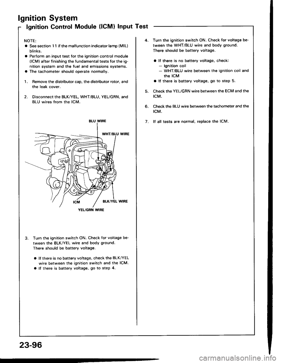
NOTE:
a See section I 1 if the malfunction indicator lamD (MlL)
blinks.
a Pertorm an input test for the ignition control module
(lCM) after finishing the fundamental tests for the ig-
nition system and the fuel and emissions systems.
a The tachometer should operate normally.
1. Remove the distributor cap, the distributor rotor, and
the leak cover.
2. Disconnect the BLK/YEL, WHT/BLU, YEL/GRN, and
BLU wires from the lCM.
3. Turn the ignition switch ON. Check for voltage be-
tween the BLK/YEL wire and body ground.
There should be battery voltage.
a lf there is no battery voltage, check the BLK^/EL
wire between the ignition switch and the lCM.
a lf there is battery voltage, go to step 4.
YEL/GRN wlRE
4.Turn the ignition switch ON. Check for voltage be-
tween the WHT/BLU wire and body ground.
There should be battery voltage.
a lf there is no battery voltage, check:- lgnition coil- WHT/BLU wire between the ignition coil and
the ICM
a lf there is battery voltage. go to step 5.
Check the YEL/GRN wire between the ECM and the
tcM.
Check the BLU wi.e between the tachometer and the
rcM.
It all tests are normal, replace the lCM.
6.
7.
23-96
Page 1203 of 1413

Spark Plug Inspection
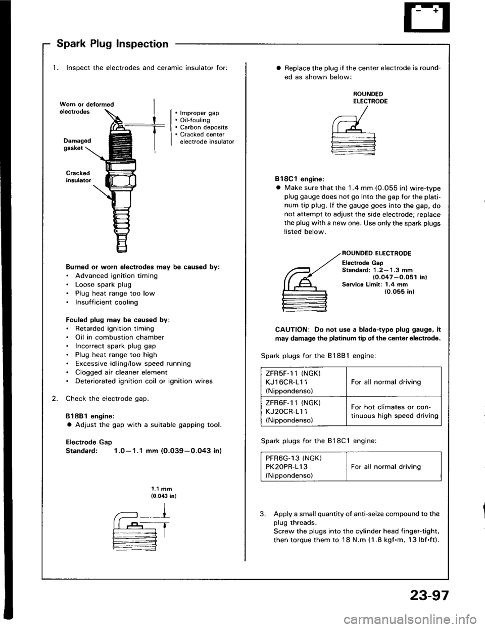
1. Inspect the electrodes and ceramic insulator for:
. rmproper gap. Oil-touling. Carbon deposits. Cracked centerelectrode insulatorDamagedgask6t
Burned or worn electlodes may be caused by:. Advanced ignition timing. Loose spark plug. Plug heat range too low. Insufficient cooling
Fouled plug may be caused by:. Retarded ignition timing. Oil in combustion chamber. lncorrect spark plug gap. Plug heat range too high. txcessive idling/low speed running. Clogged air cleaner element. Deteriorated ignition coil or ignition wires
Check the electrode gap.
Bl88l engine:
a Adjust the gap with a suitable gapping tool.
Electrode Gap
Standard: 1.0-1.1 mm (O.O39-0.O43 in)
1.1 mm{0.0,$ in)
Replace the plug if the center electrode is round-
ed as shown below:
ROUNDEDELECTROOE
Bl8Cl engine:
a Make sure that the '1.4 mm (0.055 in) wire-typeplug gauge does not go into the gap for the plati-
num tip plug. lf the gauge goes into the gap, do
not attempt to adjust the side electrode; replace
the plug with a new one. Use only the spark plugs
listed below.
ROUNDEO ELECTRODE
Electrode GapStandard: 1 .2-'l .3 mm{0.047 -O.051 in)Service Limit: 1.4 mm{0.055 in)
CAUTION: Do not use a blade-type plug gaugs, it
may damage the platinum tip of the center olectrodo.
Spark plugs for the 81881 engine:
Spark plugs for the B'l8Cl engine:
PFR6G_13 (NGK) IPK2OPR-113 I For all normal driving
{Nippondenso)
3. Apply a small quantity ol anti-seize compound to the
plug threads.
Screw the plugs into the cylinder head iingef-tight,
then torque them to 18 N.m (1.8 kgf.m, 13lbf.ft).
ZFRsF-1 1 (NGK)
KJl6CR-11 1
(Nippondenso)
For all normal driving
ZFR6F-1 1 (NGK)
KJ2OCR-11 1(Nippondenso)
For hot climates or con-
tinuous high speed driving
23-97
Page 1205 of 1413
Circuit Diagram
UI,IDER - HOOD FUS€/REI.AY 8OX
*1 :USA+2 llo.24 ll SAl: 81881 .mintlo.24 {2041: 818C | .niin6
. NTEGRATEDCOMTNOL UMT. aBs coilTRor- uNn
VI
I
ECM
V
I
I
UNDER_OASHFUSE/REIAY 8OX
oiotG401
No.4t 11004) /a ilo.39l50Al
Fr€|'l) wNort'lc
AI.TERNATOR
23-99
Page 1211 of 1413
Alternator Overhaul
CAUTION: Do not r€move th€ pulley unl€Es the t.ontbearing needs r6placsm6nt.
To loosen the pulley locknut, use 10 mm and 22 mmwrenches. It necessary, use an impact wrench.
Test, page 23-107SPAC
REAR BEARING
ER RING
rl
@n
CAUTION: Do not get grease
or oil on the slip rings.
HOLDERTOR
ARUSH HOLOER
FRONT BEARING
PULLEY LOCKI{UT1'll N.m 111.3 kgt.m,82 tbf.trl
STATOR/DRIVE ENDHOUStt{G
BBUSHINSULA
)
(@P "
STATOR THROUGHBOLT
VOLTAGE REGULATOR
DIODE IRECTIFIER) ASSEMBLYTest, page 23-106
6
q
%A
re
TERMINAL INSULATORqt
PULLEY LOCKNUT111 N.m (1 1.3 kgt.m, 82 lbf.ft)
PULLEY
10 mm BOX WRENCH
REAR HOUSING
Inspection, page 23-
fu"- "o*n.r" ".,"- BRACKET
23-105
Page 1213 of 1413
Rotor Slip Ring Test
1 . Check thst there is continuity between thg slip rings.
ROTOR SHAFT
Check th8t there is no continuity betw€en the slip
rings and the rotor or rotor shaft.
lf the rotor fails either continuity check, rsplace th€
alternator.
2
3
Stator Test
1. Chock that there is continuity between each pair ofl6ads.
Ch6ck that there is no continuity between each lead
and the coil core.
lf th€ coil fsils either continuity check. replace the
alt6rnator.
cotl coRE
23-107
Page 1219 of 1413
Gauge Assembly
Component Location Index
CAUTION:
a All SRS electrical wiring harnosses are cov€rod withyellow insulation.
a Bofore disconnecting any prn ot th€ SRS wire har-ness, connect tho short connector(sl.a R€place th6 entirs affGcted SRS halne$ assembly ifit has an open circuit o? damaged wiring.
SRS MAIN HARNESS{Cov.r6d with yollow inrularionl
GAUGE ASSEMBLYGauge Location Index, page 23-114Indicator Location Index, page 23-1 14Terminal Location Index, page 23-114Bulb Location. page 23-'l 15Disassembly. page 23-1 19Removal, page 23-118
FUEL GAUGE SENDING UNtTTest, page 23'124Repfacemenr, page 23-124
VEHICLE SPEEO SENSOB IVSS}Test, page 23-120fnput Test. page 23-120Repfacement, page 23-122
PARKITTG BRAKE SWITCHTest, page 23-127
BRAKE FLUID LEVEL SWITCHTesr, page 23-127
EI{GINE OIL PBESSURE SWITCHTest, page 23-122
ENGINE COOLANT TEMPERATURE IECTI GAUGESENOING UNITTest, page 23-126
(C61'ios tho SBS indicator signal)
23-113