Page 960 of 1413
Interior Trim
Replacement
a W€al gloves to remove and installth€ trim and panols.a When prying with a flat tip screwd.ivor. wrap it withprotective tap€ to prevent damaga.
NOTE: Take care not to bend or scratch the trim andDanels.
Kick panel/Front pillar trim removal:
l. Remove the kick Danel.
< : Clip locations
A< | Cllp, 1 B< : Ctip, 1 CV : C[p, 1
Jtl,Ml*
U ry-ry
NOTE: Remove the driver's kick panel while pullingthe hood release handle.
KICK PANEL
Pull the door trim back, then remove the front oillarrflm.
< : Clip locations, 4
lnstallation is the reverse of the removal procedure.
NOTE: lf necessary, .eplace any damaged clips.
FRONT PILLAR
20-91
Hatchback
Rear trim panet/Side trim panel/Ouarter pillar trim p-l16moval:
1. Open the hatch.
2. Remove the .ear shelt.
Remove the rear seat (see page 20-'l08).
Remove the trunk mat and spare tire lid.4.
ao..t dr
REAR SHELF
REAR SHELF
TRUNK MAT
SPARE TIRE LID
Page 1015 of 1413

Hatch
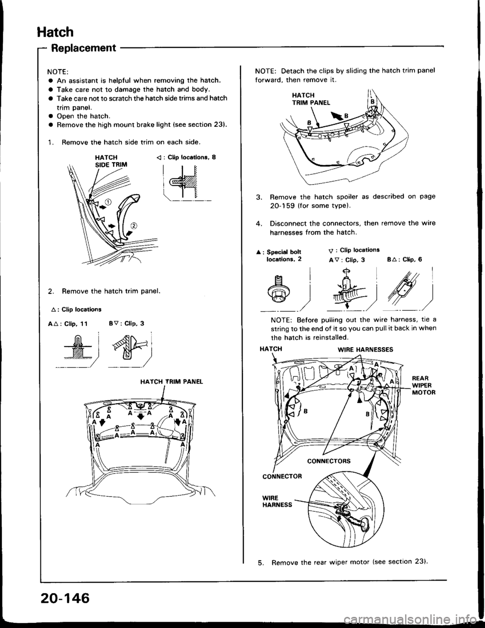
Replacement
NOTE:
a An assistant is helpful when removing the hatch.
a Take care not to damage the hatch and body.
a Take care not to scratch the hatch side trims and hatch
tnm paner.
a Open the hatch.
a Remove the high mount brake light {see section 23).
1. Remove the hatch side trim on each side.
HATCH< : Clip locations, 8
2. Remove the hatch trim panel.
A : Clip localions
AA : Clip, 11 BV : Clip, 3
W', dtri
::::/ _:_/
HATCH TRIM PANEL
NOTE: Detach the clips by sliding the hatch trim panel
forward, then remove it.
3. Remove the hatch spoiler as described on page
20-159 (for some type).
4. Disconnect the connectors, then remove the wire
harnesses from the hatch.
: Speclal boltlocetlons,2
V : Clip locations
Av : Clip, 3 BA: CliP, 6
4
t+Ltfrl
l'R@t
,/ L,/
A
@
l
)
NOTE: Before pulling out the wire harness, tre a
strinq to the end of it so you can pull it back in when
the hatch is reinstalled.
HATCI{WIRE I{ARNESSES
CONNECTORS
CONNECTOR
WIREHARNESS
20-146
5. Remove the rear wiper motor (see section 23).
Page 1018 of 1413

20 mm (O.79 inl
SUPPORT STRUT
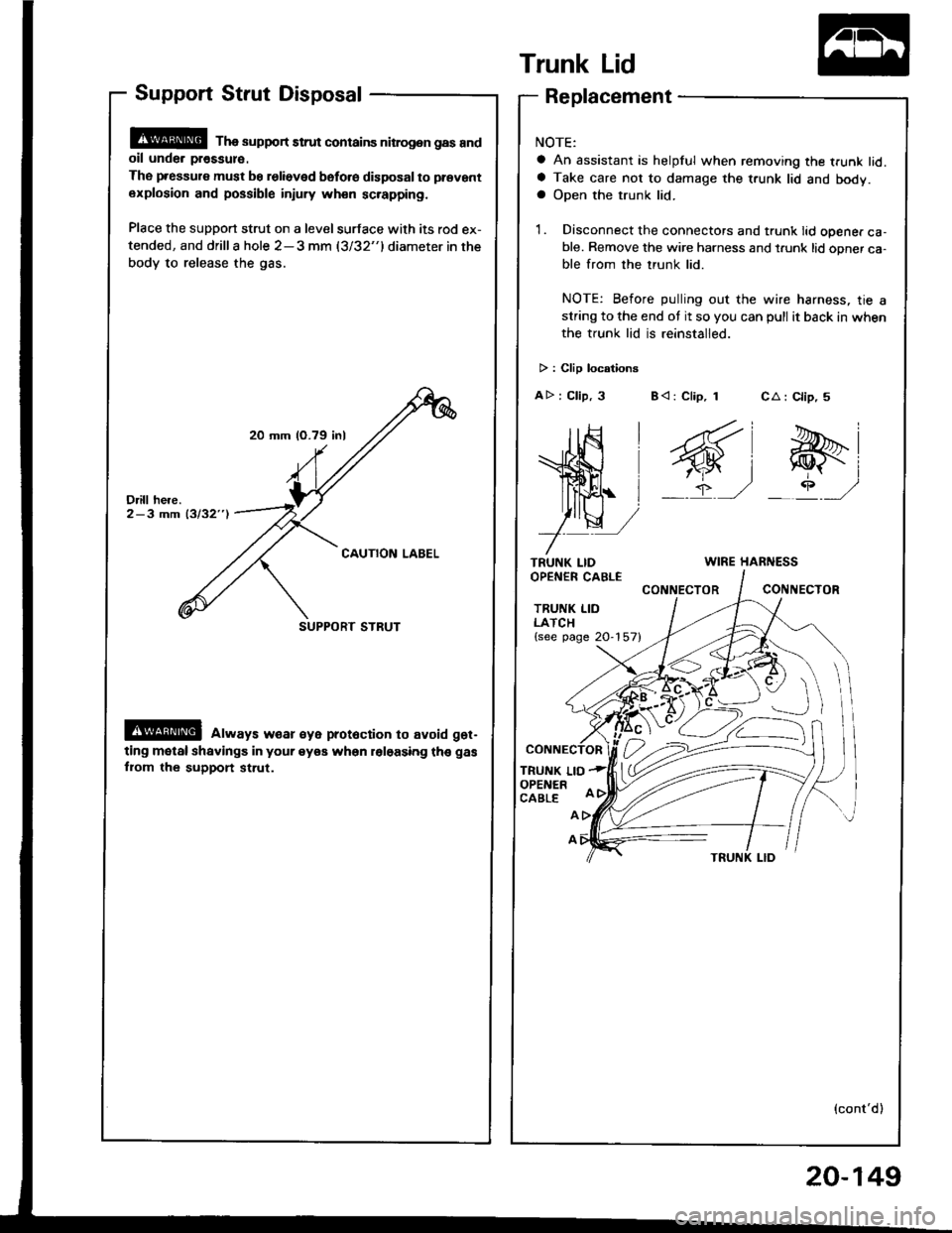
Support Strut Disposal
@ Tha support strut contains nitrog.n gas andoil unde. pr€ssul€.
The pressure must be relieved bsfo.e disposal to prevant
explosion and possible injury wh€n sc.apping.
Place the support strut on a level surface with its rod ex-
tended, and drilla hole 2-3 mm (3/32"1diameter in the
body to release the gas.
@ always w€ar €ye prot6ction to avoid get-
ting motal shavings in your eyea when roloasing th€ gas
fiom the support st.ut.
Trunk Lid
TRUNK LIDOPEN€R CABLE
TRUNK LIDLATCH{see page 20-157}
TRUNK LIOOPENERCABLE
CA : Clip, 5
e-i
_rP ,/
Replacement
NOTE:
a An assistant is helpful when removing the trunk lid.a Take care not to damage the t.unk lid and body.a Open the trunk lid.
1. Disconnect the connectors and trunk lid opener ca-ble. Remove the wire harness and t.unk lid opner ca-ble from the trunk lid.
NOTE: Before pulling out the wire harness, tie astring to the end ot it so you can pull it back in when
the trunk lid is reinstalled.
> : Clip locationg
AD : Clip, 3 B< : Clip, 1
WIRE HARNESS
CONNECTORCONIIECTOR
A
A
(cont'd)
20-149
Page 1027 of 1413
Retainers and WeatherstriP
Replacement
CAUTION: Wear gloves to lemov€ and install tho i€tain€rs'
NOTE: Take care not to bend the retarners.
< : Screw localions, 19 < : Clip locations, I
| .€\
!:
l{SHOP TOWELq
CENTER PILLARMOLDING
Boot side section:
I
RETAINER
lnstallation is the reverse of the removal procedure.
NOTE:
a Check the weatherstrip lor damage or deterioration, and replace if necessary'
a After installing the weatherstrip, check for water leaks'
a lf necessary, adjust the position of the door glass (see page 20-40)
a It necessarv, replace any damaged clips.
Center oillar section:
FRONT CENTER PILLAR
CENTER PILI-ARMOLDING
NOTE: The numbers atter the part names
show the quantities ot the parts used
!9
RETAINER
WEATHERSTRIP
REAR CLIP
RETAINER
WEATHERSTRIP
20-158
Page 1028 of 1413
Hatch Spoiler
Replacement
a Take care not to scratch the hatch.a Open the hatch.
1. Remove the hatch side trim and hatch trim panel (seepage 2O-146).
2. Remove the nuts and disconnect the connector.
: Nut locations, 4
6 x 1.0 mm
Ch 9.8 N.m(J (1.0 ksl m, I__. 7,4b1!t ,/coI{t{EcroR
Remove the hatch spoiler by turning the clip nut onthe left side counterclockwise.
HATCH SPOILER
3. Installation is the reverse of the removal procedure.
Fender Well Trim and
Wheelhouse Protector
Replacement
a Take care not to bend the tender well trim.a Before installing the lender well trim, clean the bodvbonding surface with a sponge dampened in alcohol.a After cleaning, keep oil, g.ease or wafer lrom getlingon the surface.
> i Scr€w locations.
I
ADHESIVEFENDER WELLTRIM
20-159
Page 1031 of 1413

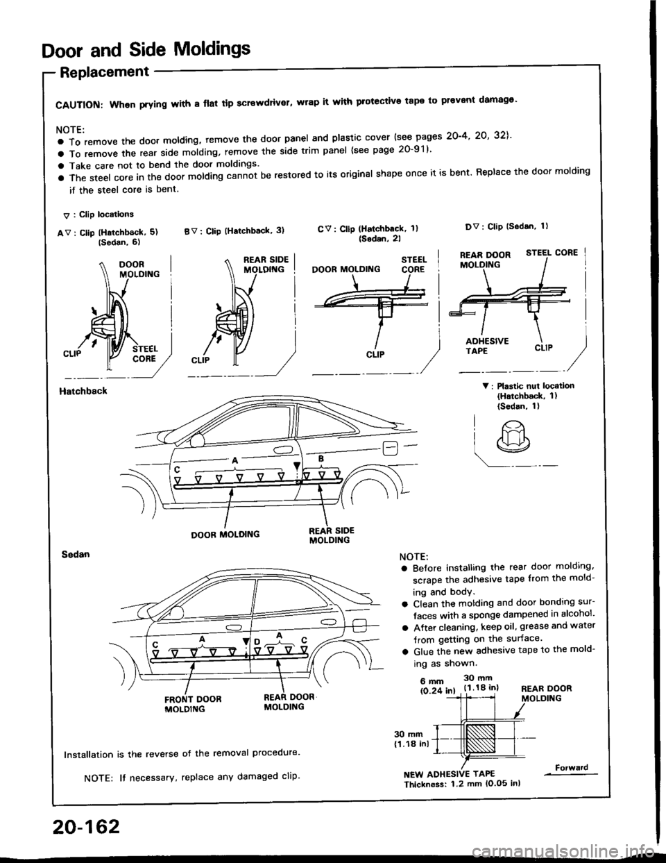
Door and Side Moldings
Replacement
CAUTION: When prying with 8 flal tip screwdriver, wrap it with protective tape to pr€vont damag€'
NOTE:
a To remove the doot moldlng, temove the door panel and plastic cover {see pages 2O-4' 2O' 32],'
a To remove the rear side molding, remove the side trim panel (see page 20-91)
a Take care not to bend the door moldings.
a The steel core in the door molding cann-ot be restored to its original shape once it is bent. Replace the door molding
if the steel core is bent.
V : Clip locations
av : cllp (Hatchb6ck, 5) BV: clip (Hatchback' 3)
V: Plastic nui locatlon(Hatchback, 1)(Sedan, 1)
CV: Cllp (Halchback, 1l{Sodan,2l
Dv: Clip lsodan, 1)
Hatchbsck
20-162
30 mm(1.18 inl
lnstallation is the reverse
NOTE: It necessary,
oJ the removal Procedure.
replace any damaged cliP.NEW ADHESIVE TAPE
Thicknoss: 1.2 mm lo.o5 inl
Forward
STEEL
CLIP
O'
lr>
r9
NOTE:
a BeJore instatling the rear door molding,
scrape the adhesive tape from the mold-
ing and body.
a Clean the motding and door bonding sur-
Jaces with a sponge dampened in alcohol'
a Atter cleaning, keep oil, grease and water
Jrom getting on the surface.
a Glue the new adhesive tape to the mold-
ing as shown.
6mm 30mm
ls 2f 61 . t.l.18 inlREAR DOORMOLDING
Page 1033 of 1413
Rear Emblems
lnstallation
Align the applicalion tape with the rear turn signal light and the gap between the taillight and body, as shown, then press
the emblem into place. Remove the applicataon tape'
NOTE:
a Before applying, clean the body surlace with a sponge dampened in alcohol'
a After cleaning, keep oil, grease and water from getting on the surface'
a When applying, make sure there are no wrinkles in the emblem'
Attachment Point:
REAR TURNSIGNAL LIGHTHatchback
REAR TURNSIGNAL LIGHT
20-164
!---_-----------,-i-J
TAILLIGHT
Page 1074 of 1413

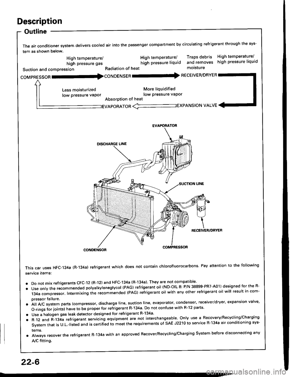
Description
Outline
The air conditioner system delivers cooled air into the passenger compartment by circulating refrigerant through the sys-
tem as shown below.
CONDENSOR
This car uses HFC-134a {R-134a) refrigerant which does not contain chlorofluorocarbons Pay attention to the following
service items:
. Do not mix refrigerants CFC-I2 (R-l21 and HFC-134a (R-134a) They are not compatible'
. Use onty the recommended potyatkytenegtycol {PAG) refrigerant oil (ND-OIL 8: P/N 38899-PR7-A01) designed for the R-
134a compressor. Intermixing the recommended (PAG) refrigerant oil with any other refrigerant oil will result in com-
pressor tailure.
.A||lvcsystemparts(compressor.dischargeIine,suotionIine,evaporator,condenser.receiver/dryer,expansionva|ve.
o-ringsforioints}havetobeproperforre'rigerantR-l34a.DonotconfusewithR.l2parts.
. Use a halogen gas leak detector designed for refrigerant R-134a'
. R-.12 and C-l34a refrigerant servicing equipment are not interchangeable. Only use a Recovery/Recyclins/Charging
System that is U.L.-listed and is certifLd to meet the requirements of sAE J2210 to service R-134a air conditioning sys-
rems.
. Always recover the refrigerant R-134a with an approved Recover/Recycling/Charging System before disconnecting any
A,/C fitting.
coMpRESsoR -coNDENSER - RECEIVER/DRYER
High temperature/
high pressure gas
Suction and comPression
Less moisturized
low pressure vaPor
High temperature/ Traps debris High temperature/
hilh pressure liquid and removes high pressure liquid
Radiation of heat molsture
More liquidified
low Pressure vaPor
Absorption of heat
EVAPORATOR <-'----------.- EXPANSION VALVE
EVAFORATOR
22-6