Page 1151 of 1413
BEAR WII{DOWDEFOGGERGROUND IVIBE
HATCHWIRE
SPOILER SUB.HAFIIESS
c763
'r]fi
23-45
Page 1182 of 1413

Starting System
Startel Test
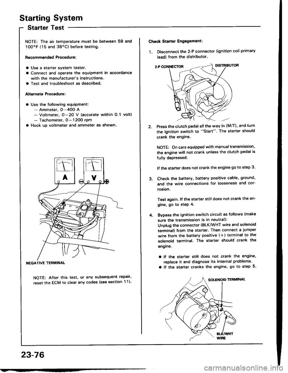
NOTE: The air temDerature must be between 59 8nd
10OoF (15 and 38oC) before testing.
Recommendsd Procodure:
a Use a staner svstem tester.
a Connect and operate the equipment in accordance
with the manutacturer's instructions.
a Test and troubleshoot as described.
Altohato Procedure:
a Use the following equipment:- Ammeter. 0-4OO A- Voltmeter, O- 20 V {accurate within 0.1 volt)
- Tachometer, O- 120O rpm
a Hook up voltmeter and ammeter as shown'
NEGATIVE TERMINAL
NOTE: After this test, or any subsequent repair,
reset the ECM to clear any codes (see section 1 1)
23-76
2.
Chock Stan€r Engag6ment:
1. Disconnect the 2-P connector (ignition coil primary
lead) from the distributor.
Press the clutch pedal allthe way in (M/T), and turn
the ignition switch to "Start". The starter should
crank the engine.
NOTE: On cars equipped with manual transmission,
the engine will not crank unless the clutch pedal is
fully depressed.
lf the staner does not crank the engine go to step 3.
Check the baftery, battery positive cable, ground,
and the wire connections for looseness and cor-
rosion,
Test again. lf the starter still does not crank the en-
gine, go to step 4.
Bvpass the ignition switch citcuit as follows {make
sure the transmission is in neutral):
Unplug the connector (BLK/WHT wire and solenoid
terminsl) trom the starter. Then connect a jumper
wire from the battery positive ( + ) terminal to the
solenoid terminal. The starter should crank the
engrne.
a lf the starter still does not crank the engine,
replace it and diagnose its internal problems.
a lf the starter cranks the engine, go to step 5.
J.
4.
Page 1184 of 1413
Starting System
Clutch Interlock Switch Test
1 . Remove the dashboard lower cover and knee bolster
(see page 23-70), then disconnect the 2-P connec-
tor from the switch.
2. Check tor continuity between the terminals accord-
ing to the table.
lf necessary. replace the switch or adjust the switch
oosition (see section 12).
Starter Solenoid Test
1. Check for continuitv between the tetminals accotd-
ing to the table.
HOLD - |l{ COIL
23-78
Tsrminal
CoilMDHousing
HOLD- INo----c
PULL- INo----.oClutch Pedal
T€rminalAB
RELEASED
PUSHEDoo
Pt LL- tt{ coll
Page 1188 of 1413
Starting System
Armature Inspection and Test
1 . Inspect the armature for wear or damage due to con-
tact with the field coil magnets.
Inspect tor damage
A dirtv or burnt commutator surface may be l€sul-
faced with emery cloth or a lathe within the follow-
ing specilications.
Commutator Diamet€r
Stsndald (N6w): 29.9-3O.O mm (1.17-1.18Inl
Selvico Limit: 29 mm (1.14 lnl
VERNIEB CALIPER
23-82
3.
4.
Commutrtor Runout
Standard (Naw): 0-O.O2 mm (0-O.OO08 inl
Sowico Limit: 0.O5 mm (O.O02 inl
lf the commutator runout and diamete. are within
limits, check the commutator tor damage or for car-
bon dust or brass chips between the segments.
lf the surf6c6 is dirty, recondition it with # 50O or
# 600 sandpsper.
COMMUTATOR
Page 1189 of 1413
Check for mica depth. It necessary, undercut micawith a hacksaw blade to achieve proper depth.
ITOT GOOO
MICA DEPTH
Commutator Mica D6pth
Stsndard {Nsw):0.5-0.8 mm (O.O2-0.03 in}Sslvice Limit: 0.2 mm (O.OO8 inl
Check tor continuity between the segments of thecommutator. lf an open circuit exists between anvsegments, replace the armatute.
M
ARMATURE TESTER
ARMATUFE
Place the armatute on an armature tester. Hold ahacksaw blade on the armature core,
HACKSAW BLADE
It the blade is attracted to the core or vibrstes whilethe core is turned, the armature is shorted. Reolacethe armature.
Check with an ohmmeter that no continuity existsbetween the commutator and armatute coilcore. andbetween the commutator and armature shaft. lf con_tinuity exists, replace the armature
COMMUTATOR
8.
SHAFT
23-83
Page 1192 of 1413

Starting System
Performance Test
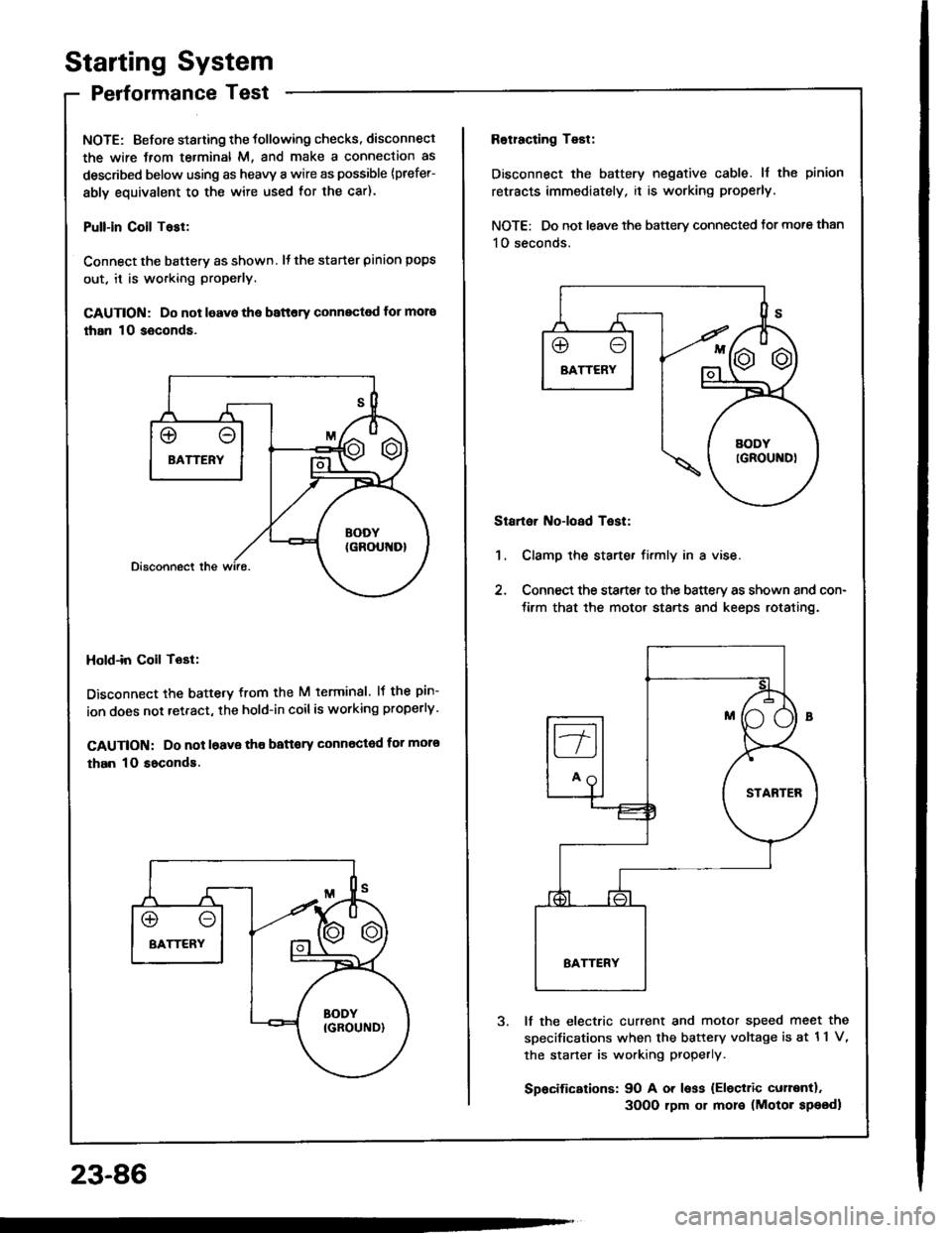
NOTE: Before staning the tollowing checks. disconnect
the wire Jrom te.minal M, and make a connection as
described below using as heavy a wire as possible {prefer-
ably equivalent to the wire used for the car).
Pull-in Coil Tasl:
Connect the batterv as shown. It the starter pinion pops
out, it is working properly.
GAUTION: Do not leavo the battery connectod for mora
than 10 seconds.
Hold-in Coil Tost:
Disconnect the battetv from the M terminal. lf the pin-
ion does not retract, the hold-in coilis working properly.
CAUTION: Do not l6ave tho battory Gonnected for moro
than 10 soconds.
23-86
Rotracting Test:
Disconnect the battery negative cable. ll the pinion
retracts immediately, it is working properly.
NOTE: Do not leave the battery connected tor more than
1O seconds.
Startoi Noioad Test:
1, Clamp the starte. firmly in a vise.
2, Connect the starter to the battery as shown and con-
tirm that the motor starts 8nd keeps rotating.
It the electric current and motor speed meet the
sDecifications when the battery voltage is at 11 V,
the staner is working properly.
Spacifications: 90 A or less {Eleciric curentl.
3OO0 rpm or more (Motor speodl
Page 1193 of 1413
lgnition System
Gomponent Location Index
IGNITION TIMING CONTROL SYSTEMa Troubleshooting, section I1a Inspection and setting, page 23-89
DISTRIBUTORTop End Inspection, page 23-91Removal/lnstallation, pages 23-91, 92Overhaul, page 23-93Reassemblv, page 23,94lgnition Coil Test/Replacement, page 23-95lgnition Control Module {lCM} Inpur Test, page 23-96
WIRESInspection, psge 23-94
SPARK PLUGSfnspection, Page 23-97
23-87
Page 1197 of 1413
Distributor Top End Inspection
1.
2.
Check for rough or pitted rotor and cap tefminals.
Scrape or file oft the carbon deposits.
Smooth the rotor terminal with an oil stone or #600sandpaper i{ rough.
Check the distributor cap Jor cracks, wear, and
dSmage, lf necessary, clean or replace it.
2
Distributor Removal
1.
2.
Disconnect the 2-P and 8-P connectors from the dis-
tributor.
Disconnect the ignition wires from the distributor
cap.
3. Remove the distributor mounting bolts, then remove
the distributor Irom the cvlinder head.
23-91