1994 HONDA INTEGRA battery
[x] Cancel search: batteryPage 1353 of 1413
tlo.WlfeTost condition
*No. 24 (15 Al: 81881 engine
No.24 l2O A): 818C1 engine
Tost: Desired rosultPossibl6 caus€ it losult is not obtained
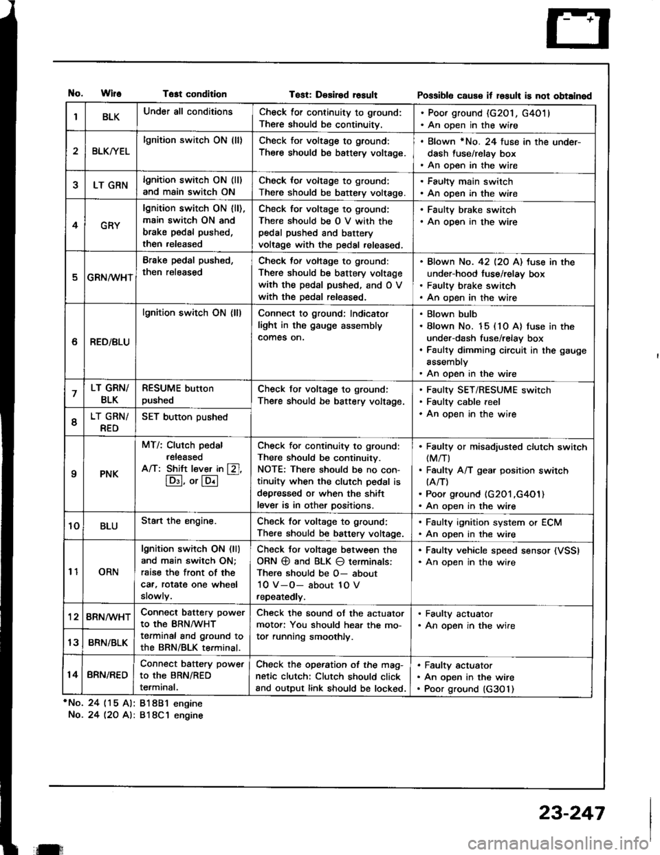
IBLKUnder all conditionsCheck for continuity to ground:
There should be continuitv.
. Poor ground (G201, G4011. An open in the wire
2BLKryEL
lgnition switch ON (ll)Check for voltage to ground:
There should be battery voltage.
. Blown rNo. 24 fuse in the under-
dash fuse/relay box. An open in the wire
5LT GRNlgnition switch ON (ll)
and main switch ON
Check for voltage to ground:
There should be battery volt€ge.
. Faulty main switch. An open in the wire
4GRY
lgnition switch ON lll),main switch ON and
brake pedal pushed,
then released
Check for voltage to g,ound;
There should be O V with thepedal pushed and battery
voltage with the pedal released,
. Faulty brake switch. An open in the wire
GRN/wHT
Brake pedal push€d,
then r€leased
Check tof voltage to ground:
There should be battery voltage
with the pedal pushed, and O V
with the Dedal released.
Blown No. 42 l2O Al tuse in the
under-hood fuse/relay box
Faulty brake switch
An open in the wire
6RED/BLU
lgnition switch ON (ll)Connect to ground; Indicator
light in the gauge assembly
comes on.
Blown bulb
Blown No. 15 (10 A) fuse in the
under-dash fuse/relay box
Faulty dimming circuit in the gauge
assembly
An open in the wire
7LT GRN/
BLK
RESUME button
pushedCheck for voltage to ground:
There should be battery voltage.
Faulty SET/RESUME switch
Faulty cable reel
An open in the wire6LT GRN/
RED
SET button pushed
qPNK
MT/: Clurch pedal
released
A/T: Shift l€ver in [Zl,
lD:I, or lE.l
-
Check for continuity to ground:
There should be continuity.
NOTE: There should be no con-
tinuity when the clutch pedal is
depressed or when the shift
lever is in other positions.
Faulty or misadiusted clutch switch(M/T)
Faulty A/T gear position switch(A/T)
Poor ground (G201 ,G4O1)An open in the wire
10BLUStart the engine.Chsck for voltage to ground:
There should be battery voltage.
. Faulty ignition system or ECM. An open in the wire
11ORN
lgnition switch ON (ll)
and main switch ON;
rsise the front of the
car, rotat€ one wheel
slowly.
Check Jor voltage between the
ORN @ and BLK O terminals:
There should be O- about
10 V-O- about 1O V
repeatedly.
. Faulty vehicle speed sensor (VSSI. An oDen in the wire
'128RN/WHTConnect battery power
to the BRN/WHT
terminal and ground to
the BRN/BLK terminal.
Check the sound of the actuator
motor: You should hear the mo-
tor running smoothly.
. Faulty actuator. An opsn in the wire
13BRN/BLK
14BRN/RED
Connect battery power
to the BRN/RED
terminal.
Check the operation of the mag-
netic clutch: Clutch should click
and output link should be locked.
Faulty actuator
An open in the wire
Poor ground (G3O 1)
il:
23-247
Page 1354 of 1413
Cruise Gontrol
Set/Resume Switch Test/Replacement
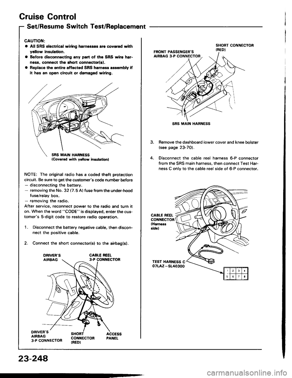
CAUTION:
a All SRS ol6ct cal widng herne$a3 err covorod with
y6llow insulation.
a Bototo disconnecting any part ot tho SRS wiro h8r-
n6sa, connoct tho ghort connector(sl,
a Rsplaco the antire aftected SRS harness arsombly if
it has an op6n chcuit or damagod wiring.
NOTE: The original radio has a coded theft protection
circuit, Be sure to get the customer's code number befor€- disconnecting the battery.- removing the No. 32 (7.5 A) fuse from the under-hood
fuse/relay box.- removing the radio.
Afte, service, reconnect power to the radio and turn it
on. When the word "CODE" is displayed, enter the cus-
tomer's s-digit code to restore radio op€ration.
1 . Disconnect the battery negative cable, then discon-
nect the Dositive cable.
2. Connect the short connector(s) to the airbag(s).
DRIVER'SAIRBAG3-P CONNECTOR
SHORT ACCESSCON]TECTON PANEL(REDI
23-248
SRS MAIN HARNESS
3. Remove the dashboard lower cover and knee bolster(see page 23-70).
4. Oisconnect the cable reel harness 6-P connector
from the SRS main harness, then connect Test Har-
ness C onlv to the cable reel side of 6-P connector.
CABLE REELCONNECTORlHlrnoa!Eidol
Page 1359 of 1413
1.
2.
3.
Actuator Assembly Test
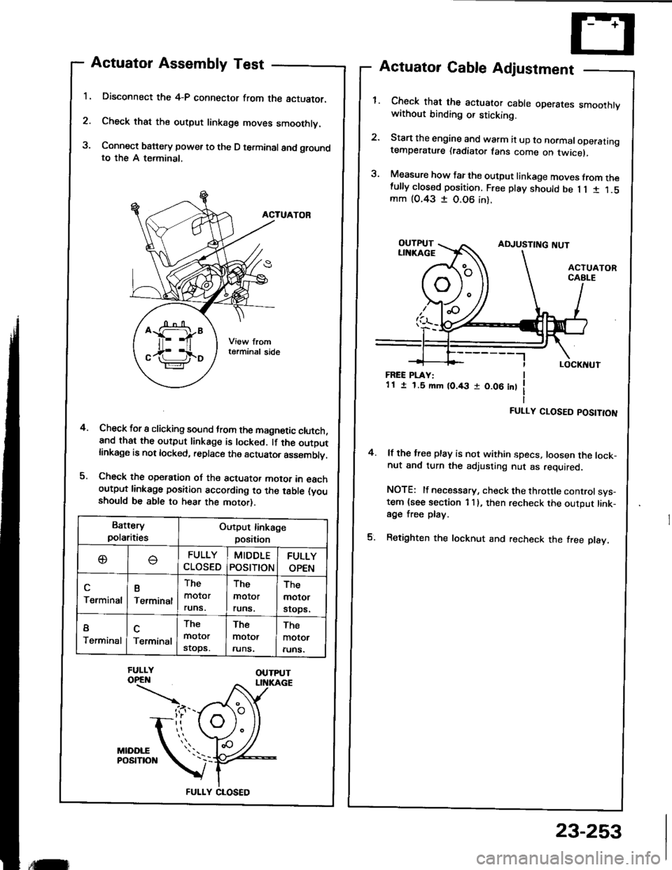
Disconnect the 4-P connector from the actuator.
Check that the output linkage moves smoothly.
Connect battery power to the D terminal and groundto the A terminal,
ACTUATOR
Check for I clicking sound trom the magnetic clutch,and that the output linkage is locked. lf the outDutlinkage is not locked, replace the actuator asssmblv.
Check the operation oJ the actuator motor in eachoutput linkago position according to the table (youshould be able to hear the motor).
Actuator Cable Adjustment
Check that the actuator cable operares smoothtvwithout binding or sticking.
Start the engine and warm it up to normaloperatingtemperature (radiator fans come on twicel,
Measure how far the output linkage moves from thefully closed position. Free play should be 1 1 1 1.5mm (O.43 I 0.06 in).
4.
FREE PLAY:1 1 I 1.5 mm (0.43 r 0.06 int
FULLY CLOSED POSITION
4. lf the free play is not within specs, loosen the lock-nut and turn the adjusting nut as required.
NOTE: lf necessary, check the throttle controlsys-tem {see section 1 I }, then recheck the output link-age free play.
5. Retighten the locknut and recheck the free play.
Battery
polaritiesOutput linkage
position
oFULLY
CLOSED
MIDDLE
POStTtON
FULLY
OPEN
Terminal
B
Terminal
The
molor
runs.
The
molor
runs.
The
molor
srops.
I
TerminalTerminal
The
motor
stops.
The
motor
runs.
The
motor
runs.
FULLY CLOSED
,tilr
23-253
Page 1366 of 1413
Wipers/Washers
Windshield Wiper Motor Test
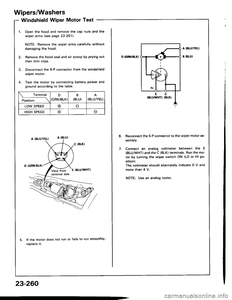
Open the hood and remove the cap nuts and the
wiper arms (see page 23-261).
NOTE: Remove the wiper arms carefully without
damaging the hood.
Remove the hood seal and air scoop by prying out
their trim clips.
Disconnect the 5-P connector from the windshield
wiper motor.
Test the motor by connecting battery power and
ground according to the table.
lf the motor does not run or fails to run smoothly,
replace rr.
Terminal
Pi"i,i""---\
D
{GRN/BLK)
B
{8LU)(BLU/YEL}
LOW SPEED@
HIGH SPEED@
23-260
D IGB /BLK)
A SLUTYEL}
B (BLUI
Reconnect the 5-P connector to the wiper motor as-
sembly.
Connect an analog voltmeter between the E
{BLU/wHT) and the C (BLK) terminals. Run the mo-
tor by turning the wipet switch ON (LO or Hl po-
sition).
The voltmeter should alternately indicate O V and
more than 4 V.
NOTE: Use an analog tester.
Page 1368 of 1413
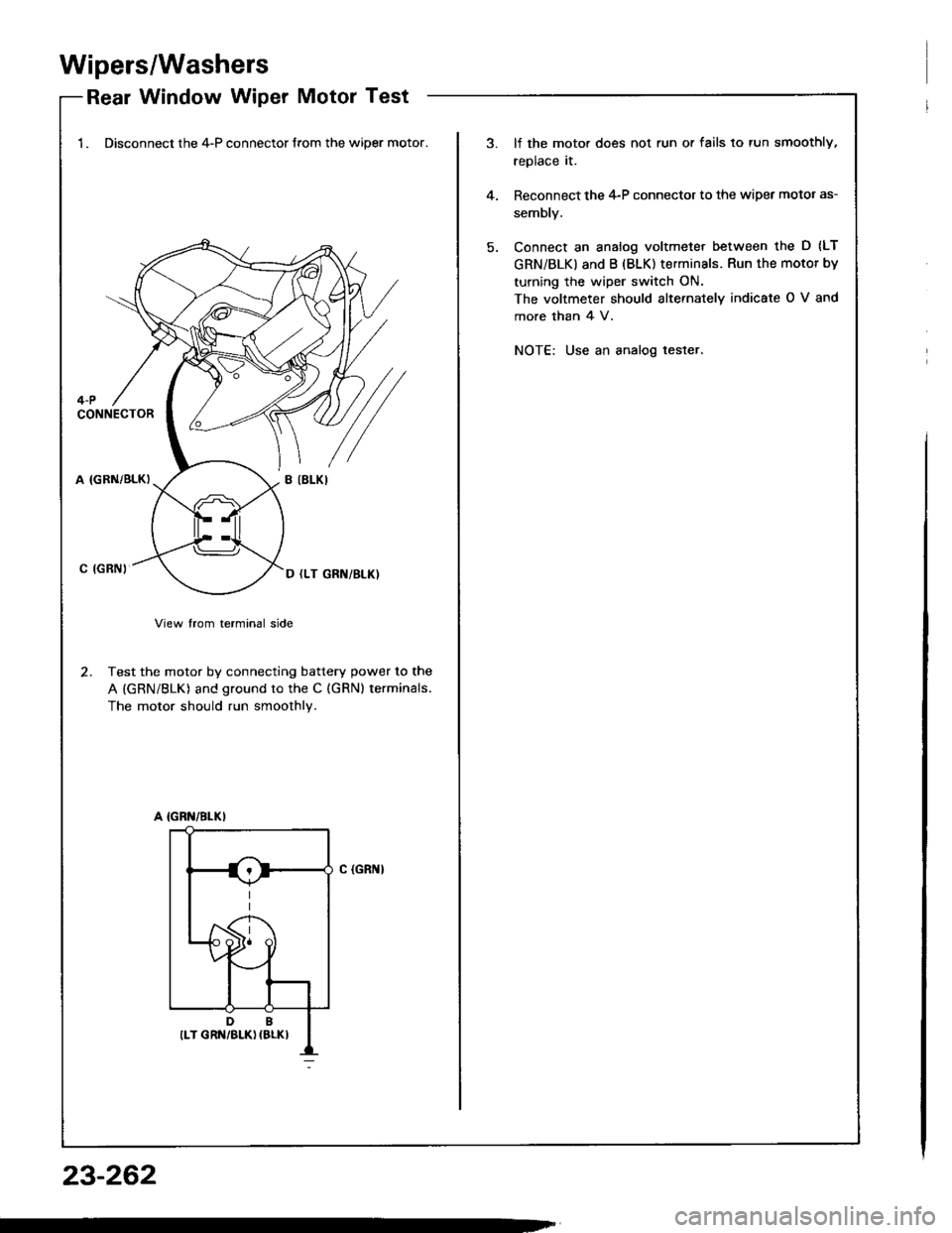
Wipers/Washers
Rear Window Wiper Motor Test-Keal wlnqow wlper |Yloror I esr
1. Disconnect the 4-P connector from the wiper motor.lf the moto. does not run or fails to tun smoothly,
replace it.
Reconnect the 4-P connector to the wipet motor as-
sembly.
Connect an analog voltmeter between the D (LT
GRN/BLKI and B (BLK) terminals. Run the motor by
turning the wiper switch ON.
The voltmeter should slternately indicate O V and
more than 4 V.
NOT€: Use an analog tester.
4.
4-PCONNECTOR
A (GBN/BLK)
C IGRNI
View trom terminal side
2. Test the motor by connecting battery power to the
A (GRN/BLK) and ground to the C (GRN) terminals.
The motor should run smoothly.
C (GRI{}
23-262
Page 1369 of 1413
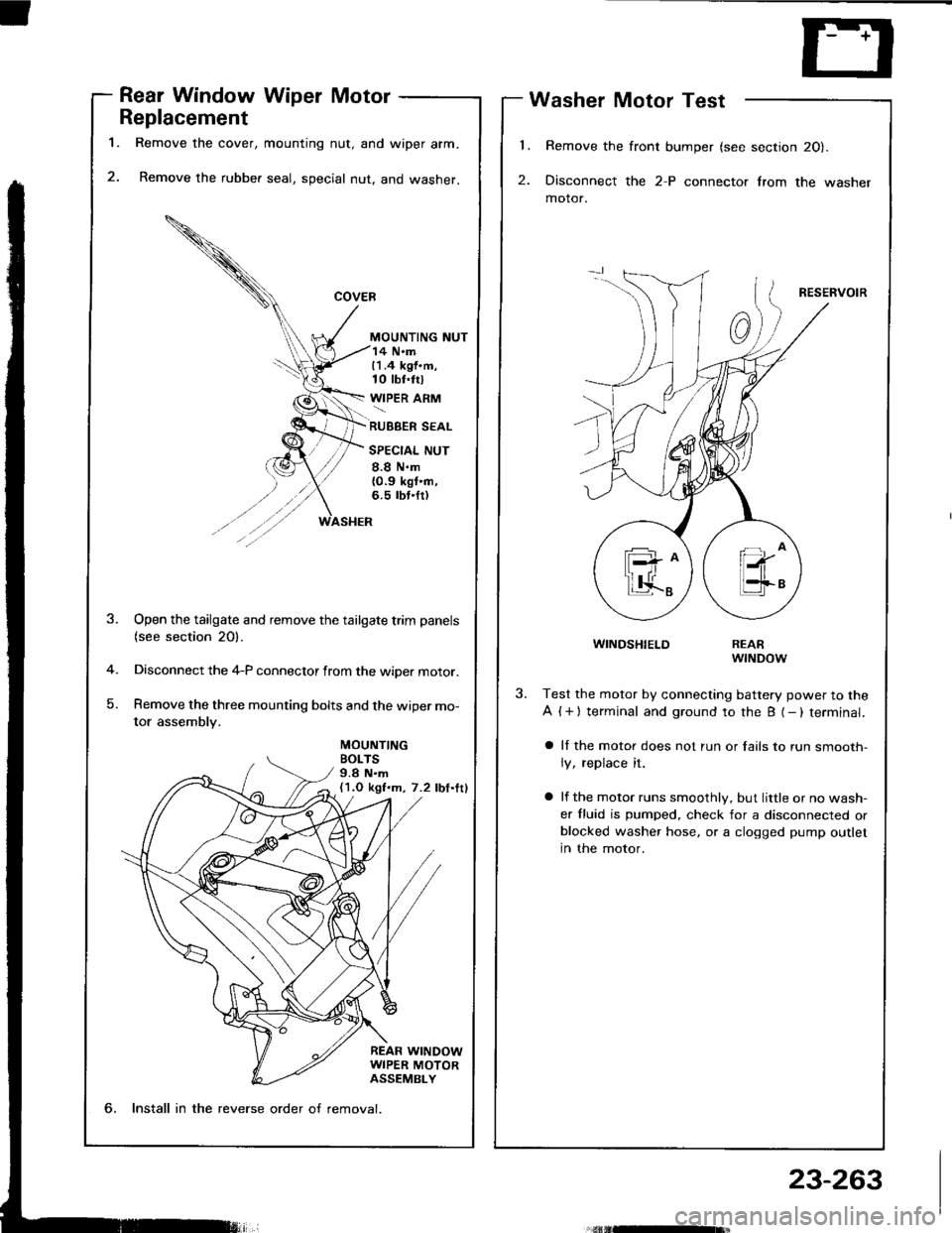
l.
2.
1.
Rear Window Wiper Motor
Replacement
Remove the cover, mounting nut, and wiper arm.
Remove the rubber seal, special nut, and washer.
MOUNTING NUT
Washer Motor Test
Remove the front bumper (see section 20).
Disconnect the 2-P connector lrom the washer
motor.
RESERVOIR
WINDSHIELD
14 N.m11.4 kgf.m,10 tbt.trl
WIPER ARM
RUBBER SEAL
SPECIAL NUT
8.8 N.m{0.9 kgt'n,6.5 rbt.fr)
MOUNTINGBOLTS9.8 N.m(1.O kgf.m, 7.2 lbf.ttl
-4
)
Open the tailgate and remove the tailgate trim panels(see section 20).
Disconnect the 4-P connector from the wiper motor.
Remove the three mounting bolts and the wiper mo-
tor assembly.
REARwrNDow
Test the motor by connecting battery power to the
A ( + ) terminal and ground to the B (- ) terminal.
a ll the motor does not run or fails to run smooth-
ly, replace it.
a lf the motor runs smoothly, but little or no wash-
er fluid is pumped. check for a disconnected orblocked washer hose, or a clogged pump outlet
in the motor.
6, Install in the reverse order o{ removal.
23-263
Page 1376 of 1413
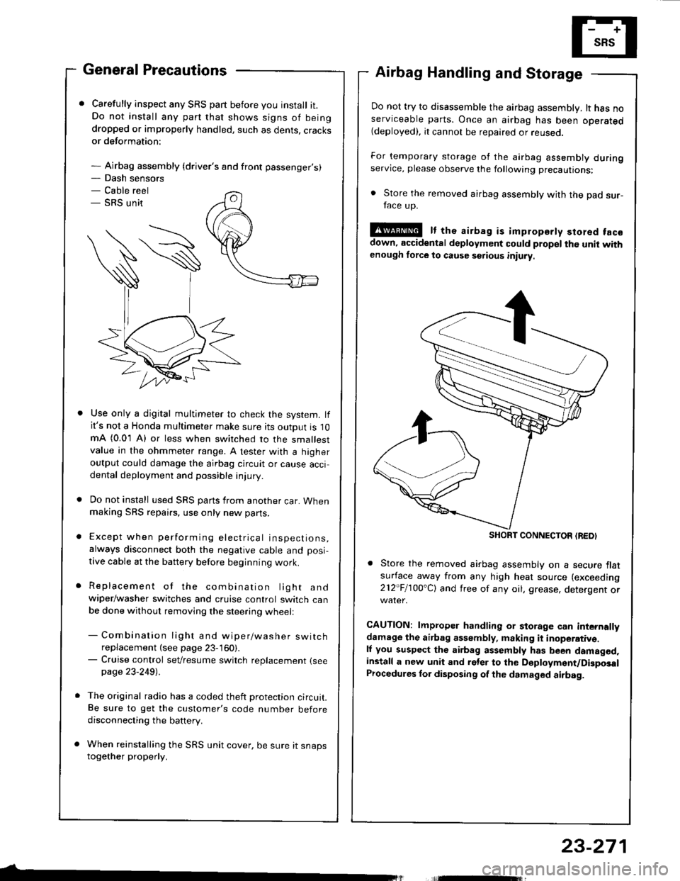
- Dash sensors- Cable reel- SRS unit
General Precautions
Carefully inspect any SRS part before you install it.Do not install any part that shows signs of beingdropped or improperly handled, such as dents, cracksor deformation:
- Airbag assembly {driver's and front passenger's)
Airbag Handling and Storage
Do not try to disassemble the airbag assembly. lt has noserviceable parts. Once an airbag has been operated(deployed), it cannot be repaired or reuseo.
For temporary storage of the airbag assembly duringservice, please observe the following precautions:
. Store the removed airbag assembly with the pad sur-face up.
!@ It the airbag is impropsrty stored facsdown, accidental deployment could propel the unit withenough force to cause setious iniury
Store the removed airbag assembly on a secure flatsufface away from any high heat source (exceeding
212"Fl1OO'Cl and free of any oil. grease, detergent or
CAUTION: lmproper handling or storage can internallydamage the airbag assembly, making it inoperativ€.ll you suspect the airbag assembly has been damagod,install a new unit and rgler to the Deployment/DigposalProcedures lor disposing of the dsmaged airbag.
Use only a digital multimeter to check the system. lfit's not a Honda multimeter make sure its output is 10mA (0.01 A) or less when switched to the smallestvalue in the ohmmeter range. A tester with a higheroutput could damage the airbag circuit or cause accidental deployment and possible injury.
Do not install used SRS parts from another car. Whenmaking SRS repai.s, use only new pans.
Except when performing electrical inspections,always disconnect both the negative cable and posi-
tive cable at the battery before beginning work.
Replacement of the combination light andwiper/washer switches and cruise control switch canbe done without removing the steering wheell
- Combination light and wiper/washer switchreplacement (see page 23-160).- Cruise control sevresume switch replacement {seepage 23-2491 .
The original radio has a coded theft protection circuit.Be sure to get the customer's code number beforedisconnecting the battery.
When reinstalling the SRS unit cover, be sure it snapstogether properly.
SHORT CONNECTON {REDI
23-271
Page 1377 of 1413
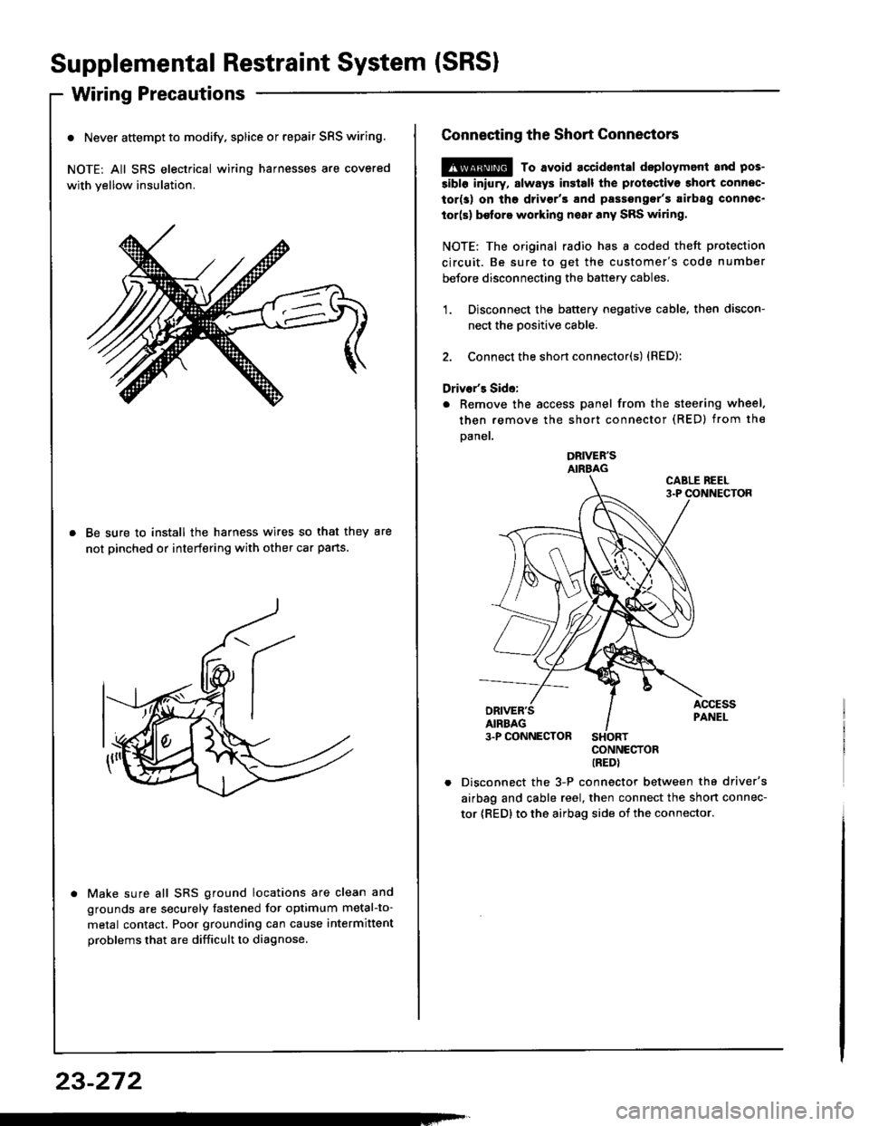
Supplemental Restraint System (SRSI
Wiring Precautions
o Never attempt to modify. splice or repair SRS wiring.
NOTE: All SRS electrical wiring harnesses are covered
with yellow insulation.
Be sure to install the harness wires so that they are
not pinched or interfering with other car pans.
Make sure all SRS ground locations are clean and
grounds are securely fastened for optimum metal-to-
metal contact. Poor grounding can cause intermittent
problems that are difficult to diagnose.
23-272
Connecting the Short Connectors
@ To avoid accident8l deploymont and pos-
5ibl6 iniury, slways insiall the protectiva short connec-
tor(s) on tho drivgr'3 and passengor's airbag connec.
tor(s) be{ore working noar any SRS wiring.
NOTE: The original radio has I coded theft protection
circuit. Be sure to get the customer's code number
before disconnecting the battery cables.
1. Disconnect the battery negative cable. then discon-
nect the Dositive cable.
2. Connect the short connector(s) {RED):
Driver's Side:
. Remove the access panel from the steering wheel.
then remove the short connector (RED) from the
Daner.
DRIVER'SAIRBAG
CONNECTORIREDI
Disconnect the 3-P connector between the driver's
airbag and cable reel, then connect the short connec-
tor {RED} to the airbag side oi the connector.