Page 1261 of 1413
Gircuit Diagram (Canadal
BATTERY
G"*
UNOER_HOOD FUSEiRETAY 8OX
coMBrNAtor{ rcHrswnc
-il w
| '.=r" I
ll'L I I
I I *o\." l-'li' ;- ;j
I LI
"- r.r-,9 "orr
I
d "
L
RED/BLU REO/}VHT RED,ll
I UNDEN-DASH II FUSEiIEI,AY 8OX I
tl
L-J
t'GRN
/d\BATtG2\9-l
rGNrTrot{swITcH
No.2lfl0A)\I
No.l9|l04]Jm.tr (
t10A) ttt
I
No.l6{7.54}
tl
i,"#
llrrff li'rrt,
RED/GRtIIBLU REOr'TVHTINED/B
V
WHTTYEL
. DASH LGHTS BRIGHTNESSCOI{TROLLER. DASH I-IGHTS. PARKING I-GHIS. TAII,LIGHTS. UCENSE N"AT€ LIGI{TS
I a-rneonru jllA/Vr l"o I f# wxrintoRED/GRI{ +\{H I
DAYTIME RUNNINGUGI{TS RESISTOR
IRED/GRN
Hr I r-01651,1/) | l55W)HIt85W)LOt55Wl
HIGH BEAMINOICATORUGHTfl.4W
I
RIGHTHEADLIGHTPARKIIIGBRAKEsw{TcH
23-155
Page 1263 of 1413
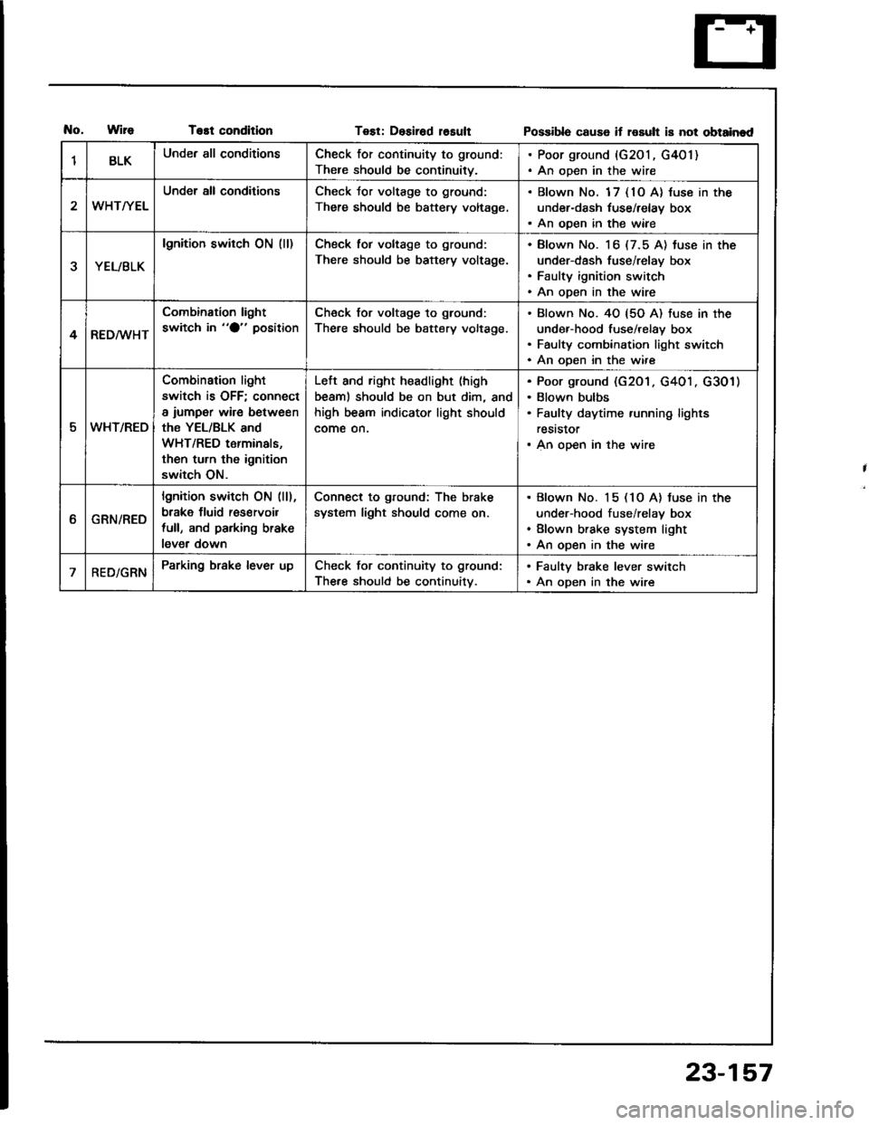
T€st conditionTest: Desirad losultPossibla cause if rosult is not obtainad
1BLKUnder all conditionsCheck for continuity to ground:
There should be continuity.
. Poor ground {G201, G401). An open in the wire
WHT/YEL
Under all conditionsCheck Jor voltage to ground:
There should be battery voltage.
. Blown No. 1 7 { 10 A} luse in the
under-dash tuse/relay box. An ooen in the wiae
YEL/BLK
lgnition switch ON (ll)Check tor voltage to ground:
There should be battery voltage.
Blown No. 16 (7.5 A) tuse in the
under-dash fuse/relay box
Faulty ignition switch
An open in the wire
4RED/WHT
Combination light
switch in "O" positionCheck for voltage to ground:
The.e should be battery voltage.
Blown No. 40 {5O A) fuse in the
under-hood fuse/relay box
Faulty combination light switch
An ooen in the wire
5WHT/REO
Combination light
switch is OFF; connect
a iumper wire between
the YEL/BLK and
WHT/RED terminals,
then turn th6 ignition
switch ON.
Left and right headlight (high
beaml should be on but dim, and
high beam indicator light should
come on.
Poor ground (G201 . G401 . G301)
Blown bulbs
Faulty daytime running lights
reststor
An open in the wire
ttGRN/RED
lgnition switch ON (ll),
brake fluid res€rvoil
full, and parking brake
lever down
Connect to ground: The brake
system light should come on.
Blown No. 15 (1O A) tuse in the
under-hood fuse/relay box
Blown brake system light
An open in the wire
RED/GRNParking brake lever upCheck for continuity to ground:
The.e should be continuitv.
. Faulty brake lever switch. An open in the wire
23-157
Page 1277 of 1413
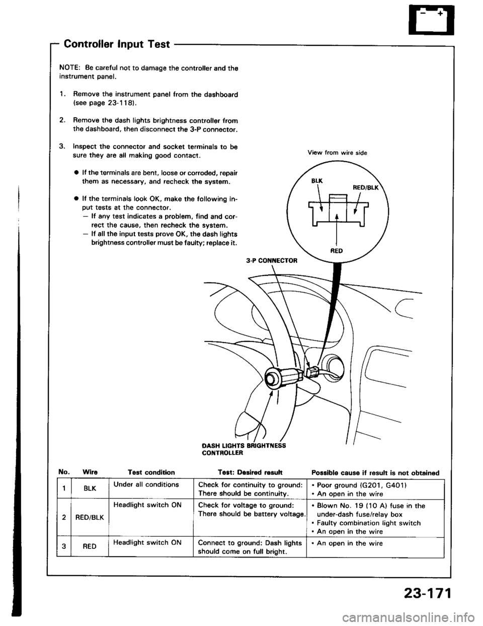
Controller Input Test
NOTE: 8e careful not to damage the controller and the
instrument panal.
1. Remove the instrument panel lrom the dsshboard
{see page 23-1181.
2. Remove the dash lights b.ightness controller {rom
the dashboard. then disconnect the 3-P connector.
Inspect the connector and socket terminals to be
sure they are all making good contact.
a lf the terminals are bent. loose o. corroded, repsir
them as necessary, and recheck the system.
a It the terminals look OK, make the tollowing in-
Dut tests at the connector.- lf any test indicates a problem, find and cor-
rect the cause, then recheck the system.- lf all the input tests prove OK, the dash lights
brightness controller must be faulty; replace it.
View from whe side
Possible causo it resull is not obtained
3-P CON[{ECTOR
OASH LIGHTSCOI{TROLIER
WireTost conditionTogt: Dasired resuh
1BLKUnder all conditionsCheck for continuity to ground:
There should be continuitv.
. Poor ground (G20 l , G4O1). An open in the wire
RED/BLK
Headlight switch ONCheck Jor voltage to ground:
There should be battery voltage.
Blown No. 19 (1O A) tuse in the
under-dash fuse/relay box
Faulty combination light switch
An open in the wire
aREDHeadlight switch ONConnect to ground: Dash lights
should come on full bright.
. An open in the wire
23-171
Page 1292 of 1413
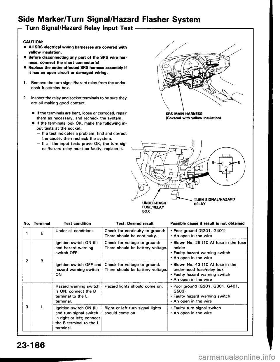
Side Marker/Turn Signal/Hazard Flasher System
Turn Signal/Hazard Relay Input Test
CAUTION:
a All SRS electrical wiring harn6ss6s ar€ covered with
yellow insulation.
a B€foro disconn6cting any part of th€ SRS wire har-
noss, connoct tho short connector(s).
a Replaco tho ontiro sftoctod SRS harness ass€mbly it
it has an open circuit or damagod wiring,
I . Remove the turn signal/hazard relay from ths under-
dash Juse/relay box.
2. Inspect the relay and socket terminals to be sure they
are all making good contact.
a It the terminals are bent, loose or coroded, repair
them as necessary, and recheck the system.
a lf the terminals look OK, make the tollowing in-
put tests at the socket.- lf a test indicates a problem, find and correct
the cause, then recheck the system.- lf all the input tests prove OK, the turn sig-
nal/hazard relay must be taulty; replace it.
UI{DEB-DASHFUSE/RELAYBOX
Test: D€sired rosult
SBS MAIN HAR ESS{Covg.ed with yollow inrulltion)
TelminalTeEt conditionPo$iblo causo it fosult is not obtainod
,lEUnder all conditionsCheck for continuity to ground:
There should be continuitv.
. Poor ground (G201 , G4O1). An oDen in the wire
2B
lgnition switch ON (ll)
and hazard warning
switch OFF
Check for voltage to ground:
There should be battery voltage.
Blown No. 26 (10 A) fuse in ths fuse
holder
Faulty hazard warning switch
An open in the wire
lgnition switch OFF and
hazard warning switch
ON
Check for voltage to ground:
There should be battery voltage.
Blown No. 43 (10 Al fuse in the
under-hood fuse/relay box
Faulty hazard warning switch
An ooen in the wire
3
Hazard wa.ning switch
is ON; connect the B
terminal to the L
termrnat.
Hazard lights should come on.Poor ground (G2O1, G3O1, G4O1
G503)
Faulty hazard warning switch
An open in the wire
lgnition switch ON (lll
and turn signal switch
in right or left; connect
the B terminal to the L
terminal.
Right or left turn signal lights
should come on.
. Faulty turn signal switch. An open in the wire
23-186
-
Page 1294 of 1413
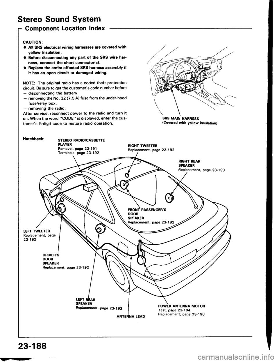
Stereo Sound System
Component Location Index
LEFT TWEETERReplacement, page
23-192
DRIVER'SDOORSPEAKERRepfacement, page 23-192
CAUTION:
a All SRS el€ctrical wlring harneaseE are covered with
yallow insulation.
a Belore dbconnscting any part of the SRS wire har-
nass, connect tho short connector(sl.
a Replace tho entir6 affoctod SRS harn6ss assembly if
it has an opan circuit or damag6d widng.
NOTE: The original radio has a coded theft protection
circuit. Be sure to get the customet's code number belore- disconnecting the battery.- removing th€ No. 32 (7.5 A)tuse from the under-hood
fuse/relay box.- removing the radio.
After service, reconn€ct power to th€ radio and tutn it
on. When the word "CODE" is displaved, enter the cus-
tomer's 5-digit code to restore radio opelation.
Hatchback:STEBEO RADIO/CASSETTEPTAYERRemoval. paoe 23-191Terminals, page 23-192
SBS MAII{ I{ARI{ESS(Covor€d wirh y6llow in3ulationl
LEFTSPEAKER
RIGHT REARSPEAKERReplacement. page 23-193
ANTENNA MOTORTest, page 23-194
DOORSPEAKERRepfacement, page 23-192
23-188
!iltil;s'
Replacemenr. page 23-193
Replacement, page 23-196
Page 1297 of 1413
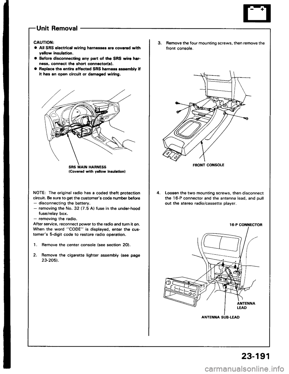
Unit Removal
CAUTION:
a All SRS oloctrical wi ng harn.$.s ara covcrrd withyellow insulation.
a B€toro disconnocting any part ot tho SRS wirc hrr-
nosa, connsct tho short conn6ctol(rl.
a Raplaco the sntirs sttoctod SRS hamoas asacmbly it
it has an opon circuil 01 damagod widng.
NOTE: The original radio has a coded theft protection
circuit. Be sure to get the customer's code number b€lore- disconnecting the battery.- removing the No. 32 (7.5 A) fuse in the under-hood
fuse/relay box.- removing the radio.
After ssrvice, reconnect power to the radio and turn it on.
When the word "CODE" is displayed, enter the cus-
tomer's 5-digit code to restore radio operation.
1. Remove the center console (see section 2O).
2, Remove the cigarette lighter assembly {see page
23-205t.
SRS MAII{ HABNESSFRONT CONSOLE
3.Remove the four mounting screws, then remove the
front console.
Loosen the two mounting screws, then disconnect
the 16-P connector and the antenna lead, and oull
out the stereo .adio/cassette player.
4.
16-P COi{i{ECTOR
ANTENlTA SUB-LEAD
23-191
Page 1300 of 1413
Stereo
Power
Sound
Antenna
System
Motor Test
Remove the quarter trim panel (Hatchback) or trunk
side trim panel (Sedan).
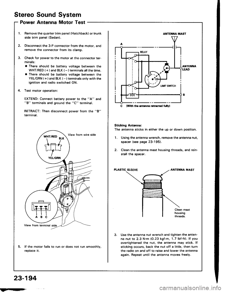
Disconnect the 3-P connector from the motor, and
remove the connector from its clamD.
Check for power to the motor at the connector ter-
minals:
a There should be battery voltage between the
WHT/RED (+l and BLK {-} terminals all thetime.a There should be battery voltage between the
YEL/GRN {+) and BLK (-} terminals onlv with the
ignition and radio switched ON.
Test motor oDeration:
3.
4.
EXTEND: Connect battery power to the "A"
"B" terminals and ground the "C" terminal.
8no
"4"RETRACT: Then disconnect power trom the
terminal,
lf the motor fails to run or does not run smoothlv,
reDtace tr.
*ft'^to
?r*
TIFIT*r'
YEL/GRN
AI{TE T{A MAST
AI{TEI{I{ALEAD
C ftYhh lha lnLnn. r.tr.ci.d t|Ilyl
Sticking Ant6nna:
The antenna sticks in either the up or down position.
1.Using the antenna wrench, remove the antenna nut,
spacer (see page 23-195).
Clean the antenna mast housing threads, and rein-
stall the soacer.
PLASTIC SLEEVEAIITENNA MAST
Cloan masthousingthroads.
Use the antenna nut wrench and tighten the anten-
na nut to 2.3 N.m (0.23 kgf-m, 1.7 lbf-tt). lJ you
overtightened the nut. the antenna may stick. lf
sticking occurs, back the nut off a little, then turn
the radio on and off to raise and lower the antenna
again. Repeat until the antenna moves treely.
23-194
fmft,
Page 1307 of 1413
Switch Test
CAUTION:
a All SRS el6ctrical wiring harnossos are covarod withyellow inaulation.
a Beforo disconnecting any pan ot the SRS wire har-neaa, connoct ths short connector(s).a Roplace the entil€ afloctod SRS harne$ a$6mbly ifit has an open circuit or dsmagad wlring.
NOTE; The original radio has a coded theft protection
circuit. Be sure to get the customer's code number before- disconnecting the battery.- removing the No. 32 {7.5 A) fuse lrom the under-hoodtuse/relav box.- removing the radio.
After service, reconnect power to the radio and turn iton. When the word "CODE" is displayed, enter the cus-tomer's 5-digit code to restore radio operation.
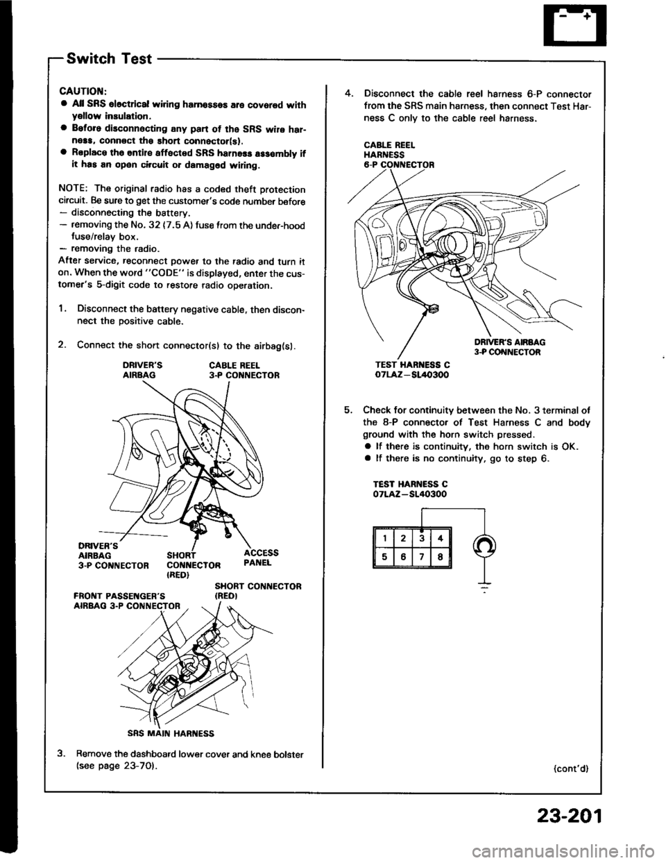
1. Disconnect the battery negative cable, then discon-nect the positive cable.
2. Connect the short connector(sl to the airbag(sl.
DRIVER'SAIRBAGCABLE REEL3.P CO NECTOR
DRIVER'SAIRBAG3-PCO'TNECTOR COI{NECTOR{RED}
ACCESSPAI{EL
SHORT CONTIECTOR{REO}
Remove the dashboatd lower cover and kne€(see page 23-701.
5.
4. Disconnect the cable reel harness 6-P connector
from the SRS main harness, then connect Test Har-
ness C onlv to the cable reel harness.
CABLE REELHARNESS
TEST HAR ESS CoTLAz - SL/l{,3OO
Check for continuity between the No, 3 terminal ot
the 8-P connector of Test Harness C and body
ground with the horn switch pressed.
a lf there is continuity, the horn switch is OK.a lf there is no continuity, go to step 6.
TEST HARNESS COTLAZ-SI/I()3OO
(cont'd)
bolster
23-201