Page 1206 of 1413

Charging System
Troubleshooting
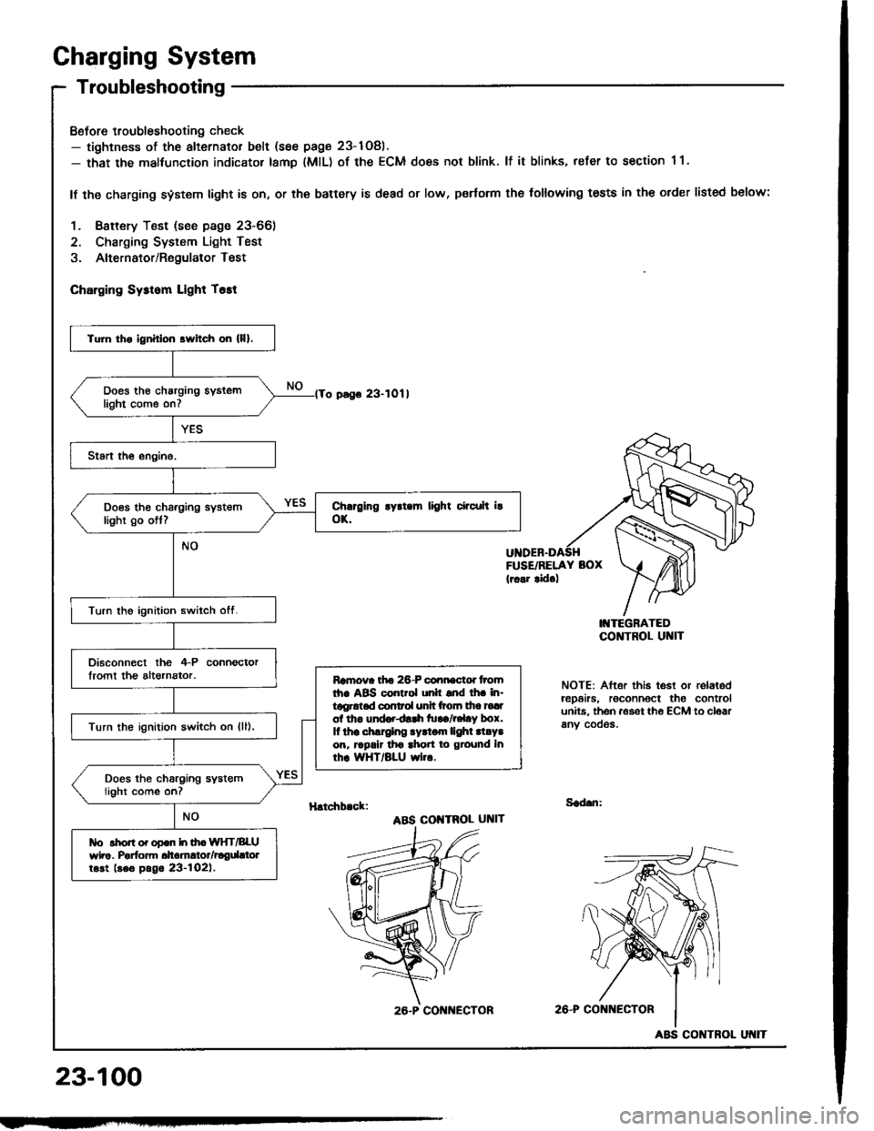
Bofore troubleshooting check- tightness of the alternator belt (see page 23-1Og).- that the malfunction indicator tamp lMlL) of the ECM does not blink. lf it blinks, refer to section 1 1.
lf the charging system light is on, or th€ battery is dead or low, p€rtorm the following tests in the order listed below:
1. Baftery Test (see page 23-66)
2. Charging System Light Test
3. Alternator/RegulatorTest
ChErging Sysrom Light T6tt
o pago 23-1011
FUSE/RELAY BOX(r..r tid.)
I'{TEGRATEDCO]TTROL UI{IT
NOTE: After this test or relaledrep6irs, roconnoct the controlunits. th6n aoset th€ ECM to cloarany cooos.
H.tchb.ck:Sad.n:
ABS COI{TROL UNIT
2A-P CONi{ECTOR
23-100
Tu]n tho ignhlon srvitch on (lll.
Does th€ charging syslemlight come on7
Does tho charging systemlight go ott?
Turn the ignition switch otf.
Disconnect the 4-P connoctorlromt th€ altornator.Ramova tfto 26-P connactd tromth. ABS control unh snd lh. in-tggrotad conrol unh ttoln tha tadol tho und..dlrh tu!a/r.l.y box.It thr .hlrglng .yrtom lighl .l.Y.on, rrpalr tho ahon to ground Inrhr WHT/BLU wi...
Turn the ignition switch on {ll),
Does the charging systemlight come on?
tlo rhon o. opon h ih. WIfT/BLUwho. Porfom dtomrtor/rogdttolrost beo pag. 23-l02l.
26.P CON ECTOR
ABS CONTROL
Page 1207 of 1413
lFrom page 23-10O)'No. 24 (15 A): 818B'lNo. 24 (20 A): 818C1ongrneengine
Turn the ignition switch ott.
Check fuse *No. 24 in the under-dash tuse/relay bor.
Disconnect the 4-P connectorIrom the alternator.
Turn the ignition switch on {ll).
Ch6ck forvoltago between tho lGterminal (BLK/YEL wire) of rho il-Pconnector and body ground.
ls there battery voltage?Rgp.i. op.n in th. BLK|'EL wiro.
Ground the WHT/BLU wire at theL terminal ot the 4-P connector.
Chock for ! blown chrrging ry3-rom llghr bulb. It rh. butb i! oK,ropair open in lho IiYHT/BLU wiro.
Does the charging system lightcome on?
wirg sideL IWHT/BLUI
(cont'd)
23-101
Page 1208 of 1413

Charging System
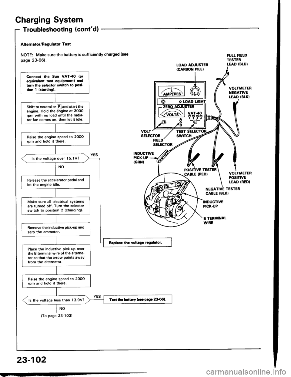
Altornator/Regulator Test
NOTE; Mske sure the battery is sufficiently chargod (sa€
page 23-66).
NO
tropagezJ-ruJ,
O IOAD
VOLTTESTSELECTONswlTcH
II{DUCTIVE
FULL FIELDTESTEBLEAD (BLUILOAD ADJUSTERICARBON PILE)
FICK.I.|PIGR '
VOLTMETERt{EGATIVELEAD (8LK}
VOLTMETERPOStTtVELEAD IREDI
EGATIVE TESTER
CABLE (BLKI
INDUCTIVEPICK.UP
B TERMI]TALWIRE
23-102
Connoct tho Sun VAT4O {otooulvslont lgrt equipmonl) andtum tho s6l6ctor rwitch ro posi_
tion I |rtarting).
shift to neurralorlPland start theengino. Hold the ;;gine at 3oO0rpm wiih no load until the radia_
tor lan com€s on. then let it idle.
Raise the engine speed to 2OOOrom and hold il there.
ls lhe voltage over 15.1V?
Release the accelerator pedal andlet the engino idle.
Make sure all electrical systemsare turned otf. Turn the selectorswilch to position 2 (charging).
Remove the inductive pick-up and
zero the ammeter.
Place the inductive pick-uP overthe B terminalwire oI the altgrna-tor so that the arow Doints awaytrom the alternator.
Raise the engins speed lo 20OOrpm and hold it there.
T..t itr b.ttry (.- 9|e. 8€Al.ls the voltage less than 13.9V?
Page 1209 of 1413
(From page 23-1021
Apply a load wirh the VA'-4O un-til the battery voltage drops to be-tween 12- 13.5 V.
ls the amperage 60 A or more?
With the engine spe6d still at2OOO rpm, full-tield the altemalor.
Toat rnd rooalr d|e dtomEtor {soopsg.. 23-104 to 23-tO7).
Turn the ignition switch off; thenturn at on again.
Disconnocl lhe 4-P connectorIrom the altornator.
Check lor voltage between the lGterminal (BLK/YEL) and bodyground.
ls there battery vokage?Rop.ii open in tho BLK/YEL wiro.
NOTE; Attach a probe to the VAT-4O full field test lead and insert the orobeinto the full tield sccess hole at the back of the alternator. Switch the field selectorto the "A (Ground)" position momentarily and check amperage reading.
CAUTION: The voltago will ris6 quickly whon the slternator is full-fiolded. Donot allow th€ voltago to oxc66d 18 V 01 it may damage the elect.ical system
REGULATOR
{Locatodthe end cover)
FULL FIELDACCESS HOLE
L IWHT/BLUI
4-P CONNECTOR
IG IBLKATELI
wire side
23-103
Page 1210 of 1413

Charging System
Alternator Replacement
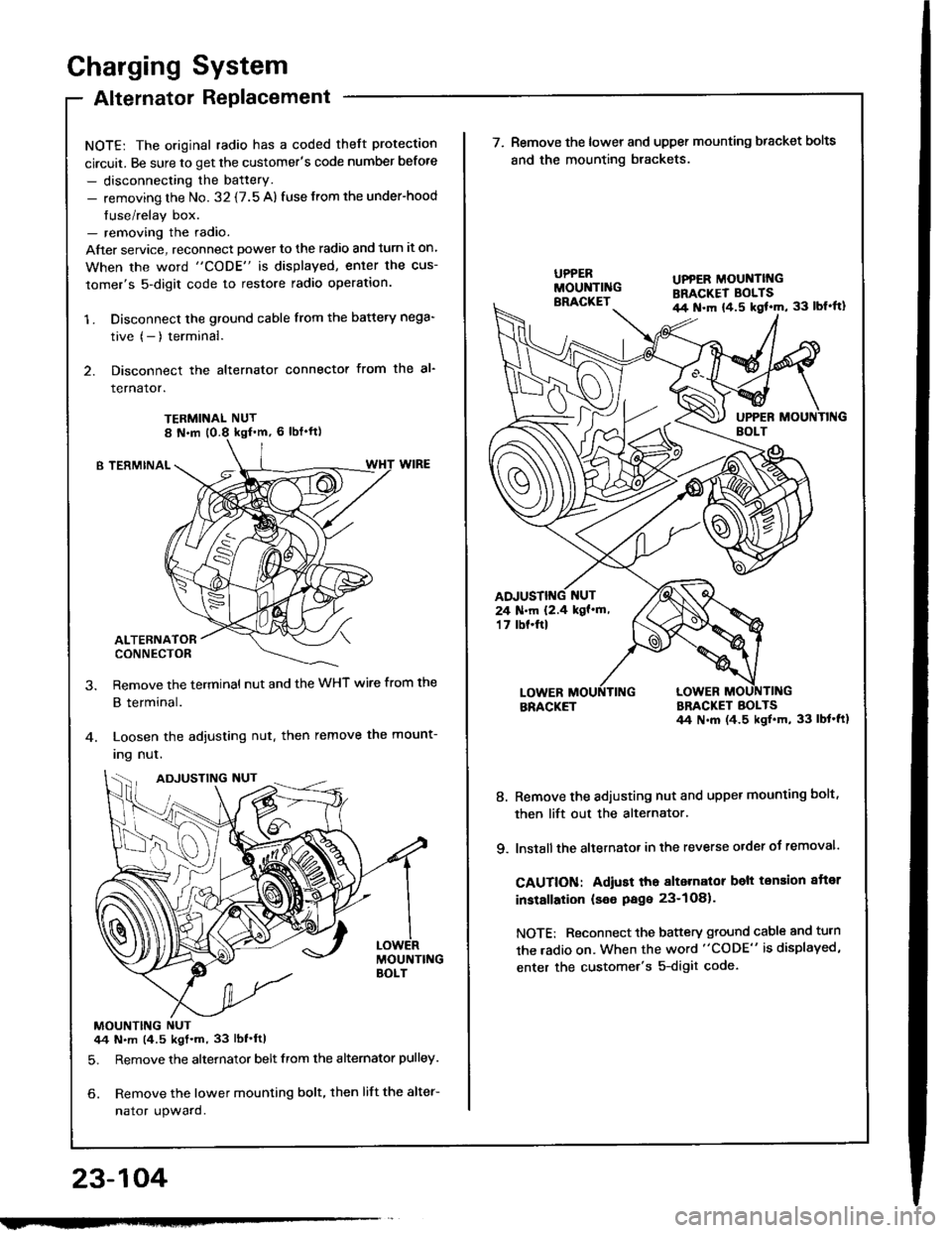
NOTE: The original radio has a coded theft protection
circuit. Be sure to get the customer's code number before
- disconnecting the battery.- removing the No. 32 {7.5 A) fuse from the under-hood
fuse/relay box.- removing the radio.
After service, reconnect powet to the radio and turn it on.
When the word "CODE" is displayed, enler the cus-
tomer's 5-digit code to restore radio operation.
1 . Disconnect the ground cable from the battery nega-
tive (- ) terminal.
2. Disconnect the alternator connector from the al-
rernaror.
TERMINAL NUT
B TERMINAL
ALTERNATORCONNECTOR
Remove the terminal nut and the WHT wire from the
B terminal.
Loosen the adjusting nut. then remove the mount-
Ing nul.
MOUNTING NUT44 N.m (4.5 kgt.m, 33 lbf'ftl
5. Remove the alternator belt from the alternator pulley.
6. Remove the lower mounting bolt, then lift the alter-
nator upward.
23-104
ADJUSTING NUT
w
UPPER MOUNTII{GBRACKET BOLTSil4 N.m {4.5 kgl'm, 33 lbl'ft}
24 N.m 12.4 kgf'm,'t 7 tbf.ftl
\ (^,-(\
\-/ I
7. Remove the lower and upper mounting bracket bolts
and the mounting brackets.
BRACKETBRACKET BOLTS44 N.m (4.5 ksl.m, 33 lbt'ft1
8. Remove the adiusting nut and upper mounting bolt,
then lift out the alternator.
9. lnstall the altetnator in the reverse order of removal.
CAUTION: Adiust tho alternalor belt tension aftor
installation (seo Page 23-1O81.
NOTE: Reconnect the battery ground cable and turn
the radio on. When the word "CODE" is displayed,
enter the customer's 5-digit code.
Page 1218 of 1413
Fan Controls
Fan Motor Test
1. Disconnect the 2-P connector from the fan motor.
2. Test the motot by connecting battery power to the
B terminal, and ground to the A terminal
3. lf the Jan motor fails to run smoothly, replace it.
NOTE: The illustration shows the radiator fan.
Engine Coolant Temperature (ECT)
Switch Test
NOTE: Bleed air from the cooling system atter install-
ing the engine coolant temperature (ECT) switch (see sec-
tion 1O).
1. Remove the ECT switch from the thermostat
housing.
2. Suspend the ECT switch in a container of coolant
as shown.
Heat the coolant and check engine coolanl tempera-
ture with a thermometer.
Check the continuity between the A and B terminals
according to the table:
Terminal
;;,".,"---\
B
Switch
Above 196 2O3"F
{91-95'C)o_-o
Below 181- 189oF
(83-87'C)
23-112
Page 1226 of 1413

Speedometer/Trip Meter/Odometer
Troubleshooting
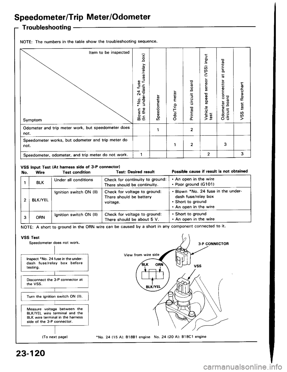
NOTE: The numbers in the table show the troubleshooting sequence.
Item to be inspected
Symptom
-9
;6+*c.r i.(D
zc*f
;59cd)=
E
a
6
E
'iF
o
(L
:lt)a
o
-9
>g
q)
qlv
E
'
E
oo
Odometer and trip meter wotk, but speedometer does
not.12
SDeedometer works, but odometer and trip meter do
nor,1
Speedometer. odometer, and trip meter do not work.
VSS Input Test (At ham€ss side of 3-P connector)
No. Wir6Tost conditionT€st: Desirsd resultPossible cause it result is not obtained
1BLKUnder all conditionsCheck for continuity to ground:
There should be continuity.
. An open in the wire. Poor ground (G1O1)
BLK/YEL
lgnition switch ON (ll)Check tor voltage to ground:
There should be battery
voltage.
Blown *No. 24 fuse in the unde.-
dash tus€/relay box
Short to ground
An open in the wire
ORNlgnition switch ON (ll)Check for voltage to ground:
There should be about 5 V.
. Shon to ground
. An open in the wire
NOTE: A short to ground in the
vSS Tost
Speedometer does not work.
ORN wire can be caused by a short in any component connected to lt.
3-P CONNECTOR
Inspect 'No. 24luse in the under-dash tuse/relay box beloretesting.
Turn the ignition switch ON lll).
Measure voltage between theBLK/YEL wire terminal and the8LK wire terminal in the harnessside of the 3-P connector.
{To next page)
23-120
24 (15 A): 81881 engine No. 24 {20 A): 818C1 engine
Page 1227 of 1413
{From previous page)
Check tor continuity between theBLK terminal and body ground.ls there battery voltage?
Measure voltage between theORN and the BLK wire terminals.Ropair opon belw€onVSS and ground G101.
Ropair opon in tho BLKrYEL wirobotwoen VSS and undor-dsshluse/rolay box.
ls there about 5 V?
Ropair op6n in th6 ORN wire orshon to body ground.Raise the tront of the car and sup-port it with salety stands.
Touch a probe to the ORN wireand connect at to body groundthrough a voltmeter.
Putthe car in neutralwith kev ON.
Slowly rotate one wheel with theother wheel blocked.
Does voltage pulse from O toabout 1O V?Roplac. tho VSS {see page23-1221.
Touch a probe to the ORN wireand connect it to body groundthrough a voltmeter.
Slowly rotate one wheelwith theother wheel blocked.
Ropair opon in th6 OBil wire bo-tween tho VSS and th6 3p.odo-molgt.
Ooes the meter indicatepulsing voltage?
23-121