1994 HONDA INTEGRA battery
[x] Cancel search: batteryPage 1107 of 1413

Electrical
Special Tools
Troubleshooting
Tips and Precautions ................................ 23-3Five-stop Tloubleshooting ..............,...-..-... Z3-sSchematic Symbols ................................_. 23-6wire Color Cod€s ..................................... 23-6Relay and Control Unit Locations
Engine Compartment .........,............ ... --. 23-7Dsshboard and Door ..,,......................... 23-gDashboard and Floor ............................. 23-t OOuaner Panel .....-.....23-12Connector ldentification and WireHarness Routing ........ 23-i 3
Index to Circuits and Systems
Airbag ............... ...-..-... 2g-26sAir Conditioning ....,.. Section 2lAltelnator ......_.............. 23-99Anti-lock Brake Systsm (ABS) Section 19Automatic Transmission Section 14Battery .............. .......... 23-66Chafging System ........... 23-98rCigalstte Lighter .....................-...-......-..-.. Z3-2O4Cfock ................. ..........23-197rcruise Controf .......--..-... 23-242Distributor .................... 23-87Fan Controls ................. 23-1ogFuel and Emissions ... Section 1i*Fuses
Under-dash Fuse/Relay Box ................... 23-48Undor-hood ABS Fuse/Retay Box ............ 23-51Under-hood Fuse/Relay Box,.................. 23-52rGauges
Engine Coolant Temperature {ECT)Gauge ................ ..23-126Fuef cauge ............... 2g-123'Gauge Assembly ....--.23-113Speedometer .....-...,,. 23-114Tachometer .....,.....-.. 23-114Ground Distribution ........ 23-60Heater ,,,........,.... ..... Section 2lrHorn ................. ........... 23-199*fgnition Switch ............. 23-70fgnition Syst6m .......-..-.. 23-A7lgnition Timing .............. 23-89Indicator Lights"A/T Gear Position .............. ................... 23-1 32B1ak6 System ...,..,..-.23-127Engine Oil Pressura .............................. _ 23-1 51Low Fuel ............ ......23-125Malfunction Indicator Lamp {MlL} ...,,. Section I l
tfnteglated Control Unit ...29-144*lnterlock System ...................................... 23-1 3gLights, Exteriol
Back-up Lights ........... 23-179Brake Lights .............. 23-t8ltDaytime Running Lights {Csnada} ........... 23-156Front Palking Lights ............................. 23-1 65Flont Side Marker Lights ....................... 23-165Front Turn Signal Lights ........................ 23-1 65*Hazard Warning Lights .........................- 2g-1A4Headlights ................. 23-t6tLicense Plate Lights .............................. 23-1 69Taillights(Harchback) .......... 23-166
{Sedan) .............. .. 23-167Lights. Inteliol
Cargo Area Light {Hatchback) ...... -.. -.. -... 23-177Ceifing Light ........-..-.23-175
Dash Lights Blightness Controt .............. 23-t70Glove Box Lighr ................................... 23-1 69Spotfighr ............ ....-.23-174Trunk Light (Sedanl ............... .............. - 23.-177*Lighting Sysrem .......-.-... 23-152:Moonroof ,,.,.......,..,,,,,.-.23-211PGM-FI Systom ........ S€crion 11Power Distribution .,.-..--..23-54Power Door Locks .............,,..................... 23-233Power Mirors ..,..,....-...- 23-216Power Relays ...........,..... 23-68Power Windows ............ 29-222*Rear Window Defogger ........,... ..........,..... - 23-20,6Reminder Systems
Key-in Remindel System ....,.............,.... 23-1 50Lights-on Reminder System ................... 23-l 5f*Maintenance Reminder system ..,,.... -.. - -. 23-.1 2gSeat Belt Reminder System ..................- 23-125*Side Markel/Turn Signal/Hazard
Ffasher System .,..,..-.23.-1A4Spark Pfugs .........-...-..... 23-97Starting System ....,,.....-. 23-73*Stereo Sound System ...,.......................,,.. 23-l gg
Supplemental Restraint System {SRS} ......... 23-265Vehicfe Speed Sensor {VSS) .............--..-.... 23-122*Wiper/Washer Systom ...............--.........-..- Zg-254
rRead SRS pi€cautions on Page 23-271 betore workingin these areas.
-+
Page 1109 of 1413
Troubleshooting
Tips and Precautions
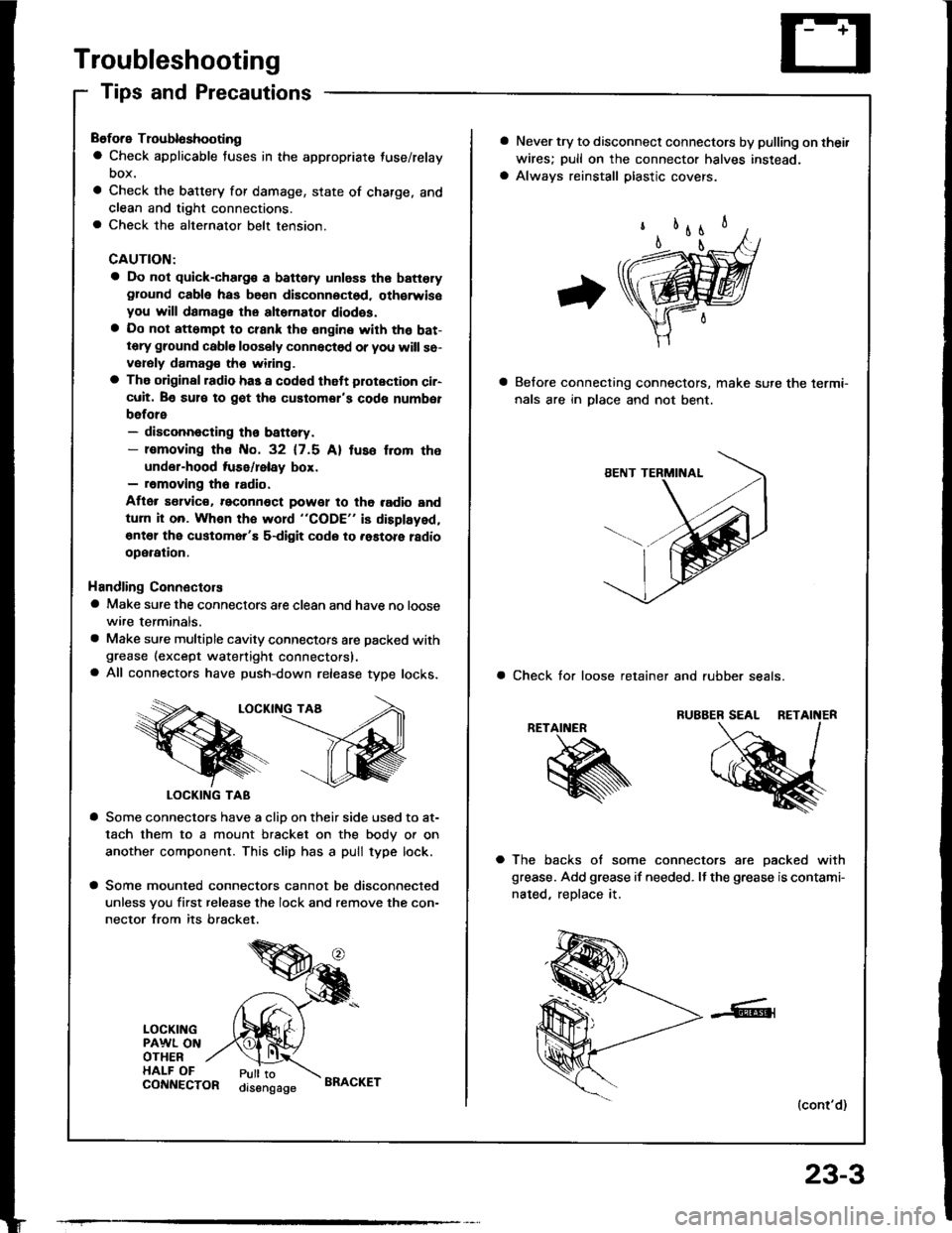
Before Troubloshooting
a Check applicable fuses in the appropriate fuse/relay
DOX.
a Check the battery for damage, state of charge, and
clean and tight connections.a Check the alternator belt tension.
CAUTION:
a Do not quick-charg€ a battery unless the batteryground cabla has be€n disconnoctsd. oth€rwisoyou will damage the alternator diodss.a Do not att6mpt to crank the engine with the bat-tery ground cable loosely connectsd or you will se-vorsly damag€ tho widng.
a The original radio has a codod thatt plotection ci.-cuit. Be sul€ to got tho customor's code numbet
before- disconnecting th€ battery.- lomoving tho No. 32 (7.5 Al tuso f.om the
under-hood tuse/lelay box.- removing tho radio.
Aflor s€lvic€. reconn€ct powet to tho radio and
turn it on. Whon the word "CODE" is displayed,
€nt€l the customer'E s-digit codo to .astore ladio
operation.
Handling Connectors
a Make sure the connectors are clean and have no loose
wire terminals.
a Make sure multiple cavity connectots are packed withgrease (except watertight connectors).a All connectors have push-down release type locks.
LOCKII{G TAA
LOCKING TAB
a Some connectors have a clio on their side used to at-
tach them to a mount bracket on the body or on
another component. This clip has a pull type lock.
a Some mounted connectors cannot be disconnected
unless you first release the lock and remove the con-
nector from its bracket.
LOCKINGPAWL ONOTHERHALF OFPull toorsengageCONNECTORBRACKET
23-3
a Never try to disconnect connectors by pulling on thei.
wires; pull on the connector halves instead.
a Always reinstall plastic covers.
Belore connecting connectors, make sure the lermi-
nals are in Dlace and not bent.
a Check tor loose retainer and rubber seals.
RETAINER
a The backs of some connectors are oacked with
grease. Add grease if needed. It the grease is contami-
nated, reDlace it.
(cont'd)
Page 1112 of 1413
Troubleshooting
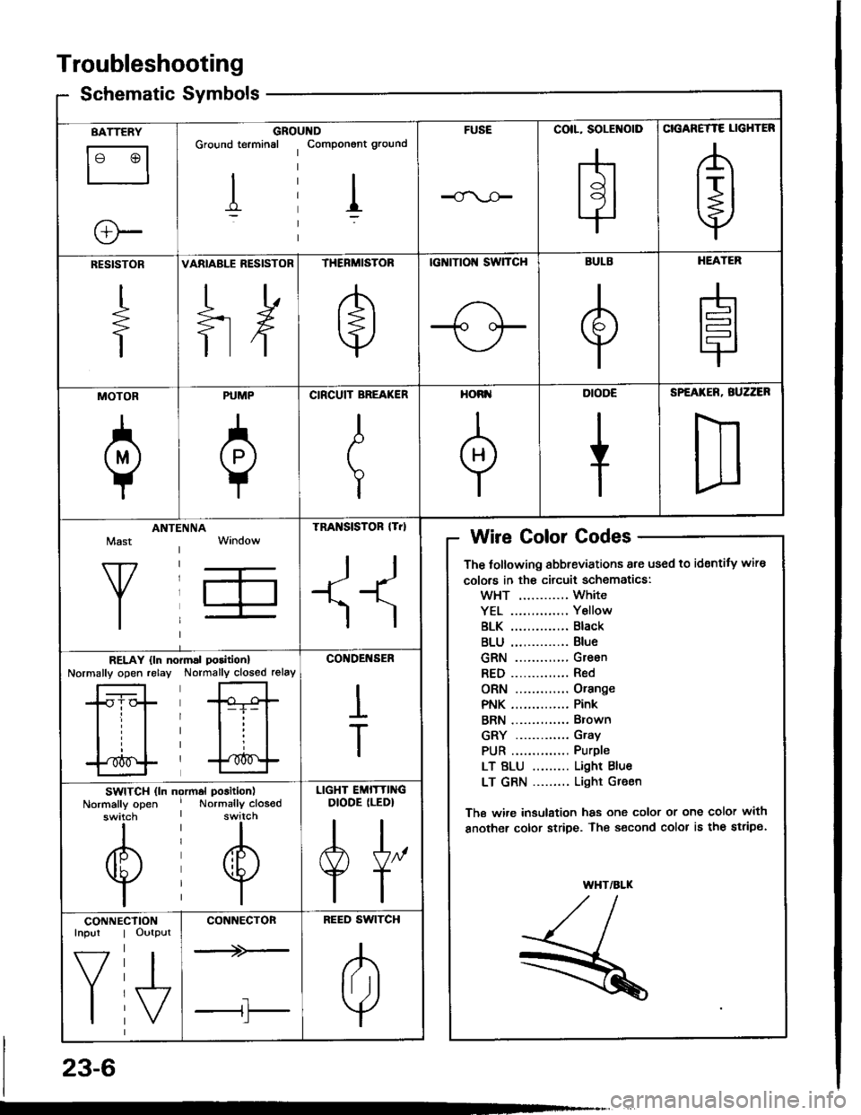
Schematic Symbolsym
BATTERY
le @l
ll
e-
GROIGround terminal
I
,ltDComponont ground
I
FUSECOIL, SOLENOID
H
CIGANETTE LIGHTER
A
t+j
RESISTOR
+
VARIABLE RESISTOR
ilH
THERMISTOR
e
tcNtTtol{ swTcH
-1o oF
BULB
e
HEATER
H
MOTOR
a
PUMP
0
CIRCUIT BREA(ER
I
T
HORI'
+
DIODE
+
SPEATER, BUZZER
D
Mast
Y
ANTIINNATRA SISTOR lTrl
II
Wire Golor Codes
The tollowing abbreviations are used to identity wire
colors in th€ circuit schematics:
wHT ............ White
YEL .............. Y6llow
BLK .............. Black
BLU .............. Blue
GRN ............. Green
RED.............. Red
ORN ............. Orange
PNK .............. Pink
BRN .............. Brown
GRY ............. Gray
PUR .............. Purple
LT BLU ......... Light Blue
LT GRN ......... Light Gr€en
The wi.e insulation has one color or one color with
another color stripe. The s€cond color is the stripe.
WHT/ALK
,/t,/l./l--
R
RELAY {ln noNormally open relayrmal poritionl
Normally closed relay
*Gt-i- |
lll
l'*^f
CO'IDENSER
I
T
SWITCH (ln ngrmal position)
Normally open ' Normally closodswitch I switch
til
@@
lil
LIGHT EMITTINGDIODE (LEDI
A[,
TT
CONNEInpur
f7
I
CTIONOutput
I\/
CONNECTON
--+>-
tl'l
BEED SWITCH
A
lril
Y
23-6
Page 1119 of 1413
Connector ldentification and Wire Harness Routing
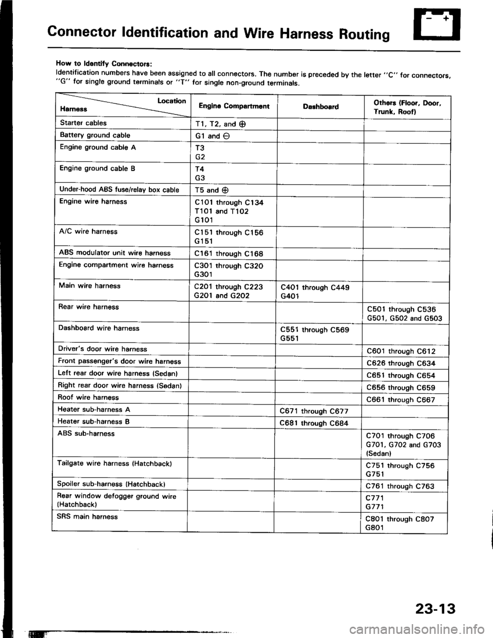
How to ldentity ConnoctolS:
ldentification numbers have been assigned to all connectors. The number is preceded by the letter ,,C,, for connecrors,"G" for single ground terminals ot "f" hr single non-ground terminals.
Location
HamessEngino CompartmontDarhboardOthors (Floor, Door,
Trunk, Rootl
Starter cablesT1, T2, and (E
Battery ground cableG1 and O
Engine ground cable AT3
Engine ground cable BT4
G3
Under-hood ABS fuse/relav box cableT5 and (D
Engine wire harnessC101 through C134
Tl Ol and T102
G 101
A/C wire harnessCl 5'l through C156
G151
ABS modulator unit wir€ harnessC161 through C168
Engine companment wire ha.nessC3O'l through C32O
G301
Main wire hatnessC2O1 through C223
G2Ol and G2O2
C4O1 through C449
G401
Rear wire harnessC501 through C536
G501, G502 and G5O3
DashboSrd wire harnessC551 through C569
G551
Driver's door wire harnessC601 through C612
Front passenger's door wire harnessC626 through C634
Left rear door wire harness (Sedan)C651 through C654
Right rear door wire harness (Sedan)C656 through C659
Roof wire harnessC661 through C667
Heater sub-harness AC671 through C677
Heater sub-hatness BC681 through C684
ABS sub-harnessC7O1 through C7O6
G7O1, G702 and G703(Sedan)
Tailgate wire harness (Hatchback)C751 through C756
Spoiler sub-ha.ness (Hatchback)C761 through C763
Rear window defogger ground wire(Hatchback)c77'l
G771
SRS main harnessC8O1 through C8O7
G801
23-13
Page 1120 of 1413
Gonnector ldentification and Wire Harness Routing
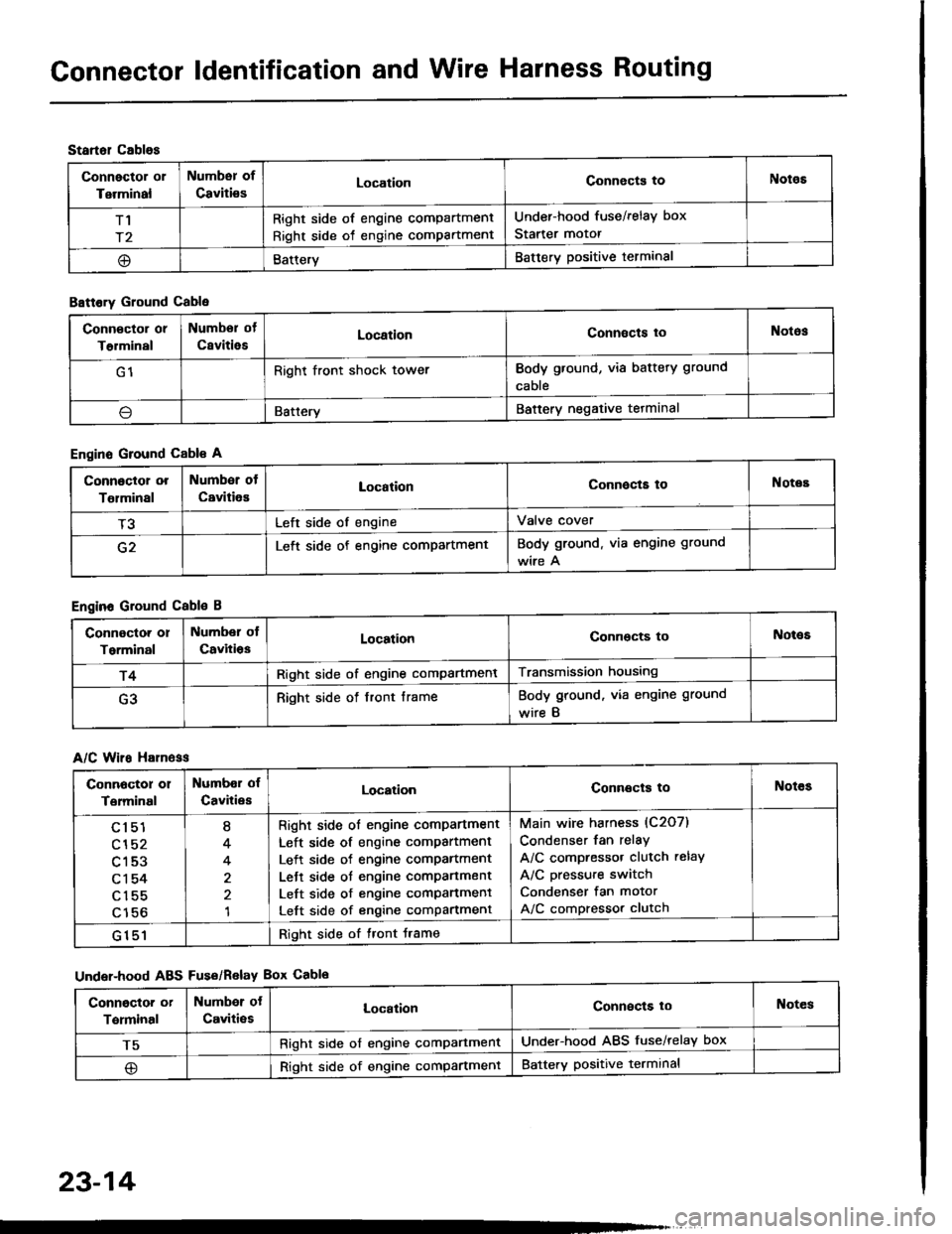
Startol cablos
Connector or
Terminal
Numbsr of
CavitiesLocationConnects toNotos
T1
r2
Right side of engine compartment
Right side of engine compartment
Under-hood fuse/relay box
Starter motor
@BatteryBattery positive terminal
B8ttory Ground Cable
Engine Ground Cable A
Engine Ground Cable B
A/C Wiro H81n6ss
Under-hood ABS Fus€/Relav Box Cablo
Conn€ctor or
T€rminal
Numbor of
CsvitiesLocationConnects toNotos
G1Right front shock towerBody ground, via battery ground
cable
\lBatteryBattery negative tetminal
Connoctor or
Tolminal
Number of
CavitiesLocationConnocta toNotes
T3Left side of engineValve cover
G2Left side of engine compartmentBody ground. via engine ground
wire A
Connoctor or
Torminal
Number ol
CavitiosLocationConnocts toNot€s
r4Right side of engine compartmentTransmission housing
G3Right side of front frameBody ground, via engine ground
wire B
Connoctor 01
Terminal
Numbor of
CavitiesLocationConnects toNotes
cl51
cl52
c153
c1 54
c155
c156
I
4
4
1
Right side ol engine comPartment
Left side of engine compartment
Left side of engine comPartment
Lett side ot engine compartment
Left side of engine comPanment
Left side of engine compartment
Main wire harness (C2O7)
Condenser fan relay
A/C compressor clutch relay
A/C pressure switch
Condenser fan motor
A/C compressor clutch
G151Right side of tront Jrame
Conngctor or
Terminal
Numbor ot
Caviti€sLocalionConnects loNotes
T5Right side of engine comPartmentUnder-hood ABS fuse/relay box
@Right side of engine compartmentBattery positive terminal
23-14
Page 1160 of 1413
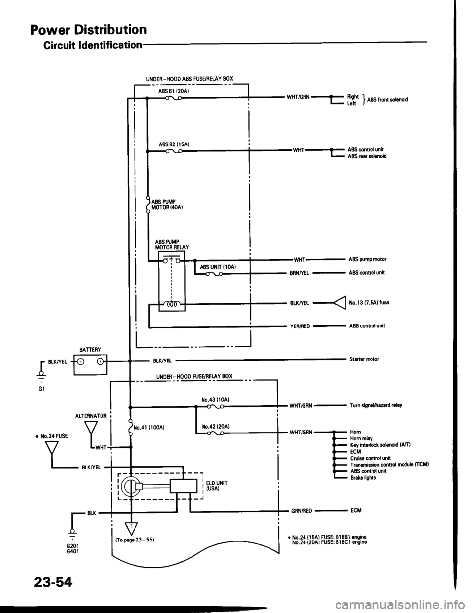
Power Distribution
L"I
.r"-
oiotG401
No.1l (100A)
UNOER-HOOD ABS FUSE/FEIAY 8OX
ABS 81 {2OA)
A86 82 II5AI
Gircuit ldentification
BATTERY
WHT/GRN f Bightr- blt) nas trom sotcooia
ABS oumo motor
8n /YEL - A8S contol unit
Btx/YEL < ib.l3 l7.5Al tu!.
YER/RED - A&S control unit
Stldar motorr BLKffEL
_o_:UNDER - HOOD FUSE/RELAY 8OX
No.43ll0Al
no.42 l20A)
wHT/GRt{ - Turn si0nrl/h.z.rd |thY
WHT/GRN
AL]ERNATOR I
tlomllom mLyKey intodock lohnokl {A/TlECMCruiso control unilTran.mksion control modub (TcMl
ABS contiol unh&6k lighl!
{To psge 23 - 55)
23-54
GRi{/REo - ECM
Page 1172 of 1413

Battery
a Battory tluid (6lectrolyt€l contains sulturic acid. lt may cauaa aevere burns iI it gots on your skin or in youl oyos.
Woar protoctivo clothing and I fac€ shield,- ll aloctrolyt6 gots on youl skin or clothos, rimo it off with wator immediately,- lf eloclrolyto g6ts in your oyos, tlush it out by splashing wat6r in youl eyes for at least 15 minutes; call a physiclan
immediately,
a A battery gives off hydrogon gas, lf ignit6d. tha hydrogsn will orploda and could crack tho baflory cas6 and splattor
acid on you. Koep spa*s. flames, and cigarottos away from the baftery.
a Overcharging will raiso ths tempelature ot th€ electrolyte. This may force electrolyte to splay out of the battery venta.
Follow lhe chargor manutacturer's instluctions and chargo tho battory at a prop61 rate.
NOTE: The original radio has a coded theft protection circuit. lt service to the car requires any of the lollowing, be sure
to get the customer's code number before- disconnecting the battery.- removing No. 32 (7.5 Al fuse from the under-hood fuse/relay box- removing the radio,
After service, reconnect power to the radio and turn it on. When the word "CODE" is displayed, enter the customer's
s-digir code to restore radio operation,
Use either a JCI or Bear ARBST tester, and follow the manufacturer's procedures. It you don'r have one of these com-puterized testers, follow this conventional test procedure:
To get accurate results, the temperature ot the electrolyte must be between TOoF l21ool and IOOoF {38oCl.
lf the case is cracked or the posts are loose,
replace the battery.
lf the indicator shows low electrolvte, add
distilled water it oossible.
Test Load Cspacity (# 1)
. Apply 3OO amp losd fo. 15 seconds to remove
surJace charge.. Allow 15 seconds recovery period.. Apply test load (see Test Load Chartl.. Record voltage at the end of 15 seconds.
Voltage stays above 9.6
volts: The batterv is OK.
23-66
Page 1173 of 1413
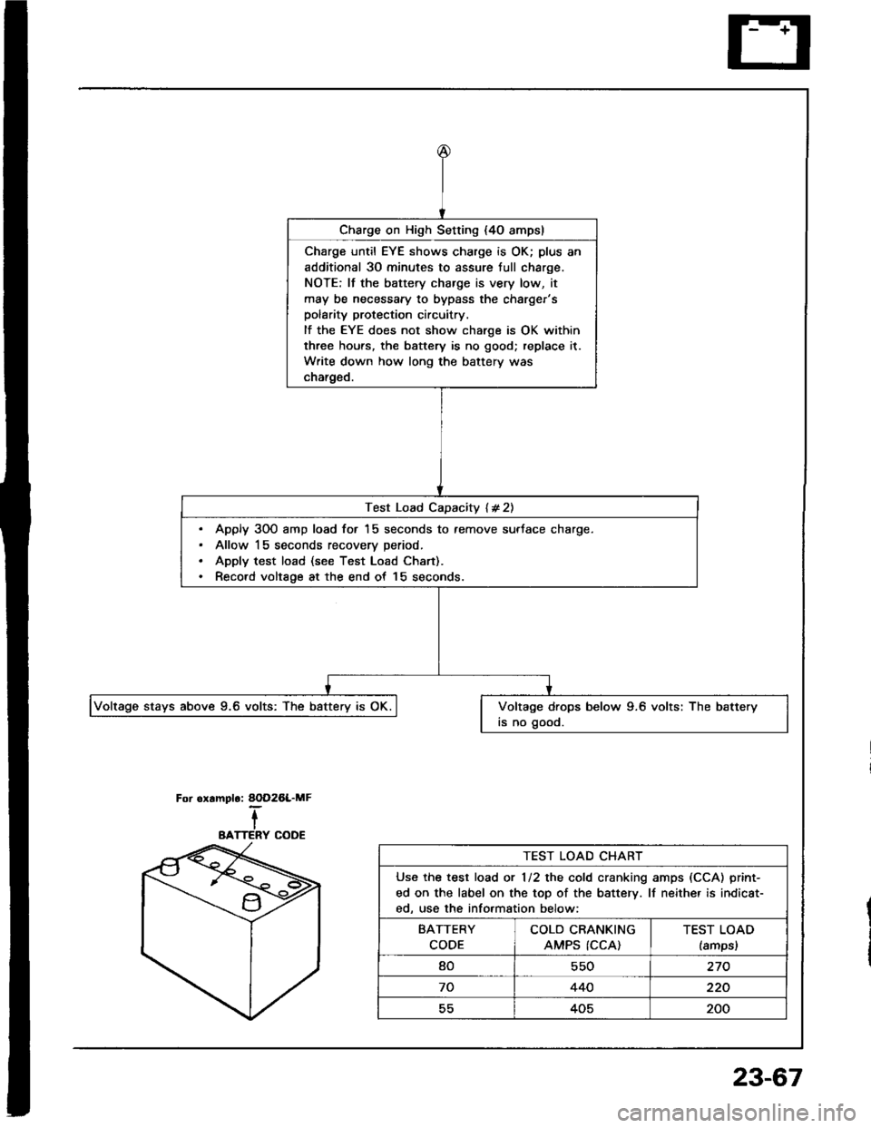
Charge on High Setting {4O ampsl
Charge until EYE shows charge is OK; plus an
additional 30 minutes to assure tull charge.
NOTE: lf the battery charge is very low, it
may be necessary to bypass the charger'spolarity protection circuitry.
lf the EYE does not show charge is OK within
three hours, the battery is no good; replace it.
Write down how long the battery was
charged.
Test Load Capacity l#21
Apply 300 amp load for 15 seconds to remove surface charge.
Allow 15 seconds recoverv Deriod.
Apply test load (see Test Load Chan).
Record voltaoe at the end of 15 seconds.
Voltage stays abov€ 9.6 volts: The Uattery is Of. IVoltage drops below 9.6 volts: The battery
is no good.
AOD26L.MF.-IIERY COOE
For oramplo:
BATTERY COOE
TEST LOAD CHART
Use the test load ot 112 the cold cranking amps (CCA) print-
ed on the label on the top of the battery. lf neithe. is indicat-
ed, us€ the information below:
BATTERY
CODE
COLD CRANKING
AMPS (CCA)TEST LOAD
lamps,
80550270
70440220
55405200
23-67