1994 HONDA INTEGRA alternator wire
[x] Cancel search: alternator wirePage 33 of 1413

ll
il
Standards and Service Limits
ElectricalSection 23
*1: Do not adiust the gap, replace spark plug it it is out of spec.*2r When using a new belt, adjust d€tl€ction or tension to new valu€s. Run tho engine lor 5 minutes thon turn it off.Readiust de{lection or tension to usod belt values.
MEASUREMENTSTANDARD {NEWI
lgnilion coilRat€d voltago VPrimary winding resistance at 58'F (20'C) OSecondary winding resistance 6t 68'F (20"C) kO0.6 - 0.812.4 - 19.2
lgnition wireResistance ar 68"F (20'C) k025 max.
Spark plugTvpeGap B18Bl engineB18Cl engine
STANDARD INEW}SEN$CE UM]T
See Section 231.0 - 1.1 {0.039 - 0.043}1.3 {0.051)rl
lgnition timingAt idling" BTDC (Red)- rpmM/T16" r 2. -750 r 50 (Neurra0
16" t 2" -750 r 50 |!]or L?.lposition)Alternator b€lt'2Deflecrion wilh 98 N {10 kgf,22lbllbetween pulleys9.0 - 11.0 (0.35 - 0.43) with us6d b6li6.0 - 8.0 {0.24 - 0.31} with new b6lt
Eelt t€nsion N (kgf, lbf)Measured with belt tension gsuge340 - 490 {35 - 50, 77 - 110) with used bolt690 - 880 {70 - 90, 154 - 198} with now boh
AlternatorOurput l3.5 V at hot ACoil resistance (rotor) at 68"F {20"C} 0Slip ring O.D.Brush lengthErush spring tonsion N (kgt, lbf)
STANDARD INEWISENUCE UMTT
902.914.4 t0.57)r0.5 (0.41)
3.210.33, 0.73)
tnn ro.rrr1.5 (0.06t
StanerOutputMica depthCommulatot runoutCommutator O.D.Brush lengthBrush spring tension (new) N lkgt, lbf)
0.5 - 0.8 (0.02 - 0.03)0 - 0.02 (0 - 0.0008)29.9 - 30.0 (1.177 - 1.r81)15.0 - 15.5 (0.s9 - 0.61)17.7 - 23.5 fi.8 - 2.4,4.0 - 5.3)
0.2 (0.0081
0.05 t0.@2)29.0 (1.142)
10.0 (0.39)
Page 275 of 1413

ldle Control System
Alternator (ALTI FR Signal
This signals the ECM when the Alternator (ALT) as charging.
D9 l+)
Inspection ot ALT FR Sign.l.
Connect the tost harness betweenthe ECM and connectors. Discon-nect "D" connector from themain wire harnoss only, not theECM lsee page 11-37).
Turn the ignition switch ON.
Measure voltage between D9 (+ )terminal and A26 {-}terminal.
Sub{inno s known-good ECMand redrack. It pro.ctibod volt gola now availablg, ropllco tha orlg-inal ECM.
ls there approx. 5 V?
Turn the ignition switch OFF.
Reconnect "D" connector to themain wire harness,
Start tho engino. Hold the engine
!L3,099 rpm with no load (A/T in
LN] or El position, M/T in neutral)until the radiator tan comes on,rhen let it idle.
Measuro voltage between Dg (fl
terminal and 426 (- I terminal.
Does the voltage decreasewhen headlights and .eardelogger are turned on?Turn ths ignition switch OFF.
ALT FR rignal is OK.
o oo oo o ooooo
ooooooooooo
Voh.go?
ooooooooooo
ooooooooooo
1 1-86
(To page 1 1-87)
=-
Page 1109 of 1413
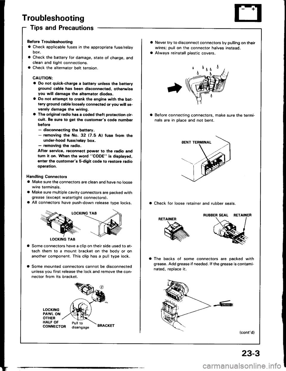
Troubleshooting
Tips and Precautions
Before Troubloshooting
a Check applicable fuses in the appropriate fuse/relay
DOX.
a Check the battery for damage, state of charge, and
clean and tight connections.a Check the alternator belt tension.
CAUTION:
a Do not quick-charg€ a battery unless the batteryground cabla has be€n disconnoctsd. oth€rwisoyou will damage the alternator diodss.a Do not att6mpt to crank the engine with the bat-tery ground cable loosely connectsd or you will se-vorsly damag€ tho widng.
a The original radio has a codod thatt plotection ci.-cuit. Be sul€ to got tho customor's code numbet
before- disconnecting th€ battery.- lomoving tho No. 32 (7.5 Al tuso f.om the
under-hood tuse/lelay box.- removing tho radio.
Aflor s€lvic€. reconn€ct powet to tho radio and
turn it on. Whon the word "CODE" is displayed,
€nt€l the customer'E s-digit codo to .astore ladio
operation.
Handling Connectors
a Make sure the connectors are clean and have no loose
wire terminals.
a Make sure multiple cavity connectots are packed withgrease (except watertight connectors).a All connectors have push-down release type locks.
LOCKII{G TAA
LOCKING TAB
a Some connectors have a clio on their side used to at-
tach them to a mount bracket on the body or on
another component. This clip has a pull type lock.
a Some mounted connectors cannot be disconnected
unless you first release the lock and remove the con-
nector from its bracket.
LOCKINGPAWL ONOTHERHALF OFPull toorsengageCONNECTORBRACKET
23-3
a Never try to disconnect connectors by pulling on thei.
wires; pull on the connector halves instead.
a Always reinstall plastic covers.
Belore connecting connectors, make sure the lermi-
nals are in Dlace and not bent.
a Check tor loose retainer and rubber seals.
RETAINER
a The backs of some connectors are oacked with
grease. Add grease if needed. It the grease is contami-
nated, reDlace it.
(cont'd)
Page 1122 of 1413
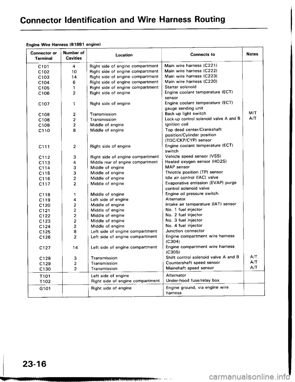
Gonnector ldentification and Wire Harness Routing
Engine Wire Harness {B1881engine)
Connector 01
Terminal
Number of
CavitiesLocationConnects ioNotes
c10'l
c102
c103
c104
c 105
c106
c107
c108
c108
c109
c110
c111
c113
c114
c115
Lt to
c117
c118
c119
c't 20
c121
c122
c123
cl24
c125
c't26
c127
c128
c129
c130
10
14
6
1
1
2
2
8
2
3
t
1
2
2)
2
8
14
2
2
Right side of engine compartment
Right side of engine compartment
Right side of engine compartment
Right side ol engine compartment
Right side of engine compartment
Right side of engine
Right side ol engine
Transmission
Transmission
Middle of engine
lvliddle of engine
Right side ot engine
Right side of engine compartment
ldiddle rear of engine compartment
Middle of engine
Middle ol engine
Middle of engine
Middle of engine
Middle ot engine
Left side of engine
lvliddle of engine
Middle of engine
Middle of engine
Middle ot engine
Middle ol engine
Left side of engine compartment
Left side of engine compartment
Left side of engine compartment
Transmission
Transmission
Transmission
Main wire harness (C221)
Main wire harness {C222}
Main wire harness (C223)
Main wire harness {C220)
Starter solenoid
Engine coolant temperature {ECT)
sensor
Engine coolant temperature (ECT)
gauge sending unit
Back'up light switch
Lock-up control solenoid valve A and B
lgnition coil
Top dead center/Crankshaft
position/Cylinder position
(TDC/CKP/CYP) sensor
Engine coolant temperature (ECT)
switch
Vehicle speed sensor (VSS)
Heated oxygen sensor (HO2S)
MAP sensor
Throttle position (TP) sensor
ldle air control (lAC) valve
Evaporative emission (EVAPI purge
control solenoid valve
Engine oil pressure switch
Alternator
Intake air temperature {lAT} sensor
No. 'l fuel injector
No. 2 tuel injector
No. 3 fuel injector
No. 4 fuel injector
Junction connector
Engine compartment wire harness
(c304)
Engine compartmenl wire harness
(c305)
Shift control solenoid valve A and B
Countershait speed sensor
Mainshaft speed sensor
M/T
NT
NT
NT
T 101
r102
Lelt side oI engine
Right side of engine compartment
Alternator
Under-hood tuse/relay box
G 101Right side of engineEngine ground, via engine wire
harness
23-16
Page 1124 of 1413
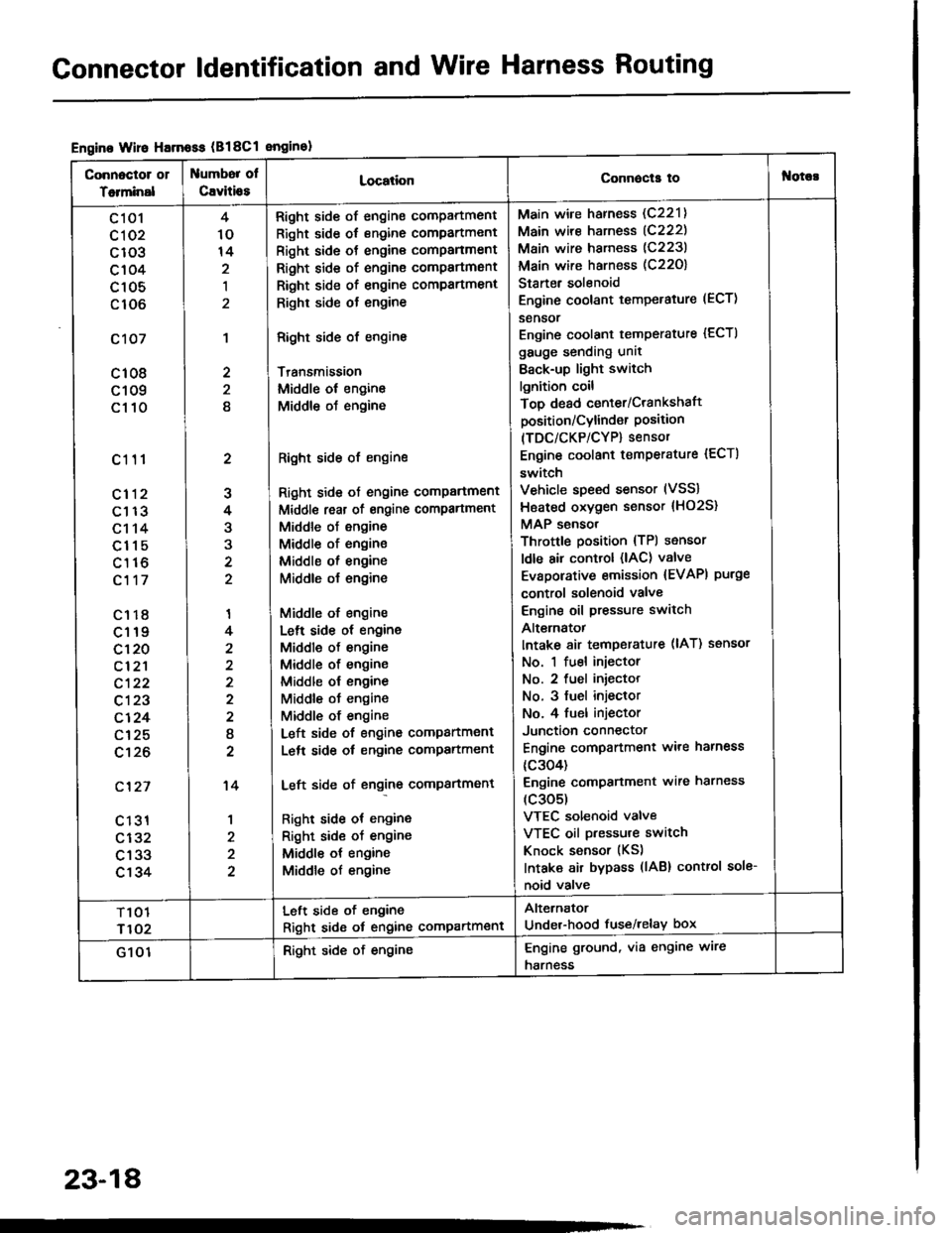
Gonnector ldentification and Wire Harness Routing
Engine Wire Harnoss (B18Cl enginol
Connoctor 01
Totminal
umbor ol
Cavitio8LocationConnecla tof{orc!
c 101
cl 02
c103
c104
c105
c106
c107
c108
c109
c110
c111
cl12
c113
c114
c115
c116
c117
c1r8
c119
c120
cl2'l
c122
c123
c124
c125
c't26
c'127
c 131
c132
c133
c134
2
J
4
3
'I
4
2
I
2
't4
1
4
10
14
,l
2
2
8
Right side of engine compartment
Right side of engine compartment
Right side ot engine comPanment
Right side of engine compartmsnt
Right side of engine compartment
Righr side ot engine
Right side of engine
Transmission
Middle ol engine
Middle oJ engine
Right side of engine
Right side ot engine comPartment
Middl€ reat of engine compartment
Middle of engine
Middle of engine
Middle ol engine
Middle o{ engine
Middle of engine
Lelt side ot engine
Middle of engine
Middle of engine
Middle ol engine
Middle ot engine
Middle of engine
Left side of engine companment
Lelt side ot engine compartment
Left side of engine compartment
Right side ot engine
Right sid€ of engine
Middle ot engine
Middle of engine
Main wire harness (C221)
Main wire harness (C222)
Main wire harness (C223)
Main wire harness (C22O)
Starter solenoid
Engine coolant temperature (ECT)
sensor
Engine coolant temperature {ECTI
gauge sending unit
Back-up light switch
lgnition coil
Top dead center/Crankshaft
position/Cylind€r Position(TDC/CKP/CYP) sensor
Engine coolant temperature {ECT)
switch
Vehicle speed sensor (VSS)
Hsated oxygen sensor {HO2S}
MAP sensor
Throttle position {TPl sensor
ldle air control (lAC) valve
Evaporative emission {EVAPI purge
control solenoid valve
Engine oil pressure switch
Alt€rnatot
Intake 8ir temperature (lAT) ssnsor
No. 1 fuel injector
No. 2 fuel iniector
No. 3 fuel injeclor
No. 4 fuel injector
Junction connector
Engine compartment ware harness
{c304)
Engine comPanment wire harness
(c305)
VTEC solenoid valve
VTEC oil pressure switch
Knock sensor (KS)
Intaka air bypass (lAB) control sole-
noid valve
T101
r102
Left side of engine
Right sid6 ot engine compartment
Alternator
Under-hood fuse/relay box
G 101Right side of engineEngine ground, via engine wire
harness
23-18
Page 1207 of 1413
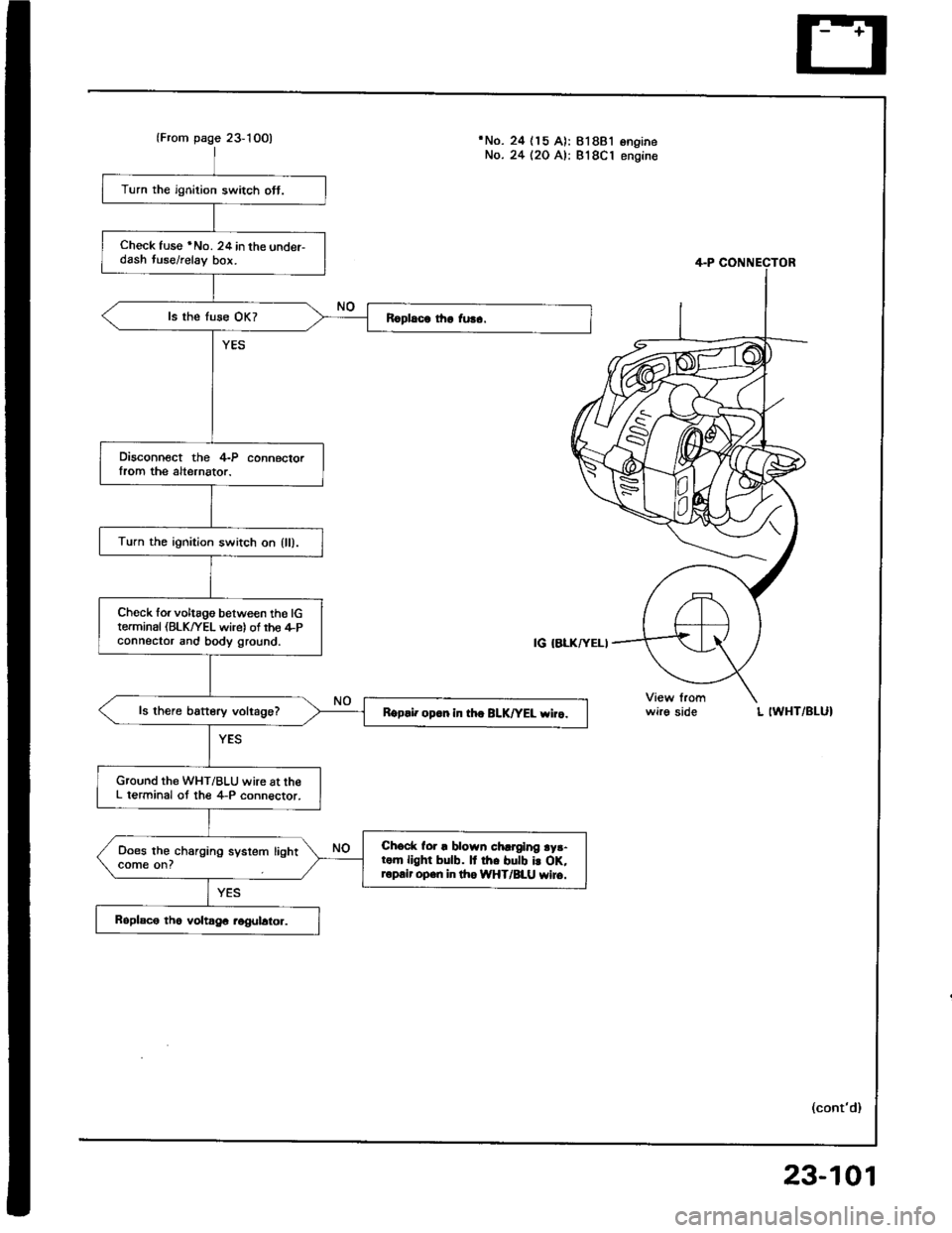
lFrom page 23-10O)'No. 24 (15 A): 818B'lNo. 24 (20 A): 818C1ongrneengine
Turn the ignition switch ott.
Check fuse *No. 24 in the under-dash tuse/relay bor.
Disconnect the 4-P connectorIrom the alternator.
Turn the ignition switch on {ll).
Ch6ck forvoltago between tho lGterminal (BLK/YEL wire) of rho il-Pconnector and body ground.
ls there battery voltage?Rgp.i. op.n in th. BLK|'EL wiro.
Ground the WHT/BLU wire at theL terminal ot the 4-P connector.
Chock for ! blown chrrging ry3-rom llghr bulb. It rh. butb i! oK,ropair open in lho IiYHT/BLU wiro.
Does the charging system lightcome on?
wirg sideL IWHT/BLUI
(cont'd)
23-101
Page 1208 of 1413
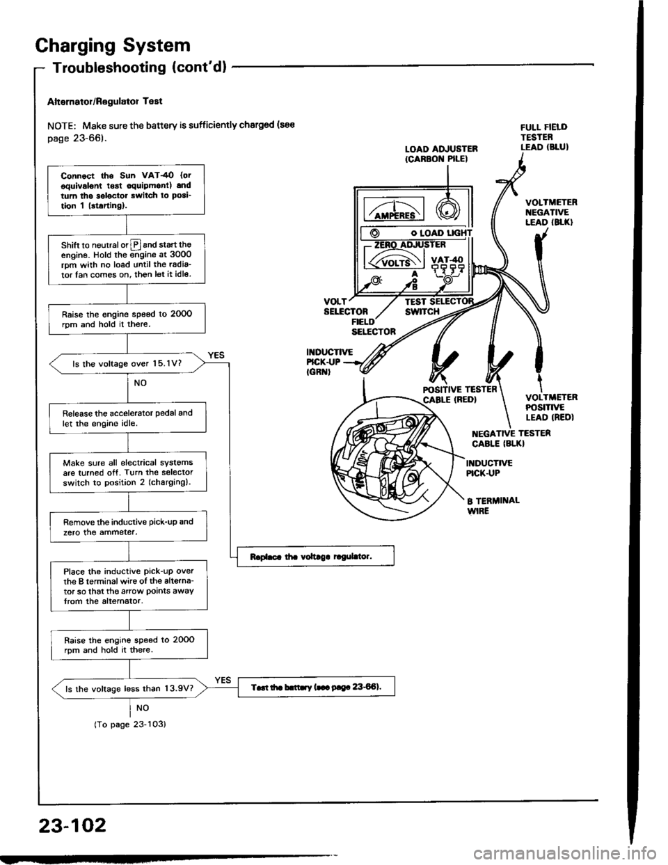
Charging System
Altornator/Regulator Test
NOTE; Mske sure the battery is sufficiently chargod (sa€
page 23-66).
NO
tropagezJ-ruJ,
O IOAD
VOLTTESTSELECTONswlTcH
II{DUCTIVE
FULL FIELDTESTEBLEAD (BLUILOAD ADJUSTERICARBON PILE)
FICK.I.|PIGR '
VOLTMETERt{EGATIVELEAD (8LK}
VOLTMETERPOStTtVELEAD IREDI
EGATIVE TESTER
CABLE (BLKI
INDUCTIVEPICK.UP
B TERMI]TALWIRE
23-102
Connoct tho Sun VAT4O {otooulvslont lgrt equipmonl) andtum tho s6l6ctor rwitch ro posi_
tion I |rtarting).
shift to neurralorlPland start theengino. Hold the ;;gine at 3oO0rpm wiih no load until the radia_
tor lan com€s on. then let it idle.
Raise the engine speed to 2OOOrom and hold il there.
ls lhe voltage over 15.1V?
Release the accelerator pedal andlet the engino idle.
Make sure all electrical systemsare turned otf. Turn the selectorswilch to position 2 (charging).
Remove the inductive pick-up and
zero the ammeter.
Place the inductive pick-uP overthe B terminalwire oI the altgrna-tor so that the arow Doints awaytrom the alternator.
Raise the engins speed lo 20OOrpm and hold it there.
T..t itr b.ttry (.- 9|e. 8€Al.ls the voltage less than 13.9V?
Page 1209 of 1413
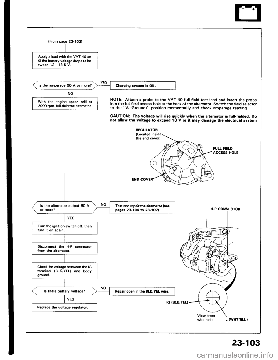
(From page 23-1021
Apply a load wirh the VA'-4O un-til the battery voltage drops to be-tween 12- 13.5 V.
ls the amperage 60 A or more?
With the engine spe6d still at2OOO rpm, full-tield the altemalor.
Toat rnd rooalr d|e dtomEtor {soopsg.. 23-104 to 23-tO7).
Turn the ignition switch off; thenturn at on again.
Disconnocl lhe 4-P connectorIrom the altornator.
Check lor voltage between the lGterminal (BLK/YEL) and bodyground.
ls there battery vokage?Rop.ii open in tho BLK/YEL wiro.
NOTE; Attach a probe to the VAT-4O full field test lead and insert the orobeinto the full tield sccess hole at the back of the alternator. Switch the field selectorto the "A (Ground)" position momentarily and check amperage reading.
CAUTION: The voltago will ris6 quickly whon the slternator is full-fiolded. Donot allow th€ voltago to oxc66d 18 V 01 it may damage the elect.ical system
REGULATOR
{Locatodthe end cover)
FULL FIELDACCESS HOLE
L IWHT/BLUI
4-P CONNECTOR
IG IBLKATELI
wire side
23-103