Page 45 of 1413
Engine
Engine Removal/lnstallation ...''........ 5-1
Cylinder Head/Valve Train ..'............ 6-1
Engine Block ..........7-1
Engine Lubrication ......... 8-1
Intake Manifold/Exhaust System ...... 9-1
Cooling ....... 1O-1
Page 81 of 1413
52 N.m (5.3 kgt'm, 38 lbf'ft)
19. Remove the side engine mount.
10 x 1.25 mm
20. Remove the cylinder head cover.
WASHERS
SIDE ENGINEMOUNT
12 x 1.25 mm74 N.m {7.5 kgf.m,5{ rbtftl
CYLINDEB HEAD
Remove the timing belt (see page 6-10).
Remove the camshaft pulleys and back cover.
23. Remove the exhaust manifold.
SELF.LOOKING NUT8 x 1.25 mm
BACK COVER
BRACKET
(cont'd)
6-19
Page 91 of 1413

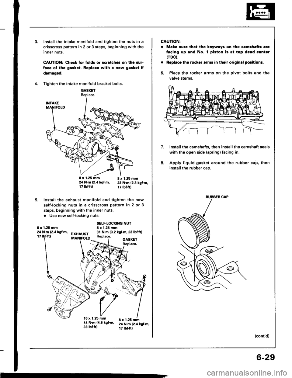
Install the intake manifold and tighten the nuls in a
c.isscross pattern in 2 or 3 steps, beginning with the
inner nuts.
CAUTION: Check to. fold3 or 3cratchc! on ihc aur-
taco ol tho ga3kot. Roplscs with a nlw gaeket if
damagod.
Tighten the intake manifold bracket bolts.
GASXETReplace.
E x 1.25 mm 8 x 1,25 mm2ir N.m l2.it kg{.m, 23 N.m 12.3 kgf.m.17 tbf.ftl 17 tbl.frt
Install the exhaust manifold and tighten the new
self-locking nuts in a crisscross pattern in 2 or 3
steps, beginning with the inner nuts.
. Use new self-lockiflg nuts.
4.
5.
8 x 1.25 mm24 N.m (2,a kgf.m,
SELF.LOCKING NUT8 x 1.25 mm31 N.m (3.2 kgt m,23lbfftlEXHAUST11Replace.
l0 x 1.25 mma,t N.m 14.5 kgf.m,33 tbt.ft)
GASKEIReplace.
8 x 1.25 mm2il N.m 12.4 kg{.m,17 rbtftl
m
CAUTION:
. Mlka 3uro thrt thc k.ywlyr on tho c.mthlttr lrc
facing up .nd No. I pi3ton i3 8t top d.rd clnt.r(TDCt.
. Rcphct th! rocksr armr in thsir o.iginal potltlom.
6, Place the rocker arms on the oivot bolts and ths
valve stems.
lnstallths camshafts, then installth€ camshaft sosls
with ths open side (spring) facing in.
Apply liquid gasket around the rubber cap, then
installthe rubber cao.
7.
8.
(cont'd)
6-29
Page 119 of 1413
Cylinder Head
Removal (cont'dl
Remove the heat shield from the P/S bracket (see
page 5-18).
Remove the air conditioning (Ay'Cl compressor belt(see page 6-49).
Remove the alternator belt {s€e page 6-49).
Remove the cruise control actuato..
16.
17.
'18.
'19.
ACTUATOR
20. Remove the side engine mount.
10 x 1.25 mm
SIDE ENGINE
12 x 1.25 mrn7a N.m 17.5 kgl.m,5a rbtftl
8 x 1.25 mmN.m 12.4 kgf.m, 17 lbtftl
21. Remove the cylinder head cover.
22. Remove the timing belt (see page 6-49).
23. Remove the camshaft pulleys and back cover.
24. Remove the exhaust manifold.
SELF.LOCKING NUT8 x 1 .25 mm31 N.m {3.2 kgt m, 23 lbf.ftlReplace.
6-58
'ilffi{
Page 120 of 1413
25. Remove the intake manifold.
26. Loosen the adjusting screws.
INTAKENo.4 No.3 No.2No. 1
No. 4No.3 No. 2EXHAUSTNo. 1
GASKET
21.Remove the camshaft holder plates, camshaft hold-
ers, and camshafts.
CAMSHAFT
28. Remove the cylinder head bolts, then remove the
cylinder head.
CAUTION: To prsvent warpage, unscrew th€ bolts
in sequence l/3 turn at a time; repeat until all bolts
aro loosoned.
CYLINDER HEAD BOLT LOOSENING SEOUENCE
6-59
Page 137 of 1413
Cylinder Head
8 r 1.25 mm2a N..n 12.4lgtm,r 7 tbf.ftl
Installation {cont'd)
4. Install the exhaust manifold and tighten the new
selJ-locking nuts in a crisscross pattern in two or
three steps, beginning with the inner nuts.
. Use new self-locking nuts.
SELF.LOCKING NUT8 x 1.25 mm31 N.m 13.2 kgf'm, 23 lbtltlReplace.
EXHAUST
a.l N.m 14.5 kgt m,33 tbr.trl
GASKETReplsco.
8 x 1.25 mm24 N.m (2.4 kgt m,rt tbfft)
&,x
6-76
5. Install the camshafts, camshaft oil seals and rubber
cap.
NOTE:
. Install the camshafts with keyway facing up.
o Installthe oil sealwith the spring side facing in.
. The oil seal housing surface should be dry,
. Set the O-ring and dowel pin in the oil passage
of th€ No. 3 camshaft holder
Kgyway is lacing up.
Apply liquid gasket around the rubber cap, then
install the rubber cap.
O-RING {ReDlace.)
Page 179 of 1413
lntake Manifold/Exhaust System
Intake Manifold
Replacement ............................... 9-2
Exhaust Manifold
Replacement ............................... 9-4
Exhaust Pipe and Muffler
Replacement ............................... 9-5
Page 182 of 1413
Exhaust Manifold
Replacement
NOTE: Use new gaskets and seltiocking nuts when teassembling.
GASKETReplace.
€XHAUST MAt{IFOLD
I r 1.25 mm24 N.ln (2.4 kgf.m, l7 lbt.ft)
Z \
i...1%\
/ \-i
8x2417
tr l'A
| 1tr.
/\
t\
I
I1.25 mmN.m {2.4 kgf.m,tbf.ftl
8 x '1.25 mm3l N.m {3.2 kgf.m. 23 lbf.ltlReplace.
10 x 1.25 mm44 .m {4.5 kgl.rh. 33 lbf.ft}
Ss
R
A\