Page 229 of 1413
It the inspection for a particular code requires the test harness. remove the right door sill molding and kick panel. Pull
the carpet back to expose the ECM, Unbott the ECM cover. Turn the ignition switch off and connect the test harness
Check the system according to the procedure described for the appropriate code(s) listed on the following pages.
KICKPANEL
TESTHARNESSOTLAJ _PT3OlOA
DIGITAL MULTIMETERCommarcially ovribbla orKS-AHM-32-OO3
NOT USED
TERMINAL LOCATIONS(cont'd)
o oooooooooooo
ooooooooooooo
oo o oo ooo
oooooooo
ooooooooooo
ooooooooooo
11-37
Page 244 of 1413
PGM-FI System
Manifold Absolute Pressure (MAP) Sensor
fxai - lfil1 The Malfunction Indicator Lamp (MlL) indicates Diagnostic Trouble Code (DTC) 3: An electrical
-:- -?- problem in the Manifold Absolute Pressure (MAPI Sensor circuit.
The MAP sbnsor converts manitold absolute pressure into electrical signals and inputs the ECM.
OUTPUTVOLTAGE
600 700
(in. Hsl GAUGEREADIIIO{mft Hg)
YEL/RED lBlSBl onginc)YEL^YHT lBlaCl .ngin.l | + I
{+l
SENSOR
1.5
- Tho MIL has boon roportod on.- Wirh tho SCS rhort connoctorconnectod lsoo pags 11-34),codo 3 b indicatsd.
Do the ECM Reset Procedure {soepage 11-35).
Intormittont tailuro, lystom ir Ol(at thls timo {tort drivo may bsnocessary).Chack to? Door connocllon oiloosa wiroa 6t C223 {locltod atright shock tow6rl, C'l 14 (MAP
sonaorl and ECM.
ls the MIL on and does it indi-cate code 3?
Turn the ignition switch OFF.
Disconnect the 3P connector tromthe MAP sensor,
Turn the ignition switch ON.
{To page 11-53)
11-52
Page 256 of 1413
PGM-FI System
lgnition Output Signal
i16;11 :ffi1 The Malfunction Indicator Lamp (MlLl indic8tes Diagnostic Trouble Code (DTC) 15: A probl€m in'--=-- . -r- t the lgnition Output Signsl circuir.
I
NOTE| ll the onoine won't stan. itmay take 20 seconds ot cranking to5€t th€ COde.
D|STNIBUTOB
wir6 sido
- Th. MIL hsr b..n roport.d od.- Widr ths SCS .hon cohnecto.connoct€d {..o plgo 11-341,codg |5 i! indicatrd.
Do the ECM Reset ftocedure (seepage 'l'l-351.
Intarmltt nt hllur.. ryltam i. OK!t drlr dm. (t |l drlva mly bonaoaaalry).Chack tor Door cmnactiona orloo|. rYlrar !t C223 llocltld !trlghr .hoct tow.rl, Cl10 (lCMl.nd ECM.
ls th€ MIL on and do€s it indicatecode 15 ?
Turn the ignition swirch OFF.
Turn the ignition switch ON.
Measure voltage betwoon BLK/YEL (+) terminal snd bodygrouno.
R.p.ir op.n In BLK/YEL wlr. bo-ftvarn th. 2P conn.cior lnd ioni-tion rwitch.
ls the.e battory voltage ?
(To page 11-67)
11-66
re*,
Page 260 of 1413
![HONDA INTEGRA 1994 4.G Workshop Manual PGM-FI System
Electrical Load Detector (ELDI
tft;-]/ The Maltunction Indicaror Lamp (MlL) indicatss Diagnostic Trouble Code IDTC) 20: A probtem in-Li!- tne Electrical Load Detecror {ELD} circuit.
With HONDA INTEGRA 1994 4.G Workshop Manual PGM-FI System
Electrical Load Detector (ELDI
tft;-]/ The Maltunction Indicaror Lamp (MlL) indicatss Diagnostic Trouble Code IDTC) 20: A probtem in-Li!- tne Electrical Load Detecror {ELD} circuit.
With](/manual-img/13/6067/w960_6067-259.png)
PGM-FI System
Electrical Load Detector (ELDI
tft;-]/ The Maltunction Indicaror Lamp (MlL) indicatss Diagnostic Trouble Code IDTC) 20: A probtem in-Li!- tne Electrical Load Detecror {ELD} circuit.
With lho SCS lhon connectolconnoctod {ree pago 11-34}, cod.20 is indicatod.
Do the ECM B6set Procedurs {seepage 1 'l-35).
Start engine and keep engin€speed at idle.Turn on headlights.
lntennlna tlllure, lyrtom lt Ol(!t irl. dm. (lgtt driv. mly [email protected] for Door connactlona oaloota wiro. rt C218 IELD, lndEctrt.
Ooes the MIL indicato code 20?
Romove the undgr-hood fusg/relay box and remove the tus6/relav box lowet cover.
Turn lhe ignition switch ON.
Measure voltage betw€on BLK/YEL (+l terminal and BLK (-)terminal.
Msasuro voltag€ b€tweon BLK/Y€L {+) terminal snd bodvground.ls there bartory voltagel
Rcpir oo.n in BLK wir.batwaan lha 3P connrc-tor lnd G2Ol {loc.t.dtroit ot angh|. comprn-m.r dghl .ld.l,
B.p.lr op.n in BLKrYEL wlrr b.-tw..n o.24ACG (ALn flcl115A: Bl88l .ngln!, 20 A:818C1cnginol fu!. In thr und.r{..htu.o/r.lly bor lnd tho 3P con-rcclo?.
View tromwire side
BLK (-)
(To page 11-7'l)
GRn/iED I - |
BLK/YEL I + I
11-70
Page 916 of 1413
15. After the clearances have been adjusled properly.
reinstall the weatherstrip.
16. Check that the glass contacts the weatherstrip
evenly.
NOTE: Measuring points are described on page
20-42.
Conter Pillar soction:
WEATHERSTRIP
17.Check for water leaks.
NOTE; Do not use high pressure water.
18. Route the door harness and connectors, and fasten
them to the door (see pages 20-22, 331.
19. Disconnect the oowef window switch from the doo.
harness, then install the power window switch on
the door panel (see page 20-41).
2O. Attach the plastic cover, then install the door panel
(see pages 2O-2O, 321.
2047
Page 1038 of 1413

Heater
lflustrated Index ............. .........21-2
Heater Door Positions .........,..,. 21-3
Circuit Diagram ....................... 21-6
Troubleshooting
Symptom Chart ............. ......21-8
Flowcharts
Blower Motor Speed ............................... 21 -9
Bfower Motor .........,..,,,,,.. 21-11
Mode Control Moto. ............ ................... 21 -14
Recircufation Control Motor ......,...,.,,,.,.... 21 -17
Heater Control Panel Input/
Output Signals ..............21-19
Blower Unit
Repfacoment ....................... 21-20
Overhaul .......21-21
+Heater Unit
Repfacement ....................... 21-22
Overhaul .......21-24
Def roster Door Adjustment ...,............. ......,, 21 -25
Heatel Control Panel
Repfacoment ....................... 21-25
Overhaul .......21-26
Heater Valve Cable
Adjustment ...21-27
Air Mix Control Cable
Adjustment ... 21-27
Mode Control Motol
Test .............. ..................... 21-2e
Repfacement ..,..............,,,,.. 21-28
Recirculation Control Motor
Test .............. ..................... 21-29
Repfacement ....................... 21-29
Relay
Test .............. ..................... 21-30
Heater Fan Switch
Test .............. ..................... 21-30
Mode Control Switch
Test .............. ..................... 21-31
Recilculation Control Switch
Test .............. ..................... 21 -31
*: Read SRS precautions before working in this area.
Page 1062 of 1413

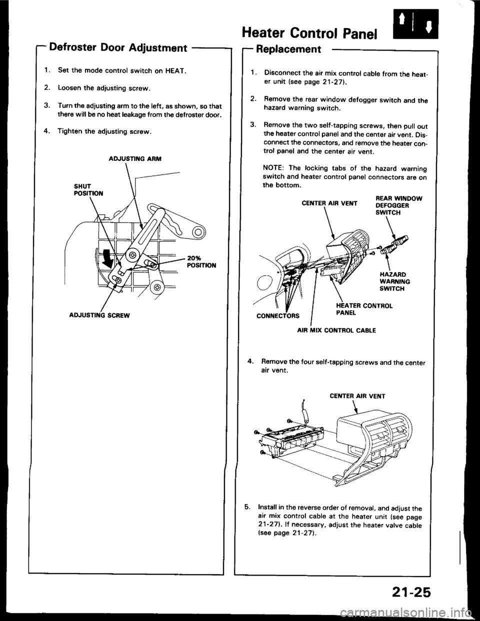
Defroster Door Adjustment
Set the mode control switch on HEAT.
Loosen the adiusting screw.
Turn the adjusting arm to the left, as shown, so that
there will be no heat leakage from the defroster door,
Tighten the sdjusting screw.4.
CE]TTER AIR VEI{T
4. Remove the four self-tapping screws and the centerair v€nt.
Install in the reverse order of removal. and adjust theair mix control cable at the heater unit lsee page21-27). lf necessary, adjust the heater valve cablelsee page 21-27).
REAR WITIDOWDEFOGGERswtTcH
Heater Control Panel
Replacement
Disconned the air mix control cable from the heat-er unit lsee page 21-271.
Remove the rear window defogger switch and thehazard warning switch.
Remove the two self-tapping screws, then pull outthe heater control panel and the center air vent. Dis-connect the connectots, and remove the heater con-trol panel and the center air vent.
NOTE: The locking tabs of the hazard warningswitch and heater control panel connectors are onthe bottom.
AD.'USTII{G ARM
ADJUSTI G SCREW
AIR MIX CONTROL CABLE
CENTEB AIR VE T
21-25
Page 1092 of 1413

A/G System Service
Performance Test
The performance test will help determine if the air con-
ditioner system is operating within specitications.
Only use service equipment that is U.L.-listed and is cer-
tified to meet the requirements of SAE J2210 to remove
HFC-134a {R-134a) from the air conditioner system.
CAUTION: Exposure to air conditioner relrig€rant and
lubricant vapor ot mist can irritate eyes, nose and
throat. Avoid breathing the air conditioner rstrigerant
and lubricant vapor or mi3t.
It accidental system discharge occurs, ventilate work
area before resuming service.
R-134a service equipment or vehicle air conditioner sys-
tems should not be pressure tested or leak tested with
comPressed atr.
!@ some mixtures ot air and R'1344 hrv6
been shown to be combustibls at elovatod prsssurel
and can result in firg or explosion causing iniury 01
property damage. Ngvor usg compregsed ail to prossuro
t€st R-134a ssrvice equipment or vohicl€ air conditioner
syst€ms.
Additional health and safety information may be
obtained from the refrigerant and lubricant manufactur-
ers.
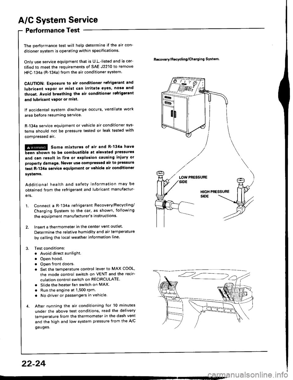
1. Connect a R-134a refrigerant Recovery/Recycling/
Charging System to the car, as shown, iollowing
the equipment manufacturer's instructions.
2. Insert a thermometer in the center vent outlet.
Determine the relative humidity and air temperature
by calling the local weather information line,
3. Test conditions:
. Avoid direct sunlight.
. Open hood.
. Open front doors
. Set the temperature control lever to MAX COOL,
the mode control switch on VENT and the recir-
culation control switch on RECIRCULATE.
. Slide the heater fan switch on MAX
. Run the engine at 1,500 rPm
. No driver or passengers in vehicle.
4. After running the air conditioning for 10 minutes
under the above test conditions. read the delivery
temperature from the thermometer in the dash vent
and the high and low system pressure from the A,/C
gauges.
Rocov.rylB.cycling/Ch!lging SFtrm.
PRESSURELOW
22-24