Page 1324 of 1413
Power Mirrors
Switch Test
Remove the driver's door panel (see section 2O).
Check tor continuitv between the terminals in each
switch position according to the table.
Mirror Switch
rermrnal
Position \J
R
OFFG"
UP
-o
o--<>-
DOWN
-o
o--o
LEFTo-
-o
RIGHT
-o
o-
OFFo--o
UP
o--(J_
DOWN
-o
G--o
tEFT
-o
-o
RIGHTG-
P-o
23-214
aaaaaaaa
A-------+J
Page 1325 of 1413

FunctionTest
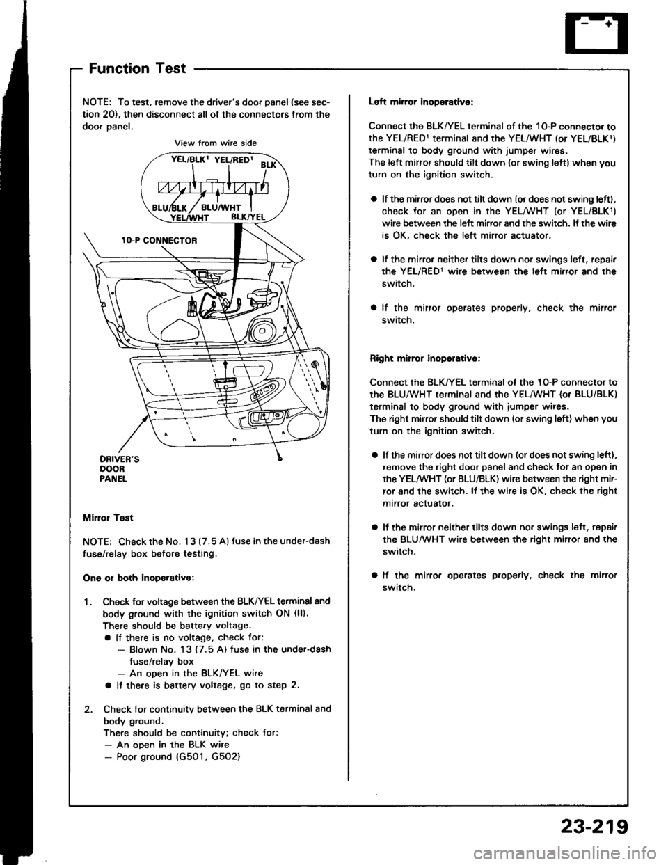
NOTE: To test, remove the driver's door panel (see sec-
tion 20), then disconnect all of the connectors from the
door oanel.
Miror Tost
NOTE; Check the No. 13 (7.5 A) tuse in the under-dash
fuse/relay box before testing.
Ono or both inop€rativa:
1. Check for voltage between the BLKIrEL terminal 8nd
body ground with the ignition switch ON (ll).
There should be battery voltage.
a lf there is no voltage, check tor:- Blown No. 13 {7.5 A) fuse in the under-dash
fuse/relav box- An ooen in the BLK/YEL wire
a It there is battery voltage, go to step 2.
2. Check for continuity between the BLK terminal and
body ground.
There should be continuity; check Jor:- An ooen in the BLK wire- Poor ground (G501, G5O2)
View from wire side
Loft mirror inopsrative:
Connect the BLK/YEL terminal of the 10-P connector to
the YEL/RED1 terminal and the YEL/WHT (or YEL/BLKr)
terminal to body ground with jumper wires.
The left mirror should tilt down (or swing leftl when you
turn on the ignition switch.
a lf the mirror does not tilt down (or does not swing leftl,
check Jor an open in the YEL/WHT (or YEL/BLK1)
wire between the left miffor and the switch. It the wir€
is OK, check the left mirror actuator.
a lf the mirro. neither tilts down nor swings left, repair
the YEL/RED1 wire between the left mirror and the
switch.
a lf the mirror operates properly, check the mirror
swatch.
Right mirror inoporative:
Connect the BLK/YEL terminal of the 1O-P connector to
th€ BLU/WHT terminal and the YEL/WHT {or BLU/BLK)
terminal to body ground with iumper wires.
The right mirror should tilt down (or swing left) when you
turn on the ignition switch.
a lf the mirror does not tilt down (or does not swing left),
remove the right door panel and check for an open in
the YELMHT (or BLU/BLK) wire between the right mir-
ror and the switch. lf the wire is OK. check the right
mtrror actualor.
a ll the mirror neither tilts down nor swings lelt, repair
the BLUMHT wire between the right mirror and the
switch.
a lf the mirror operates properly, check the mirror
swatch.
23-219
Page 1332 of 1413
Power Windows
Master Switch Input Test (Sedan)
NOTE; The control unit is built into the Dower window
maste. switch, and onlv controls driver's door window
ooerations.
1. Remove the driver's door panel and disconnect the
16-P and 1-P connectors from the master switch.
2. Inspect the connector and socket terminals to be
sure they are all making good contact.
a lf the terminals are bent, loose or co.roded, reDair
them as necessary. and techeck the system.a It the terminals look OK, make the following in-
put tests at the connecto..- It a test indicates a problem, tind and correct
the cause, then recheck the system.- lf allthe input tests prove OK, the power win-
dow master switch must be faulty; replace it.
23-226
BEDI'EL I GRN
8LU/YEL I YEL/BLK
View from wire side
View lrom wire side
Page 1334 of 1413

Power
Master
Windows
Switch lnput Test(Hatchback)
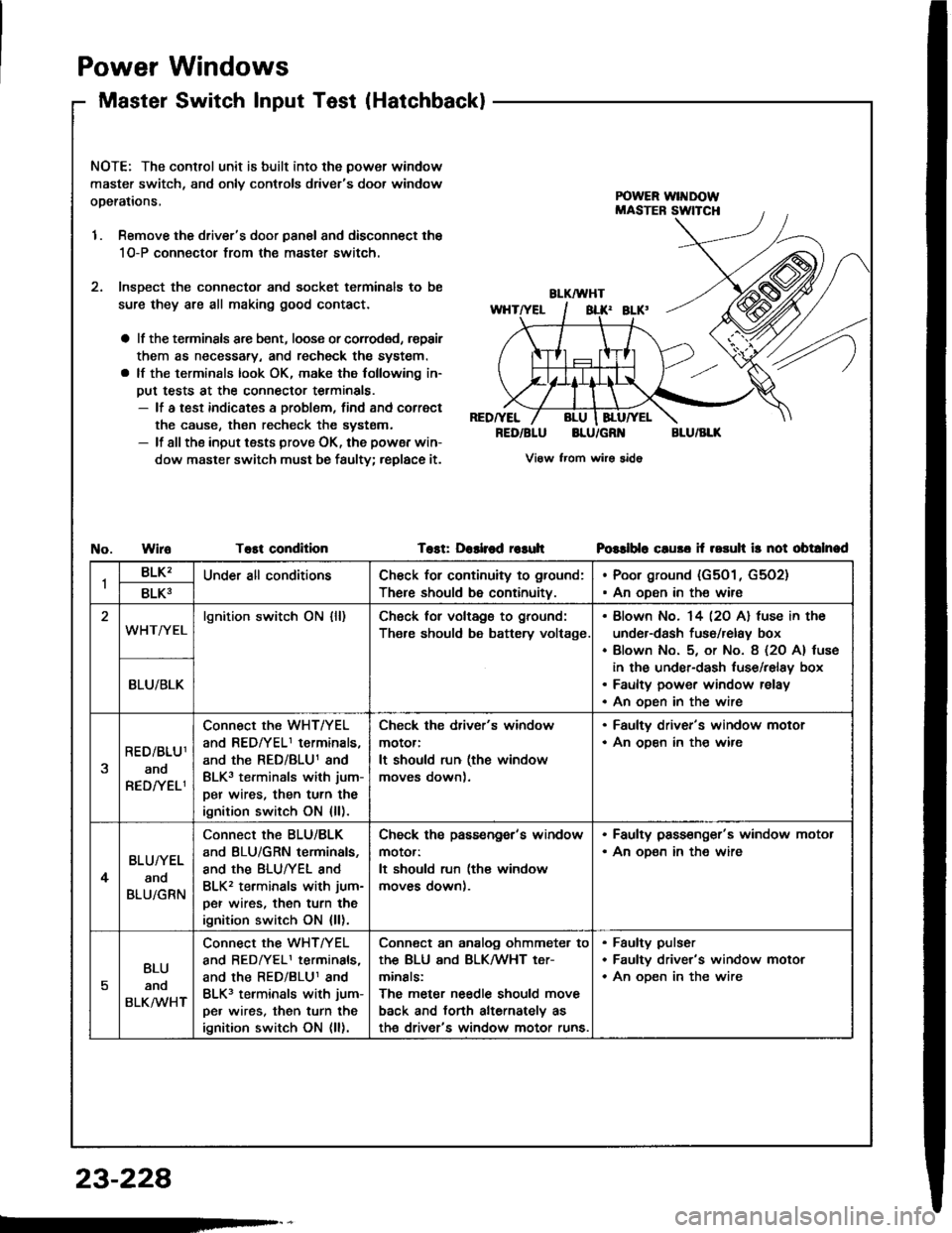
NOTE: The control unit is built into the power window
master switch, and onlv controls driver's door window
operations,
1. Remove the driver's door panal and disconnect the
1O-P connectol from the master switch.
2. lnsDect the connector and socket terminals to be
sure they are all making good contact.
a lf the terminsls arc bent, loose or corroded, rspair
them as necessary, and recheck the system.
a lf the terminals look OK, make the following in-
put tests at the connector terminals.- lf a test indicates a problem, find and correct
the cause, then recheck the systsm.- lf all the input tests prove OK, the powsr win-
dow master switch must be faulty; replace it.
RED/YEL
RED/BLUBLU/GR'{BLU/BLK
View from wirs sido
WiroTost conditionTost: Dashod r€suhPGslblo cluso if rosuh ir not obtalnad
1BLK'Under all conditionsCh€ck for continuity to ground:
There should be continuity.
Poor ground (G501, G5O2)
An oDen in the wire8LK3
WHT/YELlgnition switch ON {ll)Ch6ck for voltags to ground:
Th€re should be battery voltage.
Blown No. 14 l2O Al fuse in the
under-dash fuso/relay box
Blown No. 5, or No. 8 (2O A) tuse
in the under-dash luse/relay box
Faulty power window relay
An oDen in the wire
BLU/BLK
RED/BLU1
ano
RED/YELI
Connect the WHT/YEL
and REDfYELI terminals,
and the RED/BLU1 and
BLK3 terminals with jum-
per wires, then turn the
ignition switch ON {ll).
Check the driver's window
motor:
It should run (the window
moves down).
. Faulty driver's window motor. An ooen in th€ wire
4
BLU/YEL
and
BLU/GRN
Connect the BLU/BLK
and BLU/GRN terminals,
and the BLUTYEL and
BLK2 terminals with jum-
per wires, then turn the
ignition switch ON {ll).
Check ths passengor's window
motor:
It should run (the window
moves down).
. Faulty pass€nger's window motor. An oD€n in the wire
5
BLU
anq
BLKMHT
connect the WHTTYEL
and BEDrYELI terminals,
and the RED/BLU1 and
BLK3 terminals with jum-
pe. wires, then turn the
ignition switch ON (ll).
Conn€ct an analog ohmmeter to
thE BLU ANd BLKMHT t€Tr
minals:
The meter needle should move
back and torth alternately as
th€ driver's window motor runs.
Faulty pulser
Faultv driver's window motor
An oDen in the wire
23-228
Page 1335 of 1413

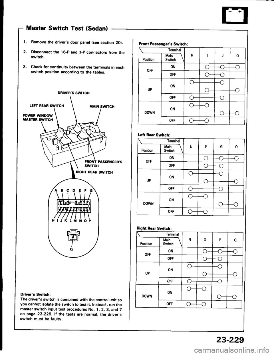
Master Switch Test (Sedan)
1. Remove the driver's door pan6l (sse section 2O).
2. Disconn€ct the 16-P and l-P connectors trom theswitch.
3. Check for continuity b€tw€€n tho terminals in eachswitch position according to the tables.
LEFT REARMAtit swtTcH
POWER wl DOWMASTEB SW]TCH
PASSEI{GER'SswtTcH
RIGHT REAN SW|TCH
Ddv.r't Swh.tr;
Th6 driv€r's switch is combined with the cont.ol unit soyou cannot isolate the switch to t6st it. Instead , run themaater switch input test procedurss No. 1 , 2. 3, and 7on page 23-226. lf the tests are normal, th6 driver,sswitch must be fsulty.
DRIVER'S SWTCH
ABCDE
Front Paslongrr't Swltch:
Terminal
HoI Main \Position I Swirch \
OFFONo-r)--o
OFFG----o
UPON
--o
O-
OFFo---o
DOWNON
o---o
OFFo--_o
Lcft Rear Swhch:
Terminal
EFoj Main IPosition I Switch \
OFFONo-o--o
OFFo---o
UPONo---o
--oo-
ut'fo---o
DOWNONo---o
G---o
OFF-o
Rlght Roar Swhch:
Teminal
N0oI Main If
Position I Switch \
OFFONG_o--o
OFFo---o
UPot'lo---o
--o
OFFo----o
DOWNONo---o
o--o
OFFG---o
23-229
Page 1336 of 1413

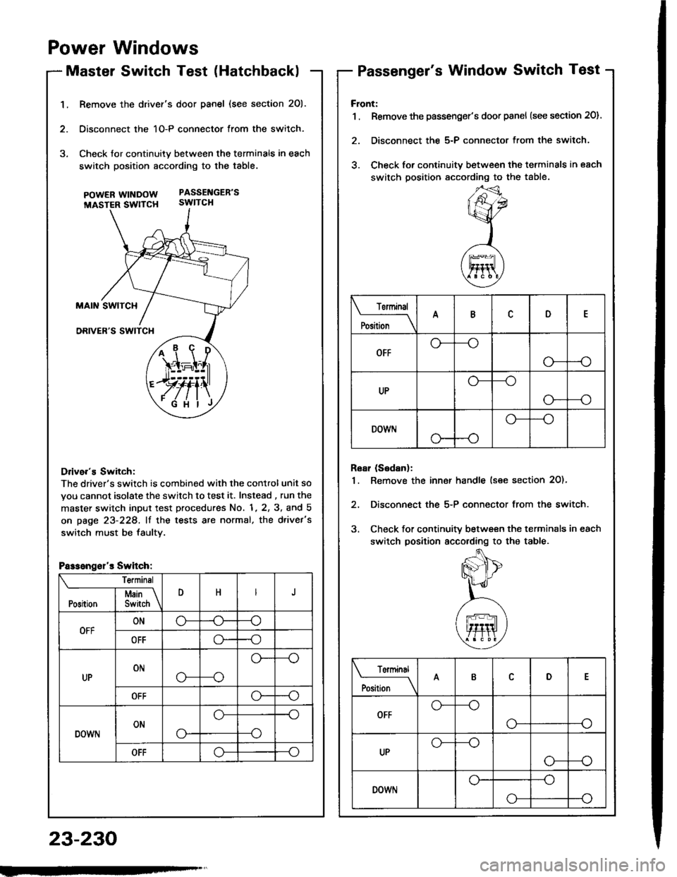
1.Remove the drivef's door panel (see section 201.
Oisconnect the 1O-P connector from the switch.
Check tor continuity between the terminals in each
switch position according to the table.
pOWERWTNDOW PASSENGEB'S
MASTER SWTTCH SWITCH
Drive.'s Switch:
The driver's switch is combined with the control unit so
you cannot isolate the switch to test it. Instead , run the
master switch input test procedures No. 1, 2, 3, and 5
on page 23-228, lf the tests are normal, the d.ivet's
switch must be faultv.
i1\i
\4r-I^l,r
)rvti\
.Fi'ilj
Passengsl'r Switch:
Te.minsl
DHJI Msin \Position I Switch \
OFFONo-(J--o
OFFo--o
UPONo---o
o--
OFFo--o
DOWNONo-
o--o
--o
OFFo--o
Power Windows
Master Switch Test (HatchbacklPassenger's Window Switch Test
23-230
Front:
1 . Remove the passenger's door panel {see section 20).
2. Disconnect the 5-P connector from the switch.
3. Check for continuity between the terminals in each
switch position sccording to the table.
Rear (Sedanl:
1. Remove the inn€r handle (see section 2O)'
2, Disconnect the 5-P connector from the switch.
3. Check for continuity between the terminals in each
switch position according to the table.
Torminal
il;_\
ARD
OFFo-
--o
UPo---o
G_--o
DOWr.lo---o
Terminal
;;__\ID
OFFG_--o
o---o
UPG_--o
o---o
DOWNo---o
o-
Page 1337 of 1413
Master Switch ReplacementPassenger's Window Switch
Hatchback:
1. Remove the driver's door panel (see section 20).
2. Disconnect the 1O-P connector lrom the switch,
3, Remove the three mounting screws and the switch.
Sedan:
1. Remove the driver's door panel (see section 2O).
2. Disconnect the 1 6-P and 1-P connectors from the
switch.
3. Remove the two mounting screws and the switch.
POWER MIRRORswtTcH
scREws
Replacement
Flont:
1 . Remove the passenger's door panel (see section 201.
2. Disconnect the 5-P connector from the switch.
3. Remove the two mounting screws and the switch.
Roar (S6danl:
1. Remove the inner handle (see section 20).
2. Disconnect the 5-P connector from the switch.
3. Remove the two mounting screws and the switch.
w|I{Dow.swtTcH
swtTcl{
INNER HANDLE
23-231
Page 1339 of 1413
Power Door Locks
Component Location Index
1
FRONT PASSENGER'S DOOR LOCK ACTUATORTest. pago 23-239Reolacement. section 20
FRONT PASSENGER'SDOOR LOCK SWITCHfest, page 23-241
FRONT PASSENGER'S DOOR KEYCYLII{DER SWITCHTest, page 23-240
POWER OOOR LOCKCONTROL UNITfnput Tost, page 23-236
RIGHT REAR DOOR LOCK ACTUATOR lsodanlTest,
DOORKEY CYLINDER SWITCHTest. page 23-24O
DBIVER'S
DOOR
LOCK ACTUATORTest, page 23-238Roplacement, seclion 20
LOCK SWITCH'lest, page 23-241
Description
For this model, a new door lock system has been adopted to improve convenience and safety. lf the kev is insened intothe driver's door key cylinder, turned to the unlock position, and pulled out immediately thereafter, oNLy the driver.sdoor will unlock. However, if the key is kept in the unlock position tor one second or more, ALL doors wi
unlock.
23-239
LEFT REAR DOOR LOCK ACTUATOR {Sodan}Test, page 23-239
23-233