Page 1189 of 1413
Check for mica depth. It necessary, undercut micawith a hacksaw blade to achieve proper depth.
ITOT GOOO
MICA DEPTH
Commutator Mica D6pth
Stsndard {Nsw):0.5-0.8 mm (O.O2-0.03 in}Sslvice Limit: 0.2 mm (O.OO8 inl
Check tor continuity between the segments of thecommutator. lf an open circuit exists between anvsegments, replace the armatute.
M
ARMATURE TESTER
ARMATUFE
Place the armatute on an armature tester. Hold ahacksaw blade on the armature core,
HACKSAW BLADE
It the blade is attracted to the core or vibrstes whilethe core is turned, the armature is shorted. Reolacethe armature.
Check with an ohmmeter that no continuity existsbetween the commutator and armatute coilcore. andbetween the commutator and armature shaft. lf con_tinuity exists, replace the armature
COMMUTATOR
8.
SHAFT
23-83
Page 1192 of 1413

Starting System
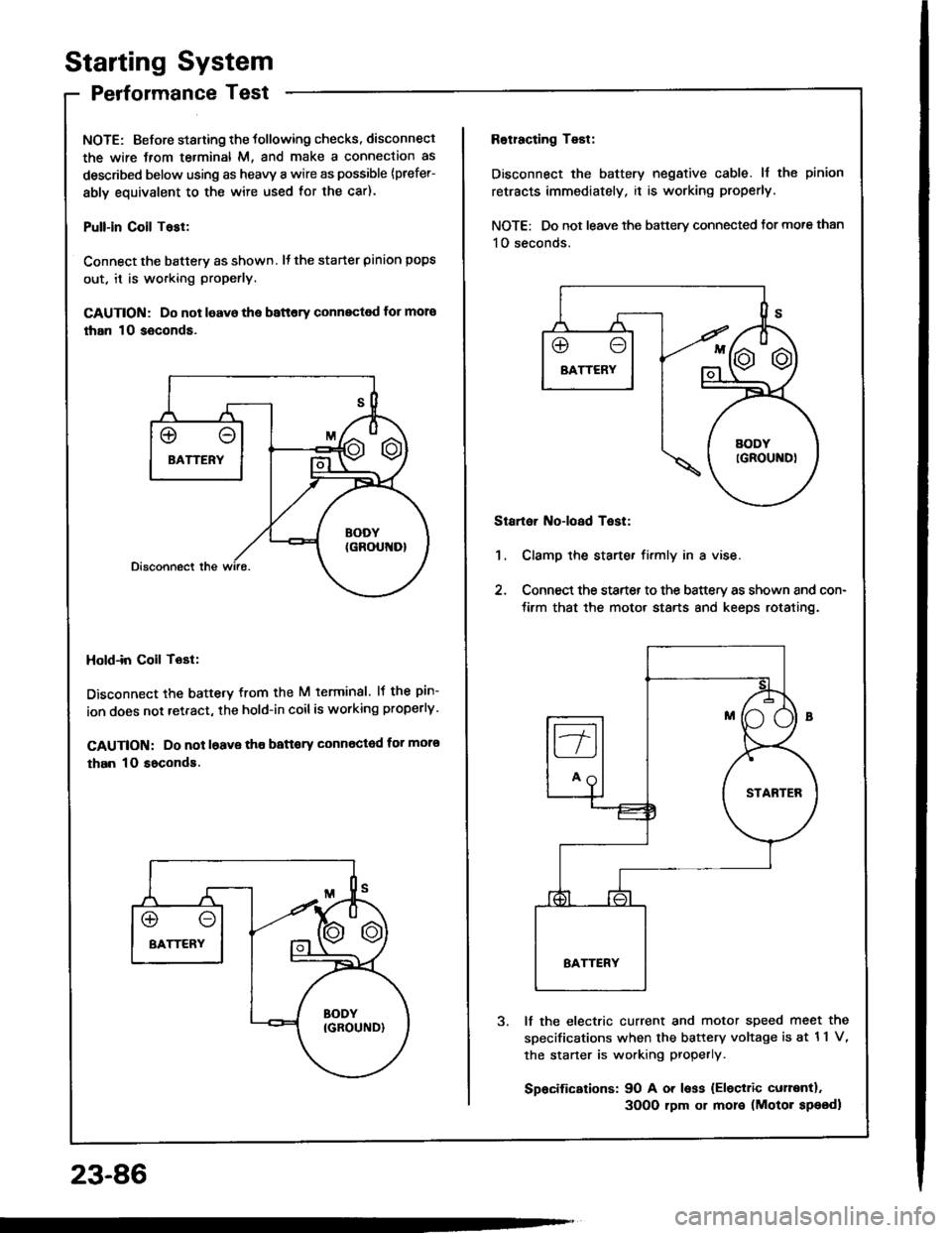
Performance Test
NOTE: Before staning the tollowing checks. disconnect
the wire Jrom te.minal M, and make a connection as
described below using as heavy a wire as possible {prefer-
ably equivalent to the wire used for the car).
Pull-in Coil Tasl:
Connect the batterv as shown. It the starter pinion pops
out, it is working properly.
GAUTION: Do not leavo the battery connectod for mora
than 10 seconds.
Hold-in Coil Tost:
Disconnect the battetv from the M terminal. lf the pin-
ion does not retract, the hold-in coilis working properly.
CAUTION: Do not l6ave tho battory Gonnected for moro
than 10 soconds.
23-86
Rotracting Test:
Disconnect the battery negative cable. ll the pinion
retracts immediately, it is working properly.
NOTE: Do not leave the battery connected tor more than
1O seconds.
Startoi Noioad Test:
1, Clamp the starte. firmly in a vise.
2, Connect the starter to the battery as shown and con-
tirm that the motor starts 8nd keeps rotating.
It the electric current and motor speed meet the
sDecifications when the battery voltage is at 11 V,
the staner is working properly.
Spacifications: 90 A or less {Eleciric curentl.
3OO0 rpm or more (Motor speodl
Page 1197 of 1413
Distributor Top End Inspection
1.
2.
Check for rough or pitted rotor and cap tefminals.
Scrape or file oft the carbon deposits.
Smooth the rotor terminal with an oil stone or #600sandpaper i{ rough.
Check the distributor cap Jor cracks, wear, and
dSmage, lf necessary, clean or replace it.
2
Distributor Removal
1.
2.
Disconnect the 2-P and 8-P connectors from the dis-
tributor.
Disconnect the ignition wires from the distributor
cap.
3. Remove the distributor mounting bolts, then remove
the distributor Irom the cvlinder head.
23-91
Page 1202 of 1413

lgnition
lgnition
System
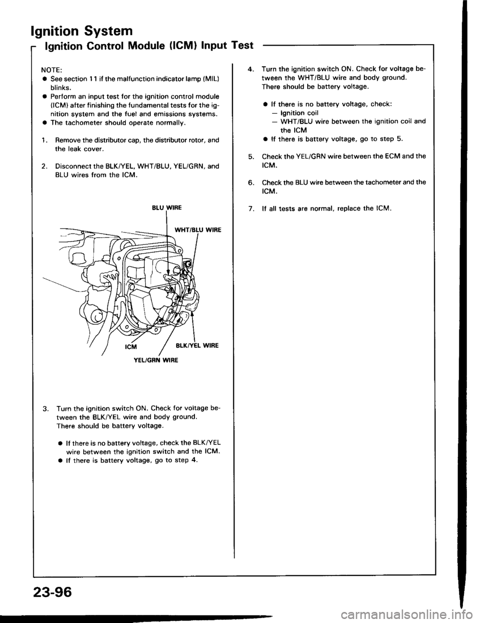
Control Module (lCMl Input Test
NOTE:
a See section I 1 if the malfunction indicator lamD (MlL)
blinks.
a Pertorm an input test for the ignition control module
(lCM) after finishing the fundamental tests for the ig-
nition system and the fuel and emissions systems.
a The tachometer should operate normally.
1. Remove the distributor cap, the distributor rotor, and
the leak cover.
2. Disconnect the BLK/YEL, WHT/BLU, YEL/GRN, and
BLU wires from the lCM.
3. Turn the ignition switch ON. Check for voltage be-
tween the BLK/YEL wire and body ground.
There should be battery voltage.
a lf there is no battery voltage, check the BLK^/EL
wire between the ignition switch and the lCM.
a lf there is battery voltage, go to step 4.
YEL/GRN wlRE
4.Turn the ignition switch ON. Check for voltage be-
tween the WHT/BLU wire and body ground.
There should be battery voltage.
a lf there is no battery voltage, check:- lgnition coil- WHT/BLU wire between the ignition coil and
the ICM
a lf there is battery voltage. go to step 5.
Check the YEL/GRN wire between the ECM and the
tcM.
Check the BLU wi.e between the tachometer and the
rcM.
It all tests are normal, replace the lCM.
6.
7.
23-96
Page 1203 of 1413

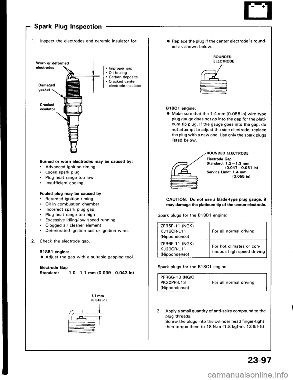
Spark Plug Inspection
1. Inspect the electrodes and ceramic insulator for:
. rmproper gap. Oil-touling. Carbon deposits. Cracked centerelectrode insulatorDamagedgask6t
Burned or worn electlodes may be caused by:. Advanced ignition timing. Loose spark plug. Plug heat range too low. Insufficient cooling
Fouled plug may be caused by:. Retarded ignition timing. Oil in combustion chamber. lncorrect spark plug gap. Plug heat range too high. txcessive idling/low speed running. Clogged air cleaner element. Deteriorated ignition coil or ignition wires
Check the electrode gap.
Bl88l engine:
a Adjust the gap with a suitable gapping tool.
Electrode Gap
Standard: 1.0-1.1 mm (O.O39-0.O43 in)
1.1 mm{0.0,$ in)
Replace the plug if the center electrode is round-
ed as shown below:
ROUNDEDELECTROOE
Bl8Cl engine:
a Make sure that the '1.4 mm (0.055 in) wire-typeplug gauge does not go into the gap for the plati-
num tip plug. lf the gauge goes into the gap, do
not attempt to adjust the side electrode; replace
the plug with a new one. Use only the spark plugs
listed below.
ROUNDEO ELECTRODE
Electrode GapStandard: 1 .2-'l .3 mm{0.047 -O.051 in)Service Limit: 1.4 mm{0.055 in)
CAUTION: Do not use a blade-type plug gaugs, it
may damage the platinum tip of the center olectrodo.
Spark plugs for the 81881 engine:
Spark plugs for the B'l8Cl engine:
PFR6G_13 (NGK) IPK2OPR-113 I For all normal driving
{Nippondenso)
3. Apply a small quantity ol anti-seize compound to the
plug threads.
Screw the plugs into the cylinder head iingef-tight,
then torque them to 18 N.m (1.8 kgf.m, 13lbf.ft).
ZFRsF-1 1 (NGK)
KJl6CR-11 1
(Nippondenso)
For all normal driving
ZFR6F-1 1 (NGK)
KJ2OCR-11 1(Nippondenso)
For hot climates or con-
tinuous high speed driving
23-97
Page 1213 of 1413
Rotor Slip Ring Test
1 . Check thst there is continuity between thg slip rings.
ROTOR SHAFT
Check th8t there is no continuity betw€en the slip
rings and the rotor or rotor shaft.
lf the rotor fails either continuity check, rsplace th€
alternator.
2
3
Stator Test
1. Chock that there is continuity between each pair ofl6ads.
Ch6ck that there is no continuity between each lead
and the coil core.
lf th€ coil fsils either continuity check. replace the
alt6rnator.
cotl coRE
23-107
Page 1228 of 1413

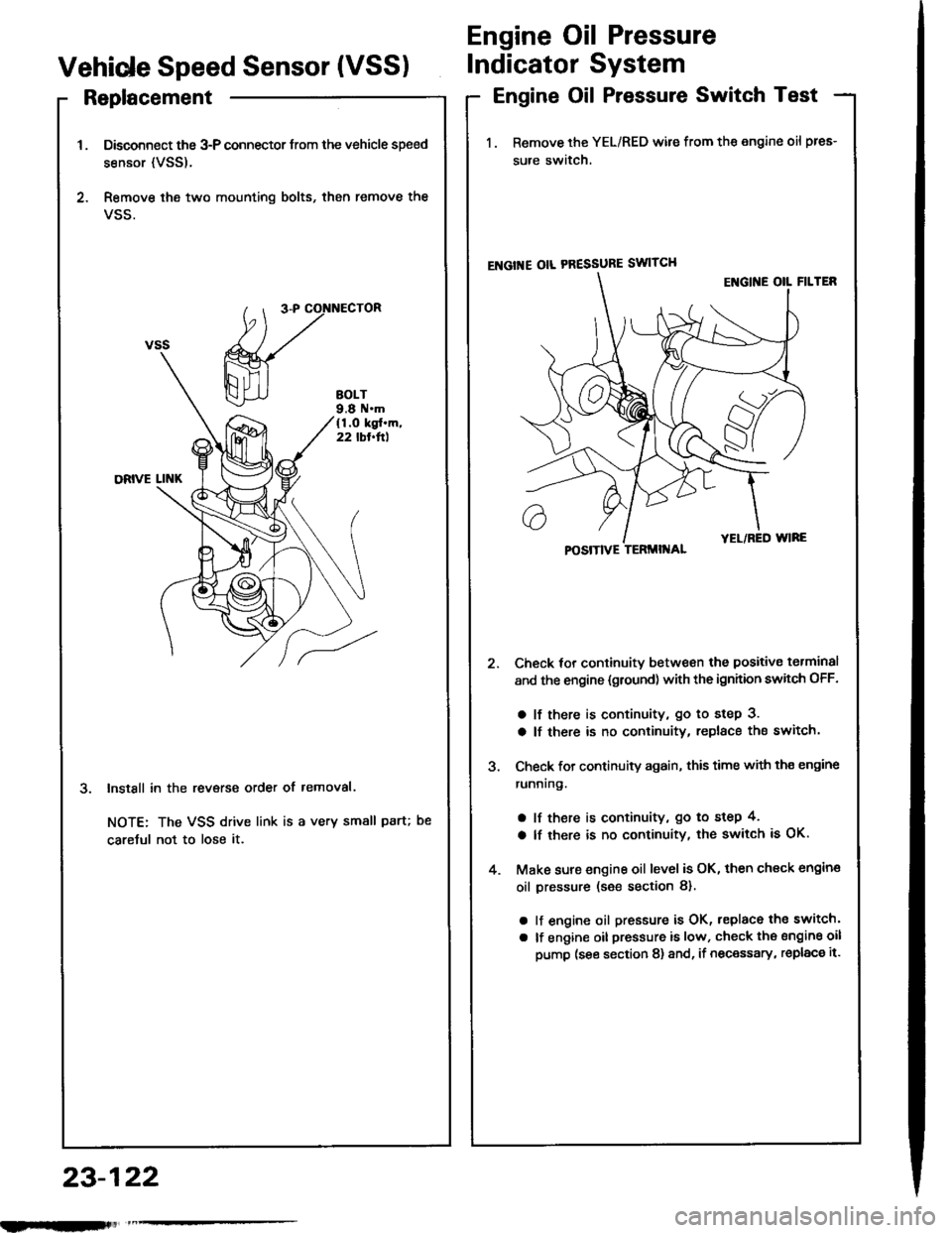
Replacement
Disconnect the 3-P connector trom the vehicle speed
sensor {VSS).
Remove ihe two mounting bolts, then remove the
VSS.
InstSll in the revsrse order of removal.
NOTE: The VSS drive link is a very small paru
caretul not to lose it.
Engine Oil Pressure
Vehide Speed Sensor (VSSIIndicator System
Engine Oil Pressure Switch Test
1. Remove the YEL/RED wile from the engine oil pres-
sure switch.
ENGI'{E OIL PRESSURE SWITCH
Check tor continuitv between the positive torminal
and the engine {gtound) with the ignhion swhch OFF.
a lf there is continuity, go to step 3.
a lf there is no continuity, replace the switch.
Check for continuity again, this time with th€ engine
runnrng.
a lf there is continuity, go to step 4,
a lf there is no continuity, the switch is OK.
Make sure engine oil level is OK, then check engin€
oil pressure (s€e section 8).
a lf engine oil pressure is OK, replace the switch'
a lf engine oil pressure is low, check the sngine oil
pump (see section 8) and, if necessary, replac€ it.
POSITIVE TERMII{AL
23-122
nlmlliitl
Page 1250 of 1413
Integrated Control Unit
Circuit Diagram
D.3c ptlon
An integrat€d control unit, located in the left kick panel, integratss the functions of tho keyin/seat beh r6mind€r, sido
markar light {lasher, wiper/washer, lights-on r6minder, rear window dsfogger timer, brak€ system light bulb check, and
enging oil pressure indicator flasher circuitE,
NOTE: Difforent wires with the same color have be6n given a numbor suffix to distinguish them (for Example,
GRN/RED1 and GRN/RED'� are not the same).
WNOSHIELD WIPER/WASHER SWITCH
IMT OFFiINT
I
II
IIIIIIIIIIII
YEUEE
rl
t
P
UNOER - DASH FUS€/RETAY BOX
r NTEGRATED COI{TROI UNIT
t-0wErGrilE 0|lPRESSI'REINDICATORLIGI{T
WINDSHIELOWIPERAVASHERswtTcH
tr-/
IBLK/GRN BI
WINDSHIELOWIPERMOTOR{Asl
VOLTAGEREGULATOR{ln ahamator,
UNOER- HOOD FUSE/RELAY 8OX
I
r3
r8relit;rBt5I
23-144
lr ) : With combinod washef-wip€r oporation