1993 VOLKSWAGEN GOLF height
[x] Cancel search: heightPage 17 of 156
Downloaded from www.Manualslib.com manuals search engine L-___________________________________________________~~~_CONTROLS AND EQUIPMENT
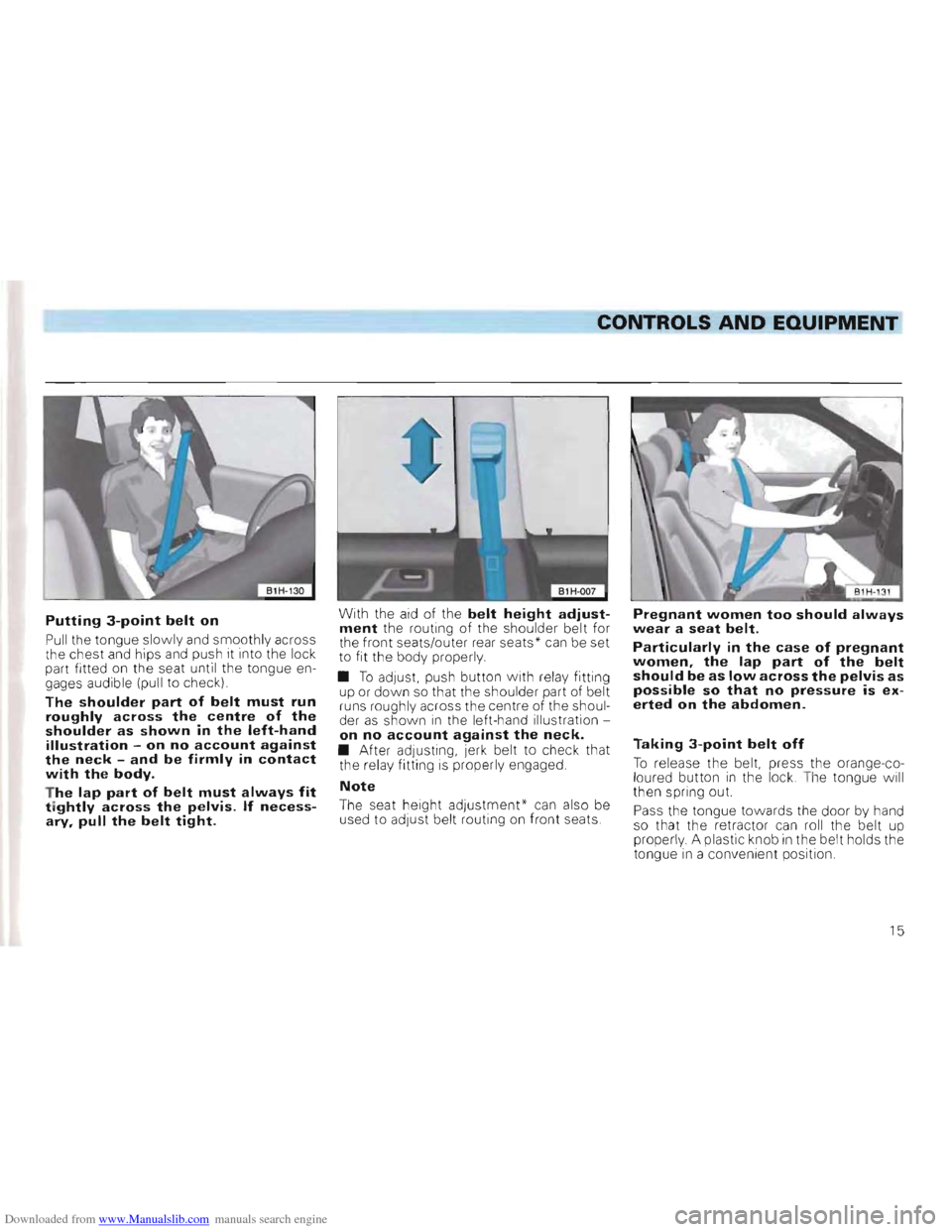
Putting 3-point belt on
Pull the tongue slowly and smoothly across
t he chest and hips and push it into the lock
part fitted on the
seat unti l the tongue en
gages audible (pull to c heck)
The shoulder part of belt must run roughly across the centre of the shoulder as shown in the left-hand illustration -on no account against the neck -and be firmly in contact with the body.
T he lap part of belt must always fit tightly across the pelvis. If necessary, pull the belt tight.
With the aid of the belt height adjustment the routing of the shou lder belt for
the fron t seats/outer rear seat s * can be set
t o fit the body properly.
• T o
adJUSt. push button with re la y fitting
up or down so that the shoulder part of be lt
runs rough ly across the cen tre of the shoul
der as shown i n the le ft-h and illustration on no account against the neck. • After adjustin g, jerk belt to check that
the relay fitting is properly engaged.
Note
The seat height adjustment' can also be
used to adju st be lt routing on front seats.
Pregnant women too should always
wear a seat belt.
Particularly in the case of pregnant
women, the lap part of the belt
should be as low across the pelvis as
possible so that no pressure is ex
erted on the abdomen.
Taking 3-point belt off
To re lease the belt, press the orange-co
l oured button in the lock . T he to ngue will
th en s pring out.
Pass the tongue
towards the door by hand
so that the retractor can roll the belt up
prope
rly . A plastic knob in the belt holds the
t o ngue in a convenient position .
15
Page 21 of 156
Downloaded from www.Manualslib.com manuals search engine ----------------------------------CONTROLS AND EQUIPMENT
•
I 81H-143 I
Function
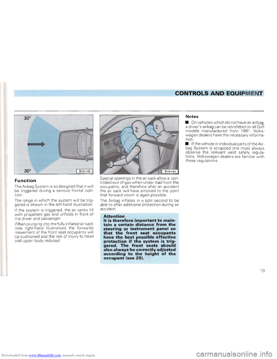
The Airbag System is so designed that it wil l
be triggered during a serious frontal colli
s lon.
The range in which the system will be trig
gered is shown in the left- hand illustrat ion .
If the system
is triggered, the air sacks fill
w ith prop ellant gas and unfolds in front of
t he driver and passenger.
W hen plunging into the full y inflated air sack
(
see right-hand illustration) the forwards
m ovement of the fron t se at occupants will
b e cushioned and the risk of in
jur y to head
a n d upper body reduced. Special
openings
in the air sack allow a con
trolled exit of gas when unde r load from the
occupants, and therefore after
an accident
the air sac k will have emptied to the point
that forward vision is again possible
The Airbag inflates
in a split second to be
able to offer add itional protection during an acc ident.
Attention It is therefore important to maintain a certain distance from the steering or instrument panel so that the front seat occupants have the best possible effective protection if the system is triggered. The front seats should also always be correctly adjusted according to the height of the occupant (see 25).
Notes
• On vehicles which do not have an airbag, a driver'S airbag can be retrofitted on all G olf
models manufactured from 1991. Volks
w agen dealers
have the necessary informa
tion .
• If the vehicle or individual parts of the Air
bag System
is scrap ped one must always
observe the relevant va lid safet y regula
tions. Volkswagen dealers are familiar w ith
these regulations.
19
Page 23 of 156
Downloaded from www.Manualslib.com manuals search engine CONTROLS AND EQUIPMENT
Safety for children
Children under 12 years of age should normally travel on the rear seat1). Depending upon their age, height and weight, they must be protected with either a child restraint system or the seat belt provided. For reasons of safety, the child restraint system should be fitted in the middle of the bench seat or behind the passenger seat.
Attention Children under 1.50 m (5') tall must not use normal seat belts without the child restraint system. This could cause injury to the stomach and neck.
Ob serv e any statutor y regulation s to th e conrary .
Only officially approved ch ild restraint sys
te ms w hich are suitable for the child should
be used.
T he
ECE-R 21 standard 44 app lies to child re
straint systems. This categorizes restraint
systems Into four classes:
Cla ss 0: 0-10 kg
(approx to 9 months)
C lass 1 9
-18 kg
(approx . 8 m onths to 4 years)
Class
2: 15-25 kg
(approx. 3 to 7 yea rs)
Class 3: 22 -36 kg
(approx 6 to 12 years)
Child
restraint systems tested according to
ECE-R standard 44 are clearly marked w ith
the ECE-R test mark 44 (capital E in a Circle,
with test number below) .
Class 0
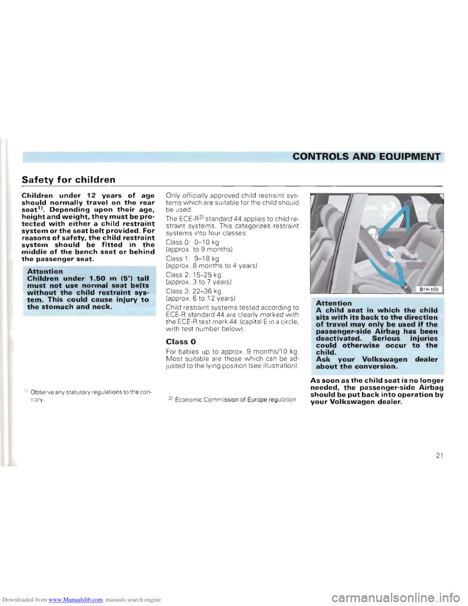
For babies up to app rox . 9 months/10 kg Most suitable are those which can be ad
Justed to the lY ing position (see Illustration)
2) Econom ic Co mission of Europe regulat ion
Attention A child seat in which the child sits with its back to the direction of travel may only be used if the passenger-side Airbag has been deactivated. Serious injuries could otherwise occur to the child. Ask your Volkswagen dealer about the conversion.
As soon as the child seat is no longer needed, the passenger-side Airbag should be put back into operation by your Volkswagen dealer.
21
Page 26 of 156
Downloaded from www.Manualslib.com manuals search engine CONTROLS AND EQUIPMENT
Head restraints*
B1H-168 I
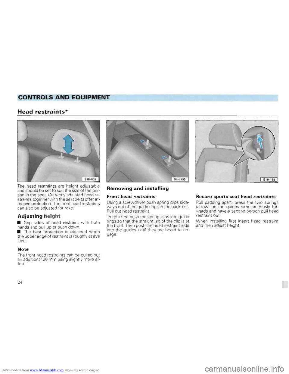
The head restraints are height adjustable and should be set to suit the size of the per
son in the seat. Correctly adjusted head re
straints togeth er with the seat belts offer ef
fective prot ection . The f
ront head restraints can also be adjuste d for rake.
Adjusting height
• Grip sides of head restraint with both
hands and pul l up or push dow n. • The best protection is obtained when
the upper edge of res traint is roughly at eye
l evel.
Note
Th e fr ont head restra ints can be pulled ou t an additional 20 mm using slightly more ef
fort.
Removing and installing
Front head restraints
Using a screwdri ver push spring clips side
ways out of the guide rings in the backrest. Pull out head restraint.
T o refit first push the spring clips into guide
rings so that the straight leg of the clip
is at
the front. Then push the head restraint rods
into the guides until they are heard to en
gage.
Recaro sports seat head restraints
Pull paddi ng apart, press the two springs (arr ow) on the guides simultaneous ly fo rw ards and have a second person pul l head
restraint out.
When installing f
irst insert head restraint and then adjust height.
24
Page 28 of 156
Downloaded from www.Manualslib.com manuals search engine CONTROLS AND EQUIPMENT
2 -Adjusting backrest angle
Take weight off back rest and turn knob.
The backrest of the driv er's seat shou ld be adjusted so that the top of the steerin g
whee l can be reached with the arms angled slightly.
Attention
Do not lower the backrest too far
when on the move because the seat belts are then no longer fully effective.
3 -Releasing backrest
(2 door vehicl es only)
Lif t the
lever (also belt holder) and move the
back rest forward. Before releasing the
backrest pull
belt out of the belt holder (see
page 17).
Attention For safety reasons, ensure that the backrest lock is engaged when the vehicle is moving!
4 -Adjusting angle of the seat
cushion*
If the angle of the seat cushion is to be changed, pull lever up and bring seat
cushion to the desired angle by placing
mo
re or less weight on the backrest.
5 -Adjusting seat height*
Take weight off seat cushion and pull up lever. The whole seat cushion moves up
war ds. To adjust the seat cushion down
w ards, push seat downwards with body
weight.
Attention • For safety reasons the height of the driver's seat must only be adjusted when vehicle is stationary. • Be careful when adjusting the seat height! Careless and uncontrolled adjustment can cause injuries.
6 -Adjusting lumbar support
By turn ing the hand-wheel the seat padding in the lumbar area of the spine can be made
to arch forward slightly. This gives effective
support to the natura l curvatu re of the spine
so that t
he sitting position is less fatigui ng ,
particul arly on long trips
26
Page 37 of 156
Downloaded from www.Manualslib.com manuals search engine CONTROLS AND EQUIPMENT
Height adjustable
steering wheel*
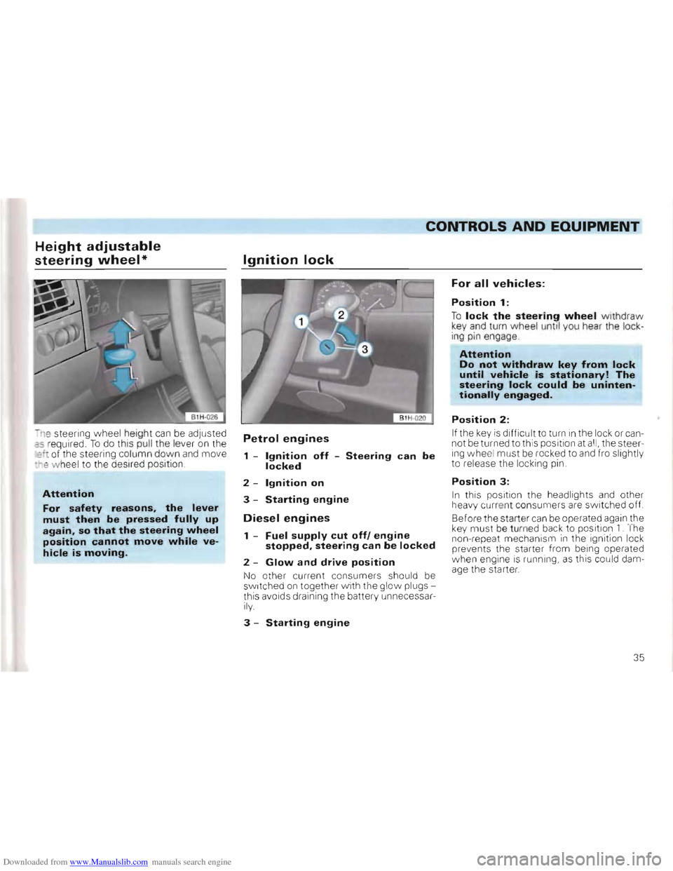
-n e steering wheel height can be adjusted as r equired . To do this pull the lever on the :::1 of th e stee ring co lumn down and move -~e w hee l to the desir ed position
Attention
For safety reasons, the lever
must then be pressed fully up again, so that the steering wheel position cannot move while ve
hicle is moving.
Ignition lock
Petrol engines
1 -Ignition off -Steering can be locked
2 -Ignition on
3 -Starting engine
Diesel engines
1 -Fuel supply cut off! engine stopped, steering can be locked
2 -Glow and drive position
No other current co nsumer s should be sw itc hed on together w ith the glow plugs
this aVOi d s dra ining the batte ry unn ecessa rily.
3 -Starting engine
For all vehicles:
Position 1:
To lock the steering wheel withdraw key and turn wheel unti l you hear the lock
ing pin engage
Attention Do not withdraw key from lock until vehicle is stationary! The steering lock could be unintentionally engaged.
Position 2:
If the key is difficult to turn in the lock or can
not be turned to this position at all, the steer
ing wheel must be rocked to and fro slightly
to release the locking pin .
Position 3:
In this pos ition the headlights and other
h eavy cu rre nt consume rs are switched off.
Before the start er
can be operated again the key must be turned back to position 1. The
non-repeat mechanism in the ignition lock
prevents th e starter from being operated
w hen engine
is ru nning, as this could dam
age the starter.
35
Page 92 of 156
Downloaded from www.Manualslib.com manuals search engine GENERAL MAINTENANCE
Bonnet
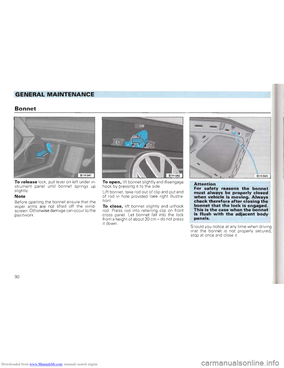
To release lock, pull lever on left under in
strument panel until bonnet springs up slightly.
Note
Before opening the bo nnet ensure that the
wiper arms are not lifted off the wind
screen. Othe rwise damage can occur to the
palntwork. To
open, lift
bonnet slightly and disengage
hook by pressing it to the side.
Lift bonnet, take rod out of
clip
and put end
of rod in hole provided (see right illustra
tion)
To
close, lift bonnet slightly and unhoo k
rod. Press rod into retaining cl ip on front
cross panel. Let bonnet fall into the lock
from a height of about 30 cm -do not press
it down.
B1H -043
Attention For safety reasons the bonnet must always be properly closed when vehicle is moving. Always check therefore after closing the bonnet that the lock is engaged. This is the case when the bonnet is flush with the adiacent body panels.
Should you notice at any time when driving
that the bonnet is not properly secured,
stop at once and close it.
90
Page 110 of 156
Downloaded from www.Manualslib.com manuals search engine GENERAL MAINTENANCE
• Never fit used tyres where their previ
ous history is not known.
• Knowing the tyre lettering and its
meaning makes the selec tion of the correct
t yres easier.
Radial ply tyres have the fol
lowing lettering on the sidewall:
e .
g. 195/50 R 1582 V
195
50
R
15
82
V
Tyre w idth in mm
Height/width ratio in %
Radial construction code letter
= Radial
Wheel diameter
in inches
Carrying capability code
Speed code letter
The manufacturing date is also to be
seen on th e tyre wall (possibly on ly on inner
sid e of wheel):
DOT
... 123 . . means that the tyre was pro
duced in the 12th week of 1993 .
Attention Tyres which are more than 6 years old should only be used in an emergency and then with a particularly careful style of driving.
If you wish to fit your car with nonstandard wheels or tyres please note:
Attention • For technical reasons it is not normally possible to use wheels from other vehicles -in certain circumstances not even wheels from the same vehicle model!
• Using wheels and/or tyres which have not been approved by us for your vehicle model can be detrimental to the safety of the vehicle. It can also affect the vehicle under the Construction and Use regulations.
• If wheel trim discs or a front spoiler are subsequently installed it is essential to ensure that the air flow remains adequate to cool the brakes. • On the BBS alloy wheels with the bolted-on outer ring* the multi-point screws must not be loosened under any circumstances. The wheels could than leak air -Accident danger!
Volkswagen dealers have all the necessary
information about the possible conversion
of wheels, tyres and wheel trims.
108