1993 VOLKSWAGEN CORRADO instrument panel
[x] Cancel search: instrument panelPage 2 of 920

HOW TO USE SYSTEM WIRING DIAGRAMSI - SYSTEM/COMPONENT TESTSINSTRUMENT PANELINTERFERENCE VERIFICATION CHECK FOR OHC ENGINEJ - PIN VOLTAGE CHARTSL - WIRING DIAGRAMSM - VACUUM DIAGRAMSMAINTENANCE INFORMATIONMAINTENANCE REMINDER LIGHT RESET PROCEDURESMETRIC CONVERSIONSMIRRORS - POWERN - REMOVE/INSTALL/OVERHAULP - EGR FUNCTION TESTINGPRE-ALIGNMENT CHECKSRIDING HEIGHT ADJUSTMENTSCHEDULED SERVICESSPECIFICATIONS & ELECTRIC COOLING FANSSTARTERSTEERING COLUMNSTEERING COLUMN SWITCHESSTEERING GEAR - POWER RACK & PINIONSUN ROOF - POWERSUSPENSION - FRONTSUSPENSION - REARSYSTEM WIRING DIAGRAMSTRANSMISSION REMOVAL & INSTALLATION - A/TTRANSMISSION REMOVAL & INSTALLATION - M/TTRANSMISSION SERVICING - A/TTRANSMISSION SERVICING - M/TTROUBLE SHOOTING - BASIC PROCEDURESVR65 ENGINE: AFFIX NEW VACUUM HOSE ROUTING LABELWAVEFORMS - INJECTOR PATTERN TUTORIALWHEEL ALIGNMENT SPECIFICATIONS & PROCEDURESWHEEL ALIGNMENT THEORY/OPERATIONWIPER/WASHER SYSTEMWIRING DIAGRAM SYMBOLSWIRING DIAGRAMSWIRING HARNESS CHAFING MAY CAUSE ENGINE STALL
Page 384 of 920

A/C-HEATER SYSTEM - MANUAL
Article Text (p. 9)
1993 Volkswagen Corrado
For Volkswagen Technical Site: http://vw.belcom.ru
Copyright © 1998 Mitchell Repair Information Company, LLC
Wednesday, March 22, 2000 08:49PM
BLOWER MOTOR
Removal & Installation
Disconnect blower motor harness connector. Depress blower
motor retainer clip and rotate blower motor clockwise to disengage lug
on blower motor from clip. To install, reverse removal procedure.
COMPRESSOR
Removal & Installation
Remove ribbed belt. Discharge A/C system using approved
refrigerant recovery/recycling equipment. Remove hoses and plug.
Remove compressor. To install, reverse removal procedure.
EVAPORATOR & HEATER CORE
Removal & Installation
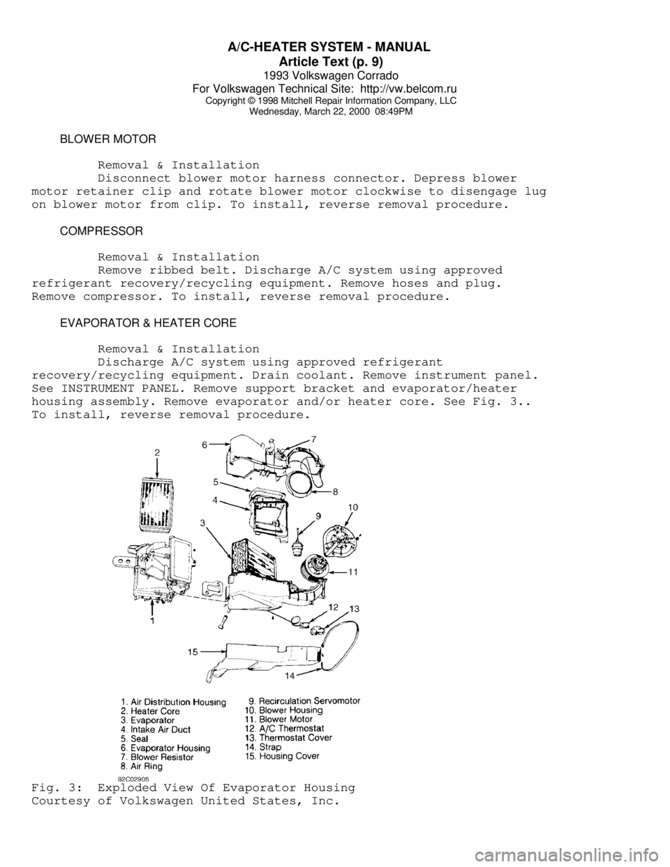
Discharge A/C system using approved refrigerant
recovery/recycling equipment. Drain coolant. Remove instrument panel.
See INSTRUMENT PANEL. Remove support bracket and evaporator/heater
housing assembly. Remove evaporator and/or heater core. See Fig. 3..
To install, reverse removal procedure.Fig. 3: Exploded View Of Evaporator Housing
Courtesy of Volkswagen United States, Inc.
Page 385 of 920

A/C-HEATER SYSTEM - MANUAL
Article Text (p. 10)
1993 Volkswagen Corrado
For Volkswagen Technical Site: http://vw.belcom.ru
Copyright © 1998 Mitchell Repair Information Company, LLC
Wednesday, March 22, 2000 08:49PM
INSTRUMENT PANEL
Removal & Installation
1) Disable air bag system. See AIR BAG SYSTEM SAFETY article
in GENERAL SERVICING. Disconnect battery. Remove storage trays and
panel under left side of instrument panel. Remove steering wheel.
Remove trim panel around instrument cluster.
2) Remove center console. Remove dash vents at each side,
glove box and radio. Remove center storage box, A/C-heater control
panel trim, and A/C-heater control panel screws. Push A/C-heater
control panel away from instrument panel.
3) Remove screws at both sides of instrument panel, at center
support, and 2 screws next to windshield. Detach instrument panel and
pull part way out.
4) Disconnect wiring harnesses from instrument panel.
Disconnect speedometer cable, if present. Remove instrument panel. To
install, reverse removal procedure.
THERMOSTAT
Removal & Installation
1) Remove thermostat cover. See Fig. 3. Remove thermostat
mounting screw and disconnect harness connector. Remove thermostat by
pulling sensing (capillary) tube through grommet.
2) To install, reverse removal procedures. Measure back 13"
(330 mm) from end of sensing tube and tape spot. Insert sensing tube
into evaporator guide channel up to tape.
TORQUE SPECIFICATIONS
TORQUE SPECIFICATIONS TABLEÄÄÄÄÄÄÄÄÄÄÄÄÄÄÄÄÄÄÄÄÄÄÄÄÄÄÄÄÄÄÄÄÄÄÄÄÄÄÄÄÄÄÄÄÄÄÄÄÄÄÄÄÄÄApplication Ft. Lbs. (N.m)
A/C Compressor Bolt/Nut .................... 33 (45)
A/C Compressor Bracket Bolt/Nut ............ 25 (35)
A/C Compressor Hoses
Discharge ................................. 18 (25)
Suction ................................... 25 (35)
ÄÄÄÄÄÄÄÄÄÄÄÄÄÄÄÄÄÄÄÄÄÄÄÄÄÄÄÄÄÄÄÄÄÄÄÄÄÄÄÄÄÄÄÄÄÄÄÄÄÄÄÄÄÄ WIRING DIAGRAMS
Page 398 of 920

ABBREVIATIONS
Article Text (p. 6)
1993 Volkswagen Corrado
For Volkswagen Technical Site: http://vw.belcom.ru
Copyright © 1998 Mitchell Repair Information Company, LLC
Wednesday, March 22, 2000 08:49PM
"H" ABBREVIATION TABLEÚÄÄÄÄÄÄÄÄÄÄÄÄÄÄÄÄÄÂÄÄÄÄÄÄÄÄÄÄÄÄÄÄÄÄÄÄÄÄÄÄÄÄÄÄÄÄÄÄÄÄÄÄÄÄÄÄÄÄÄÄÄÄÄÄÄÄÄÄ¿
³ABBREVIATION
³DEFINITION ³
ÃÄÄÄÄÄÄÄÄÄÄÄÄÄÄÄÄÄÅÄÄÄÄÄÄÄÄÄÄÄÄÄÄÄÄÄÄÄÄÄÄÄÄÄÄÄÄÄÄÄÄÄÄÄÄÄÄÄÄÄÄÄÄÄÄÄÄÄÄ´
³H/D
³Heavy Duty ³
³HAC
³High Altitude Compensation ³
³HC
³Hydrocarbons ³
³HEDF
³High Speed Electro Drive Fan relay or circuit ³
³HEGO
³Heated Exhaust Gas Oxygen Sensor ³
³HEGOG
³HEGO Ground circuit ³
³HEI
³High Energy Ignition ³
³HLDT
³Headlight ³
³HO
³High Output ³
³HP
³High Performance ³
³HSC
³High Swirl Combustion ³
³HSO
³High Specific Output ³
³HTR
³Heater ³
³HVAC
³Heating ³
³Headlt.
³Headlight ³
³Hg
³Mercury ³
³Hgt.
³Height ³
³Htr.
³Heater ³
³Hz
³Hertz (Cycles Per Second) ³
ÀÄÄÄÄÄÄÄÄÄÄÄÄÄÄÄÄÄÁÄÄÄÄÄÄÄÄÄÄÄÄÄÄÄÄÄÄÄÄÄÄÄÄÄÄÄÄÄÄÄÄÄÄÄÄÄÄÄÄÄÄÄÄÄÄÄÄÄÄÙ "I" ABBREVIATION TABLE
"I" ABBREVIATION TABLE
ÚÄÄÄÄÄÄÄÄÄÄÄÄÄÄÄÄÄÂÄÄÄÄÄÄÄÄÄÄÄÄÄÄÄÄÄÄÄÄÄÄÄÄÄÄÄÄÄÄÄÄÄÄÄÄÄÄÄÄÄÄÄÄÄÄÄÄÄÄ¿
³ABBREVIATION
³DEFINITION ³
ÃÄÄÄÄÄÄÄÄÄÄÄÄÄÄÄÄÄÅÄÄÄÄÄÄÄÄÄÄÄÄÄÄÄÄÄÄÄÄÄÄÄÄÄÄÄÄÄÄÄÄÄÄÄÄÄÄÄÄÄÄÄÄÄÄÄÄÄÄ´
³I.D.
³Inside Diameter ³
³IAC
³Idle Air Control ³
³IACV
³Idle Air Control Valve ³
³IC
³Integrated Circuit ³
³ID
³Identification ³
³IDM
³Ignition Diagnostic Monitor ³
³IGN
³Ignition system or circuit ³
³ILC
³Idle Load Compensator ³
³In. Hg
³Inches of Mercury ³
³INCH Lbs.
³Inch Pounds ³
³INFL REST
³Inflatable Restraint ³
³INJ
³Injector or Injection ³
³IP
³Instrument Panel ³
³IPC
³Instrument Panel Cluster ³
³ISA
³Idle Speed Actuator ³
³ISC
³Idle Speed Control ³
³ISS
³Idle Stop Solenoid ³
³ITS
³Idle Tracking Switch ³
³IVSV
³Idle Vacuum Switching Valve ³
³Ign.
³Ignition ³
³In.
³Inches ³
Page 412 of 920

ANTI-LOCK BRAKE SYSTEM
Article Text (p. 2)
1993 Volkswagen Corrado
For Volkswagen Technical Site: http://vw.belcom.ru
Copyright © 1998 Mitchell Repair Information Company, LLC
Wednesday, March 22, 2000 08:57PM
to protect the hydraulic modulator and ECU.
NOTE: For more brake system information, see BRAKE SYSTEM
article in the BRAKES section.
OPERATION
When pressure is applied to brake pedal, ECU monitors input
signals from each wheel speed sensor. If ECU measures a rate of
reduction greater than what is programmed in ECU, the ECU will output
a signal to appropriate solenoid valve. Each solenoid valve allows
hydraulic pressure to increase or decrease to the appropriate wheel
cylinder.
If a system failure occurs, ANTILOCK warning light, located
on instrument panel, will come on. System will be deactivated, but
conventional brake system will still operate. If brake fluid level
drops too low, BRAKE warning light, located on instrument panel, will
come on.
CAUTION: See ANTI-LOCK BRAKE SAFETY PRECAUTIONS in this article.
CAUTION: The ABS system is under extremely high pressure. Depressurize
the brake system before loosening or removing any hydraulic
component.
DEPRESSURIZING BRAKE SYSTEM
Turn ignition off. Depress and release brake pedal 25-35
times, or until there is a noticeable increase in the effort to
depress the brake pedal. DO NOT turn ignition on until all hydraulic
lines and components are fully tighten.
BLEEDING BRAKE SYSTEM
FRONT BRAKES
Depressurize brake system. See DEPRESSURIZING BRAKE SYSTEM.
Connect a container with hose to left front bleeder screw. Have
assistant depress and release brake pedal a few times. Holding brake
pedal down, open bleeder screw and allow fluid to enter container.
Close bleeder screw and then release brake pedal. Continue this method
until no air is present in fluid. Check master cylinder fluid level to
make sure it does not go below minimum level mark. Use same procedure
for right front brake.
REAR BRAKES
CAUTION: When bleeding rear brakes, accumulator pressure (about 3100
psi) is used to assist in procedure. Use eye protection when
performing this procedure. DO NOT allow pump to run longer
than 2 minutes. See ANTI-LOCK BRAKE SAFETY PRECAUTIONS in
Page 456 of 920

CRUISE CONTROL SYSTEM
Article Text (p. 4)
1993 Volkswagen Corrado
For Volkswagen Technical Site: http://vw.belcom.ru
Copyright © 1998 Mitchell Repair Information Company, LLC
Wednesday, March 22, 2000 08:58PM
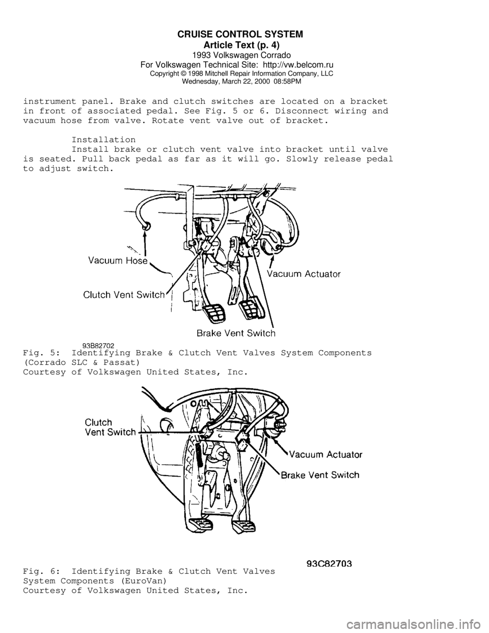
instrument panel. Brake and clutch switches are located on a bracket
in front of associated pedal. See Fig. 5 or 6. Disconnect wiring and
vacuum hose from valve. Rotate vent valve out of bracket.
Installation
Install brake or clutch vent valve into bracket until valve
is seated. Pull back pedal as far as it will go. Slowly release pedal
to adjust switch.Fig. 5: Identifying Brake & Clutch Vent Valves System Components
(Corrado SLC & Passat)
Courtesy of Volkswagen United States, Inc.Fig. 6: Identifying Brake & Clutch Vent Valves
System Components (EuroVan)
Courtesy of Volkswagen United States, Inc.
Page 579 of 920

FUSES & CIRCUIT BREAKERS
Article Text
1993 Volkswagen Corrado
For Volkswagen Technical Site: http://vw.belcom.ru
Copyright © 1998 Mitchell Repair Information Company, LLC
Wednesday, March 22, 2000 09:11PM
ARTICLE BEGINNING
1990-94 ELECTRICAL
Volkswagen Fuses & Circuit Breakers
Corrado
FUSES & CIRCUIT BREAKERS
FUSE PANEL LOCATION
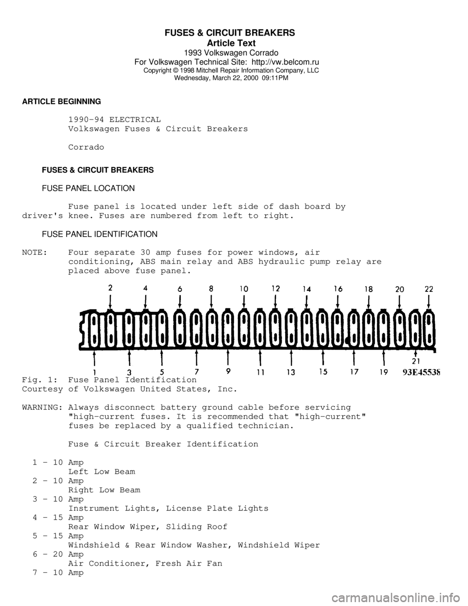
Fuse panel is located under left side of dash board by
driver's knee. Fuses are numbered from left to right.
FUSE PANEL IDENTIFICATION
NOTE: Four separate 30 amp fuses for power windows, air
conditioning, ABS main relay and ABS hydraulic pump relay are
placed above fuse panel.Fig. 1: Fuse Panel Identification
Courtesy of Volkswagen United States, Inc.
WARNING: Always disconnect battery ground cable before servicing
"high-current fuses. It is recommended that "high-current"
fuses be replaced by a qualified technician.
Fuse & Circuit Breaker Identification
1 - 10 Amp
Left Low Beam
2 - 10 Amp
Right Low Beam
3 - 10 Amp
Instrument Lights, License Plate Lights
4 - 15 Amp
Rear Window Wiper, Sliding Roof
5 - 15 Amp
Windshield & Rear Window Washer, Windshield Wiper
6 - 20 Amp
Air Conditioner, Fresh Air Fan
7 - 10 Amp
Page 608 of 920

HOW TO USE SYSTEM WIRING DIAGRAMS
Article Text (p. 5)
1993 Volkswagen Corrado
For Volkswagen Technical Site: http://vw.belcom.ru
Copyright © 1998 Mitchell Repair Information Company, LLC
Wednesday, March 22, 2000 09:11PM
Body Control Module .......................... Body Control Computer
Anti-Theft System
Daytime Running Lights
Engine Performance
Headlight Systems
Warning Systems
Boost Control Solenoid .......................... Engine Performance
Boost Sensor .................................... Engine Performance
Brake Fluid Level Switch .................. Analog Instrument Panels
Brake On/Off (BOO) Switch ................... Cruise Control Systems
Engine Performance
Shift Interlock Systems
Buzzer Module ...................................... Warning Systems
Camshaft Position (CMP) Sensor .................. Engine Performance
Central Control Module ........................... Anti-Theft System
Clockspring ............................... Air Bag Restraint System
Cruise Control Systems
Steering Column Switches
Clutch Pedal Position Switch .............................. Starters
Clutch Start Switch ....................................... Starters
Combination Meter ......................... Analog Instrument Panels
Constant Control Relay Module (CCRM) ............ Engine Performance
Electric Cooling Fans
Convenience Center .............................. Power Distribution
Illumination/Interior Lights
Convertible Top Motor ........................ Power Convertible Top
Convertible Top Switch ....................... Power Convertible Top
Crankshaft Position (CKP) Sensor ................ Engine Performance
Cruise Control Module ....................... Cruise Control Systems
Cruise Control Switch ....................... Cruise Control Systems
Condenser Fan Relay(s) ....................... Electric Cooling Fans
Data Link Connector (DLC) ....................... Engine Performance
Daytime Running Lights Module ............... Daytime Running Lights
Exterior Lights
Defogger Relay ................................ Rear Window Defogger
Diagnostic Energy Reserve Module (DERM) ... Air Bag Restraint System
Discriminating Sensor (Air Bag) ........... Air Bag Restraint System
Distributor ..................................... Engine Performance
Door Lock Actuators ............................... Power Door Locks
Remote Keyless Entry
Door Lock Relay(s) ................................ Power Door Locks
Electrochromic Mirror ................................ Power Mirrors
Electronic Level Control (ELC)
Height Sensor .............................. Electronic Suspension
Electronic Level Control (ELC) Module ........ Electronic Suspension
Engine Coolant Temperature (ECT)
Sending Unit ............................ Analog Instrument Panels
Engine Coolant Temperature (ECT) Sensor ......... Engine Performance
Engine Control Module ........................... Engine Performance
Generators & Regulators
Starters
ETACS ECU .......................................... Warning Systems