1993 VOLKSWAGEN CORRADO instrument panel
[x] Cancel search: instrument panelPage 624 of 920

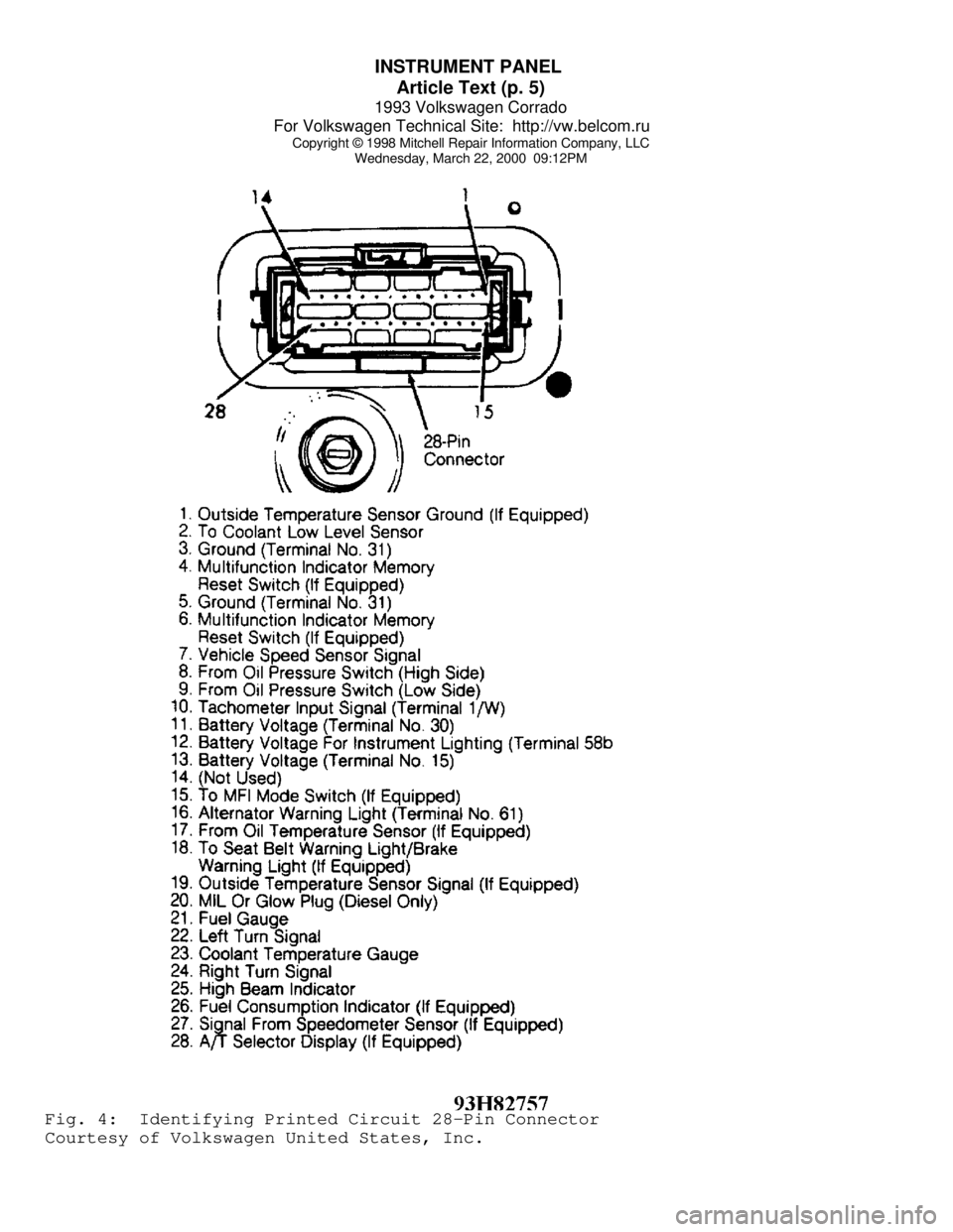
INSTRUMENT PANEL
Article Text (p. 5)
1993 Volkswagen Corrado
For Volkswagen Technical Site: http://vw.belcom.ru
Copyright © 1998 Mitchell Repair Information Company, LLC
Wednesday, March 22, 2000 09:12PMFig. 4: Identifying Printed Circuit 28-Pin Connector
Courtesy of Volkswagen United States, Inc.
Page 625 of 920

INSTRUMENT PANEL
Article Text (p. 6)
1993 Volkswagen Corrado
For Volkswagen Technical Site: http://vw.belcom.ru
Copyright © 1998 Mitchell Repair Information Company, LLC
Wednesday, March 22, 2000 09:12PM
WIRING DIAGRAMS
See appropriate chassis wiring diagram in WIRING DIAGRAMS.
END OF ARTICLE
Page 669 of 920

MAINTENANCE REMINDER LIGHT RESET PROCEDURES
Article Text
1993 Volkswagen Corrado
For Volkswagen Technical Site: http://vw.belcom.ru
Copyright © 1998 Mitchell Repair Information Company, LLC
Wednesday, March 22, 2000 09:20PM
ARTICLE BEGINNING
1983-96 MAINTENANCE
Volkswagen Maintenance Reminder Light Reset Procedures
EGR MAINTENANCE LIGHT (IF EQUIPPED)
EGR light comes on at 15,000 mile intervals to indicate EGR
servicing is required. After checking EGR system, reset mileage
counter. See RESETTING MILEAGE COUNTER.
OXYGEN SENSOR WARNING LIGHT (IF EQUIPPED)
Oxygen sensor (OXS) light comes on at 30,000 mile intervals
to indicate oxygen sensor replacement. After installing new sensor,
reset mileage counter. See RESETTING MILEAGE COUNTER.
RESETTING MILEAGE COUNTER (IF EQUIPPED)
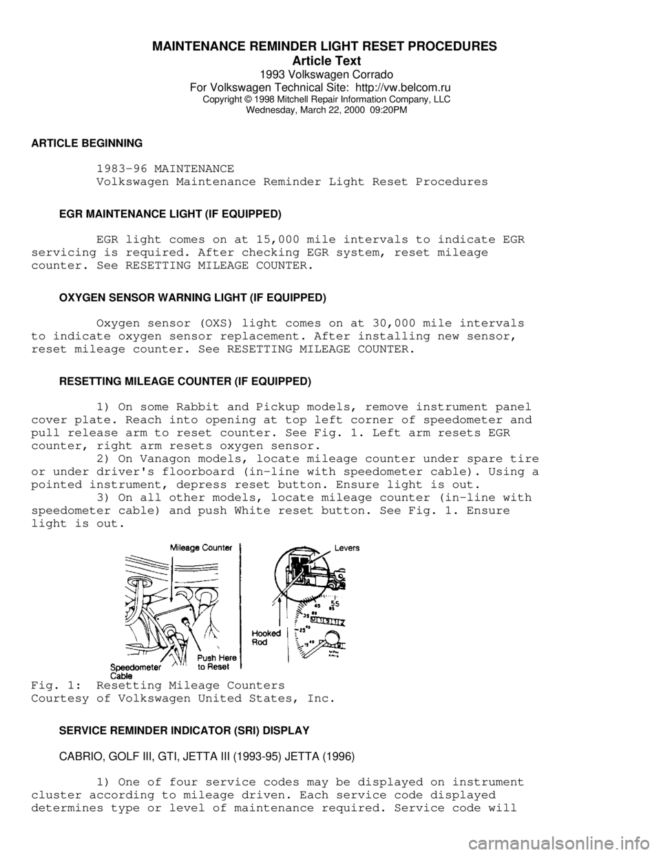
1) On some Rabbit and Pickup models, remove instrument panel
cover plate. Reach into opening at top left corner of speedometer and
pull release arm to reset counter. See Fig. 1. Left arm resets EGR
counter, right arm resets oxygen sensor.
2) On Vanagon models, locate mileage counter under spare tire
or under driver's floorboard (in-line with speedometer cable). Using a
pointed instrument, depress reset button. Ensure light is out.
3) On all other models, locate mileage counter (in-line with
speedometer cable) and push White reset button. See Fig. 1. Ensure
light is out.Fig. 1: Resetting Mileage Counters
Courtesy of Volkswagen United States, Inc.
SERVICE REMINDER INDICATOR (SRI) DISPLAY
CABRIO, GOLF III, GTI, JETTA III (1993-95) JETTA (1996)
1) One of four service codes may be displayed on instrument
cluster according to mileage driven. Each service code displayed
determines type or level of maintenance required. Service code will
Page 733 of 920

STEERING COLUMN
Article Text (p. 2)
1993 Volkswagen Corrado
For Volkswagen Technical Site: http://vw.belcom.ru
Copyright © 1998 Mitchell Repair Information Company, LLC
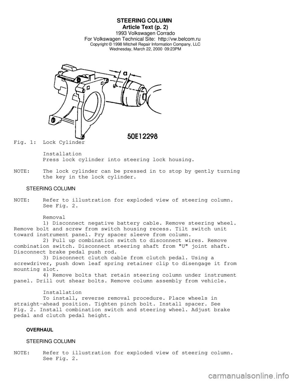
Wednesday, March 22, 2000 09:23PMFig. 1: Lock Cylinder
Installation
Press lock cylinder into steering lock housing.
NOTE: The lock cylinder can be pressed in to stop by gently turning
the key in the lock cylinder.
STEERING COLUMN
NOTE: Refer to illustration for exploded view of steering column.
See Fig. 2.
Removal
1) Disconnect negative battery cable. Remove steering wheel.
Remove bolt and screw from switch housing recess. Tilt switch unit
toward instrument panel. Pry spacer sleeve from column.
2) Pull up combination switch to disconnect wires. Remove
combination switch. Disconnect steering shaft from "U" joint shaft.
Disconnect brake pedal push rod.
3) Disconnect clutch cable from clutch pedal. Using a
screwdriver, push down leaf spring retainer clip to disengage it from
mounting slot.
4) Remove bolts that retain steering column under instrument
panel. Drill out shear bolts. Remove column assembly from vehicle.
Installation
To install, reverse removal procedure. Place wheels in
straight-ahead position. Tighten pinch bolt. Install spacer. See
Fig. 2. Install combination switch and steering wheel. Adjust brake
pedal and clutch pedal height.
OVERHAUL
STEERING COLUMN
NOTE: Refer to illustration for exploded view of steering column.
See Fig. 2.
Page 735 of 920

STEERING COLUMN
Article Text (p. 4)
1993 Volkswagen Corrado
For Volkswagen Technical Site: http://vw.belcom.ru
Copyright © 1998 Mitchell Repair Information Company, LLC
Wednesday, March 22, 2000 09:23PM
notch with lower "U" joint slot. Install boot and damping grommet. Fit
steering box to frame while guiding pinion shaft into lower "U" joint.
2) Hand-tighten steering gear retaining nuts. Place wheels in
straight-ahead position. Align pinion shaft and "U" joint. Tighten
pinch bolt. Tighten steering gear retaining nuts. Connect gearshift
linkage. Check linkage for smooth operation.
TORQUE SPECIFICATIONS
TORQUE SPECIFICATIONS TABLEÄÄÄÄÄÄÄÄÄÄÄÄÄÄÄÄÄÄÄÄÄÄÄÄÄÄÄÄÄÄÄÄÄÄÄÄÄÄÄÄÄÄÄÄÄÄÄÄÄÄÄÄÄÄÄÄÄÄÄÄApplication Ft. Lbs. (N.m)
Pinch Bolt ....................................... 22 (30)
Steering Column-To-Instrument Panel
Retaining Bolt ................................. 15 (20)
Shear Bolt ........................................ (1)
Steering Gear Retaining Nut ...................... 22 (30)
Steering Wheel Nut ................................. 30 (40)
INCH Lbs. (N.m)
Air Bag Unit-To-Steering Wheel Screws .............. 89 (10)
(1) - Tighten until bolt head snaps off.
ÄÄÄÄÄÄÄÄÄÄÄÄÄÄÄÄÄÄÄÄÄÄÄÄÄÄÄÄÄÄÄÄÄÄÄÄÄÄÄÄÄÄÄÄÄÄÄÄÄÄÄÄÄÄÄÄÄÄÄÄEND OF ARTICLE
Page 772 of 920

VR65 ENGINE: AFFIX NEW VACUUM HOSE ROUTING LABEL
Article Text (p. 13)
1993 Volkswagen Corrado
For Volkswagen Technical Site: http://vw.belcom.ru
Copyright © 1998 Mitchell Repair Information Company, LLC
Wednesday, March 22, 2000 09:26PM
Prolonged chaffing could result in an electrical short causing either
the engine to stall or the radiator fan to stop operating which could
cause overheating of the engine. Either condition could cause
overheating of the engine of the engine. Either condition could cause
an accident.
Additionally, an incorrect vacuum hose routing label was inadvertently
affixed in the engine compartment of your vehicle.
Remedy
Your Volkswagen retailer will re-route and secure the affected wiring
harness in the engine compartment with a new vacuum hose routing
label.
Your Action
We ask that you contact the Service Department of your authorized
Volkswagen retail facility to schedule an appointment as soon as
possible. Please present the enclosed Campaign authorization form when
you arrive. The required work will take approximately two hours and
will, of course, be free of charge. Necessary instructions and parts
are available at Volkswagen retail facilities.
Precaution
Prior to having your vehicle repaired, please observe the water
temperature warning light located on the instrument panel. Should the
temperature warning light activate while driving the vehicle, contact
your nearest authorized Volkswagen retail facility immediately.
Service Problem Help
If your Volkswagen retailer fails or is unable to remedy the defect
free of charge within a reasonable time, please call or write to:
Volkswagen of America, Inc.
Att'n.: Customer Relations - 2F02
3800 Hamlin Road
Auburn Hill, MI 48326
Toll-free Telephone: 1-800-822-8987
If you still cannot obtain satisfaction, you may file a complaint
with: Administrator, National Highway Traffic Safety Administration,
U.S. Department of Transportation,400 Seventh St. SW, Washington D.C.
20590. Telephone: 1 (800) 424-9393 (Washington, DC area: (366-0123).
We regret any inconvenience this matter may cause; however, as part
of our commitment to maintain your safety and satisfaction with our
product, we want to make sure that your Corrado is repaired as soon as
possible.
Page 842 of 920

TROUBLE SHOOTING - BASIC PROCEDURES
Article Text (p. 51)
1993 Volkswagen Corrado
For Volkswagen Technical Site: http://vw.belcom.ru
Copyright © 1998 Mitchell Repair Information Company, LLC
Wednesday, March 22, 2000 09:26PM
shield
Tight steering universal See STEERING COLUMN
joint articleÄÄÄÄÄÄÄÄÄÄÄÄÄÄÄÄÄÄÄÄÄÄÄÄÄÄÄÄÄÄÄÄÄÄÄÄÄÄÄÄÄÄÄÄÄÄÄÄÄÄÄÄÄÄÄÄÄÄÄÄÄÄÄÄÄHigh Shift Column is out of See STEERING COLUMN
Effort alignment article
Improperly installed Adjust or replace
dust shield
Seals or bearings not See STEERING COLUMNS
lubricated article
Mounting bracket screws Replace with new
too long shorter screws
Burrs on shift tube Remove burrs or replace
tube
Lower bowl bearing See STEERING COLUMN
assembled wrong article
Shift tube bent or broken Replace as necessary
Improper adjustment of See STEERING COLUMN
shift levers article
ÄÄÄÄÄÄÄÄÄÄÄÄÄÄÄÄÄÄÄÄÄÄÄÄÄÄÄÄÄÄÄÄÄÄÄÄÄÄÄÄÄÄÄÄÄÄÄÄÄÄÄÄÄÄÄÄÄÄÄÄÄÄÄÄÄImproper Trans. Sheared shift tube joint Replace as necessary
Shifting
Sheared lower shaft lever Replace as necessary
Improper shift lever See STEERING COLUMN
adjustment article
Improper gate plate See STEERING COLUMN
adjustment article
ÄÄÄÄÄÄÄÄÄÄÄÄÄÄÄÄÄÄÄÄÄÄÄÄÄÄÄÄÄÄÄÄÄÄÄÄÄÄÄÄÄÄÄÄÄÄÄÄÄÄÄÄÄÄÄÄÄÄÄÄÄÄÄÄÄExcess Play in Instrument panel bracket Tighten bolts and check
Column bolts loose bracket
Broken weld nut on jacket See STEERING COLUMN
article
Instrument bracket capsule See STEERING COLUMN
sheared article
Column bracket/jacket Tighten bolts and check
bolts loose bracket
ÄÄÄÄÄÄÄÄÄÄÄÄÄÄÄÄÄÄÄÄÄÄÄÄÄÄÄÄÄÄÄÄÄÄÄÄÄÄÄÄÄÄÄÄÄÄÄÄÄÄÄÄÄÄÄÄÄÄÄÄÄÄÄÄÄSteering Locks Release lever mechanism See STEERING COLUMN
in Gear article
Page 907 of 920

WIRING DIAGRAMS
Article Text
1993 Volkswagen Corrado
For Volkswagen Technical Site: http://vw.belcom.ru
Copyright © 1998 Mitchell Repair Information Company, LLC
Wednesday, March 22, 2000 09:28PM
ARTICLE BEGINNING
1993 WIRING DIAGRAMS
Volkswagen Wiring Diagrams
Volkswagen; Corrado
COMPONENT LOCATION MENU
COMPONENT LOCATIONS TABLEÄÄÄÄÄÄÄÄÄÄÄÄÄÄÄÄÄÄÄÄÄÄÄÄÄÄÄÄÄÄÄÄÄÄÄÄÄÄÄÄÄÄÄÄÄÄÄÄÄÄÄÄÄÄÄÄÄÄÄÄÄÄÄÄÄComponent Figure No. (Location)
A/C COMPRESSOR CLUTCH ................................. 7 (C 3)
A/C PRESSER SWITCH .................................... 1 (C 1)
A/C SWITCH ........................................ 6 (E 20
Ä21)
ABS CONTROL UNIT .................................. 4 (B 12-14)
ABS DIAGNOSTIC CONNECTOR ............................. 4 (D 15)
ABS HYDRAULIC PUMP FUSE .............................. 4 (E 15)
ABS VALVE FUSE ....................................... 4 (A 12)
ABS WARNING SWITCHES ................................. 4 (B 15)
ALTERNATOR ............................................ 1 (B 3)
ANTI-THEFT ALARM CONTROL UNIT ......................... 3 (E 8)
BACK-UP LIGHT SWITCH ........................... 9,10 (E 32
Ä39)
BATTERY ............................................... 1 (A 2)
BEAM SELECT SWITCH ................................... 6 (A 20)
BRAKE FLUID LEVEL SWITCH ............................. 8 (A 31)
CENTRAL LOCK CONTROL UNIT ........................... 10 (A 39)
CIGARETTE LIGHTER AND LIGHT .......................... 7 (A 24)
COOLANT FAN CONTROL/COOLANT TEMPERATURE SENDER UNIT ... 1 (D 1)
COOLANT TEMPERATURE SENDER (EXCEPT SLC) .............. 8 (A 29)
CRUISE CONTROL UNIT ............................... 4 (A 12
Ä15)
DEFOGGER SWITCH ...................................... 8 (E 29)
DIRECTIONAL HAZARD SWITCH ............................ 6 (A 21)
DOOR SWITCHES ....................................... 10 (B 38)
ENGINE CONTROL MODULE (ECM)(SLC) .................... 2 (A
ÄE 7)
FOG LIGHT SWITCH ..................................... 6 (A 23)
FRESH AIR SWITCH ............................. 6,9 (E 22, E 32)
FRESH AIR SWITCH ILLUMINATION LIGHT .................. 6 (D 20)
FUEL INJECTORS ........................................ 2 (D 4)
FUEL TANK SENDER ..................................... 5 (E 18)
FUSE #23 ............................................. 6 (D 20)
FUSE #51 ............................................. 9 (D 34)
FUSE/RELAY PANEL ............................... 5,8 (C 16, 31)
FUSE/RELAY PANEL LAYOUT ...................... 10 (D, E 37, 39)
GLOVE COMPARTMENT LIGHT .......................... 9 (D 30, 31)
HYDRAULIC PUMP RELAY ............................... 5 (D-E 15)
HYDRAULIC UNIT .................................... 5 (E 17
Ä15)
IGNITION COIL ......................................... 2 (E 6)
IGNITION SWITCH ...................................... 5 (A 16)
INSTRUMENT CLUSTER .............................. 9 (A
ÄD 32Ä34)
INTERIOR LIGHT SWITCH ............................... 11 (E 41)