1993 VOLKSWAGEN CORRADO clutch
[x] Cancel search: clutchPage 348 of 920
A/C COMPRESSOR SERVICING
Article Text (p. 12)
1993 Volkswagen Corrado
For Volkswagen Technical Site: http://vw.belcom.ru
Copyright © 1998 Mitchell Repair Information Company, LLC
Wednesday, March 22, 2000 08:48PM
open end of front cover. Slowly pull out remover/installer to remove
shaft seal.
Installation
1) Ensure shaft seal contact surface is free of dirt.
Lubricate with refrigerant oil. Using shaft seal remover/installer,
insert shaft seal.
2) To install clutch coil and hub, reverse removal procedure.
Tighten shaft nut to 14-15 ft. lbs. (19-21 N.m). Ensure clearance
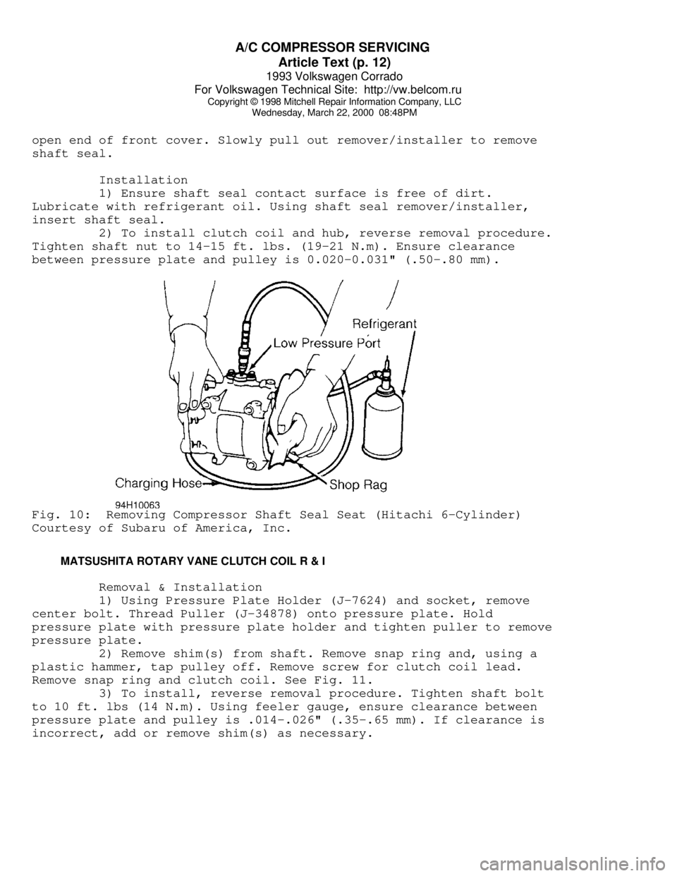
between pressure plate and pulley is 0.020-0.031" (.50-.80 mm).Fig. 10: Removing Compressor Shaft Seal Seat (Hitachi 6-Cylinder)
Courtesy of Subaru of America, Inc.
MATSUSHITA ROTARY VANE CLUTCH COIL R & I
Removal & Installation
1) Using Pressure Plate Holder (J-7624) and socket, remove
center bolt. Thread Puller (J-34878) onto pressure plate. Hold
pressure plate with pressure plate holder and tighten puller to remove
pressure plate.
2) Remove shim(s) from shaft. Remove snap ring and, using a
plastic hammer, tap pulley off. Remove screw for clutch coil lead.
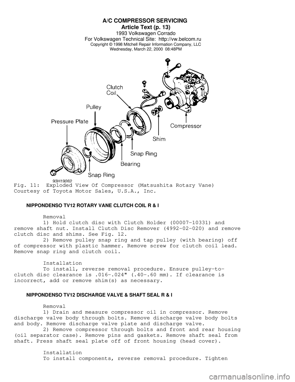
Remove snap ring and clutch coil. See Fig. 11.
3) To install, reverse removal procedure. Tighten shaft bolt
to 10 ft. lbs (14 N.m). Using feeler gauge, ensure clearance between
pressure plate and pulley is .014-.026" (.35-.65 mm). If clearance is
incorrect, add or remove shim(s) as necessary.
Page 349 of 920
A/C COMPRESSOR SERVICING
Article Text (p. 13)
1993 Volkswagen Corrado
For Volkswagen Technical Site: http://vw.belcom.ru
Copyright © 1998 Mitchell Repair Information Company, LLC
Wednesday, March 22, 2000 08:48PMFig. 11: Exploded View Of Compressor (Matsushita Rotary Vane)
Courtesy of Toyota Motor Sales, U.S.A., Inc.
NIPPONDENSO TV12 ROTARY VANE CLUTCH COIL R & I
Removal
1) Hold clutch disc with Clutch Holder (00007-10331) and
remove shaft nut. Install Clutch Disc Remover (4992-02-020) and remove
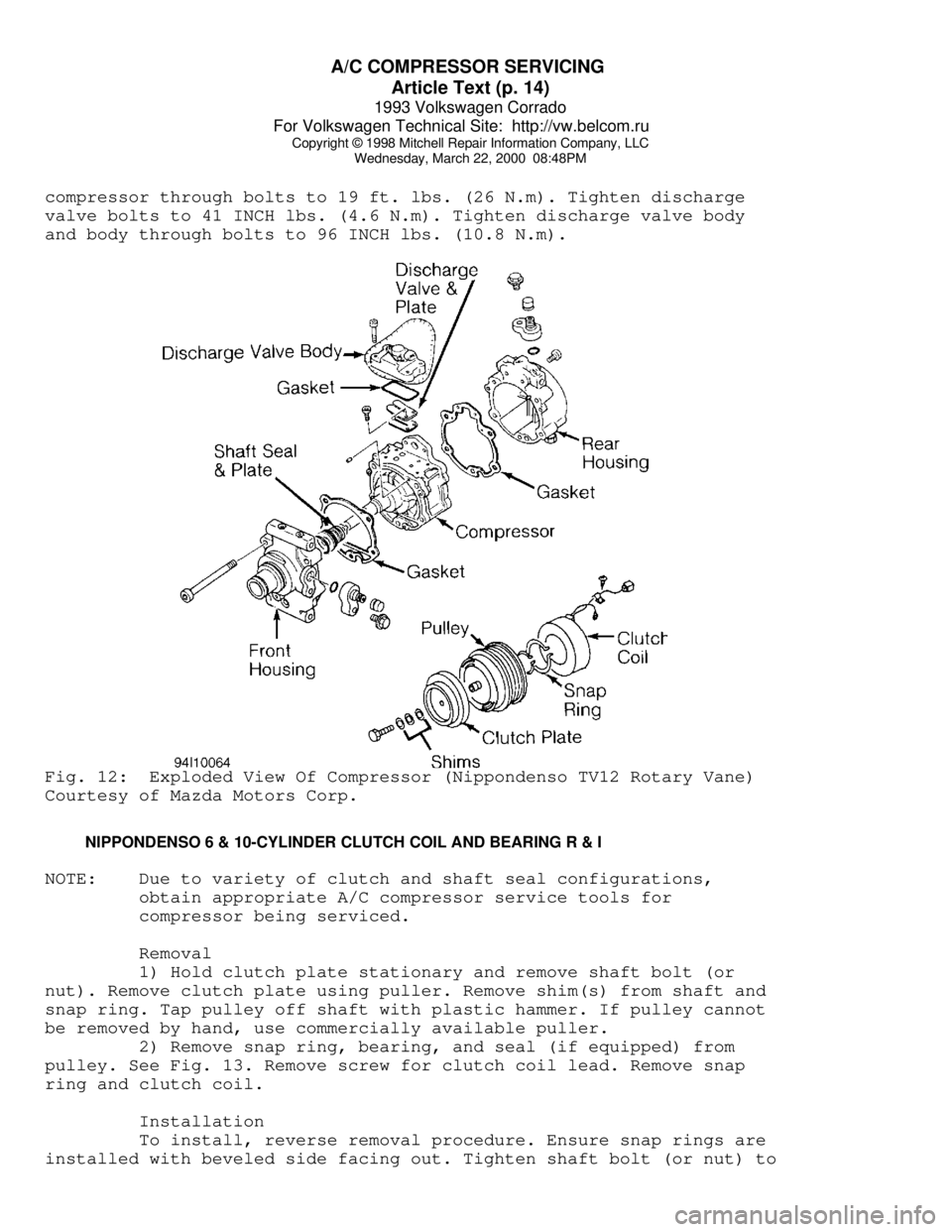
clutch disc and shims. See Fig. 12.
2) Remove pulley snap ring and tap pulley (with bearing) off
of compressor with plastic hammer. Remove screw for clutch coil lead.
Remove snap ring and clutch coil.
Installation
To install, reverse removal procedure. Ensure pulley-to-
clutch disc clearance is .016-.024" (.40-.60 mm). If clearance is
incorrect, add or remove shim(s) as necessary.
NIPPONDENSO TV12 DISCHARGE VALVE & SHAFT SEAL R & I
Removal
1) Drain and measure compressor oil in compressor. Remove
discharge valve body through bolts. Remove discharge valve body bolts
and body. Remove discharge valve plate and discharge valve.
2) Remove compressor through bolts and front and rear housing
(oil separator case). Remove pins and gaskets. Remove shaft seal from
shaft. Press shaft seal plate off of front housing (head cover).
Installation
To install components, reverse removal procedure. Tighten
Page 350 of 920
A/C COMPRESSOR SERVICING
Article Text (p. 14)
1993 Volkswagen Corrado
For Volkswagen Technical Site: http://vw.belcom.ru
Copyright © 1998 Mitchell Repair Information Company, LLC
Wednesday, March 22, 2000 08:48PM
compressor through bolts to 19 ft. lbs. (26 N.m). Tighten discharge
valve bolts to 41 INCH lbs. (4.6 N.m). Tighten discharge valve body
and body through bolts to 96 INCH lbs. (10.8 N.m).Fig. 12: Exploded View Of Compressor (Nippondenso TV12 Rotary Vane)
Courtesy of Mazda Motors Corp.
NIPPONDENSO 6 & 10-CYLINDER CLUTCH COIL AND BEARING R & I
NOTE: Due to variety of clutch and shaft seal configurations,
obtain appropriate A/C compressor service tools for
compressor being serviced.
Removal
1) Hold clutch plate stationary and remove shaft bolt (or
nut). Remove clutch plate using puller. Remove shim(s) from shaft and
snap ring. Tap pulley off shaft with plastic hammer. If pulley cannot
be removed by hand, use commercially available puller.
2) Remove snap ring, bearing, and seal (if equipped) from
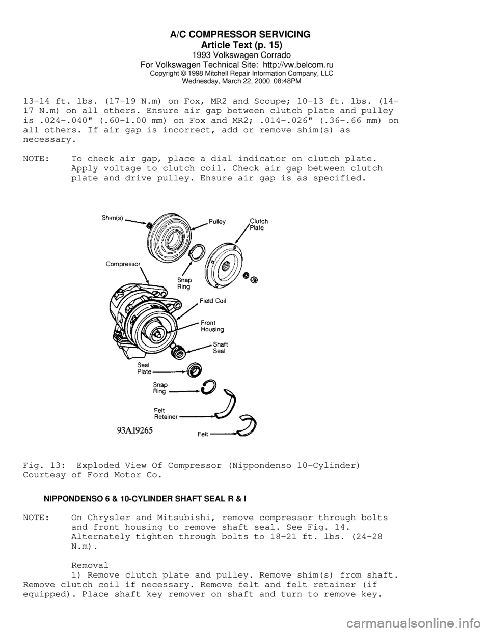
pulley. See Fig. 13. Remove screw for clutch coil lead. Remove snap
ring and clutch coil.
Installation
To install, reverse removal procedure. Ensure snap rings are
installed with beveled side facing out. Tighten shaft bolt (or nut) to
Page 351 of 920
A/C COMPRESSOR SERVICING
Article Text (p. 15)
1993 Volkswagen Corrado
For Volkswagen Technical Site: http://vw.belcom.ru
Copyright © 1998 Mitchell Repair Information Company, LLC
Wednesday, March 22, 2000 08:48PM
13-14 ft. lbs. (17-19 N.m) on Fox, MR2 and Scoupe; 10-13 ft. lbs. (14-
17 N.m) on all others. Ensure air gap between clutch plate and pulley
is .024-.040" (.60-1.00 mm) on Fox and MR2; .014-.026" (.36-.66 mm) on
all others. If air gap is incorrect, add or remove shim(s) as
necessary.
NOTE: To check air gap, place a dial indicator on clutch plate.
Apply voltage to clutch coil. Check air gap between clutch
plate and drive pulley. Ensure air gap is as specified.Fig. 13: Exploded View Of Compressor (Nippondenso 10-Cylinder)
Courtesy of Ford Motor Co.
NIPPONDENSO 6 & 10-CYLINDER SHAFT SEAL R & I
NOTE: On Chrysler and Mitsubishi, remove compressor through bolts
and front housing to remove shaft seal. See Fig. 14.
Alternately tighten through bolts to 18-21 ft. lbs. (24-28
N.m).
Removal
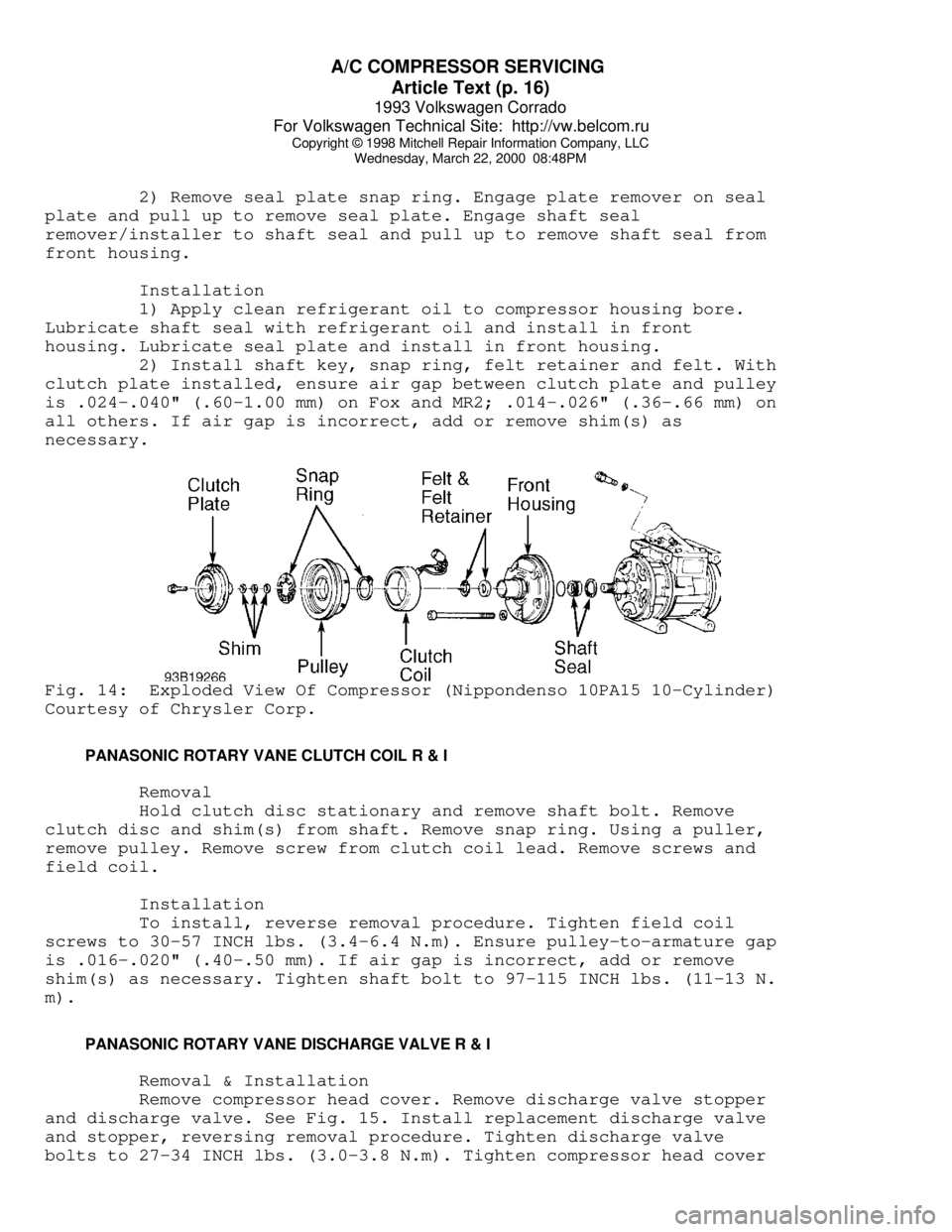
1) Remove clutch plate and pulley. Remove shim(s) from shaft.
Remove clutch coil if necessary. Remove felt and felt retainer (if
equipped). Place shaft key remover on shaft and turn to remove key.
Page 352 of 920
A/C COMPRESSOR SERVICING
Article Text (p. 16)
1993 Volkswagen Corrado
For Volkswagen Technical Site: http://vw.belcom.ru
Copyright © 1998 Mitchell Repair Information Company, LLC
Wednesday, March 22, 2000 08:48PM
2) Remove seal plate snap ring. Engage plate remover on seal
plate and pull up to remove seal plate. Engage shaft seal
remover/installer to shaft seal and pull up to remove shaft seal from
front housing.
Installation
1) Apply clean refrigerant oil to compressor housing bore.
Lubricate shaft seal with refrigerant oil and install in front
housing. Lubricate seal plate and install in front housing.
2) Install shaft key, snap ring, felt retainer and felt. With
clutch plate installed, ensure air gap between clutch plate and pulley
is .024-.040" (.60-1.00 mm) on Fox and MR2; .014-.026" (.36-.66 mm) on
all others. If air gap is incorrect, add or remove shim(s) as
necessary.Fig. 14: Exploded View Of Compressor (Nippondenso 10PA15 10-Cylinder)
Courtesy of Chrysler Corp.
PANASONIC ROTARY VANE CLUTCH COIL R & I
Removal
Hold clutch disc stationary and remove shaft bolt. Remove
clutch disc and shim(s) from shaft. Remove snap ring. Using a puller,
remove pulley. Remove screw from clutch coil lead. Remove screws and
field coil.
Installation
To install, reverse removal procedure. Tighten field coil
screws to 30-57 INCH lbs. (3.4-6.4 N.m). Ensure pulley-to-armature gap
is .016-.020" (.40-.50 mm). If air gap is incorrect, add or remove
shim(s) as necessary. Tighten shaft bolt to 97-115 INCH lbs. (11-13 N.
m).
PANASONIC ROTARY VANE DISCHARGE VALVE R & I
Removal & Installation
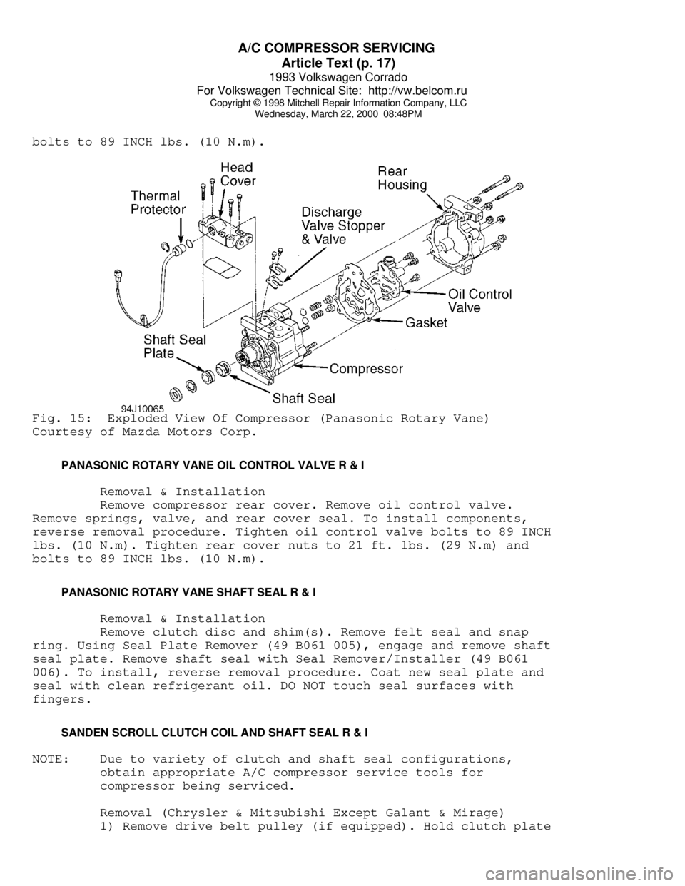
Remove compressor head cover. Remove discharge valve stopper
and discharge valve. See Fig. 15. Install replacement discharge valve
and stopper, reversing removal procedure. Tighten discharge valve
bolts to 27-34 INCH lbs. (3.0-3.8 N.m). Tighten compressor head cover
Page 353 of 920
A/C COMPRESSOR SERVICING
Article Text (p. 17)
1993 Volkswagen Corrado
For Volkswagen Technical Site: http://vw.belcom.ru
Copyright © 1998 Mitchell Repair Information Company, LLC
Wednesday, March 22, 2000 08:48PM
bolts to 89 INCH lbs. (10 N.m).Fig. 15: Exploded View Of Compressor (Panasonic Rotary Vane)
Courtesy of Mazda Motors Corp.
PANASONIC ROTARY VANE OIL CONTROL VALVE R & I
Removal & Installation
Remove compressor rear cover. Remove oil control valve.
Remove springs, valve, and rear cover seal. To install components,
reverse removal procedure. Tighten oil control valve bolts to 89 INCH
lbs. (10 N.m). Tighten rear cover nuts to 21 ft. lbs. (29 N.m) and
bolts to 89 INCH lbs. (10 N.m).
PANASONIC ROTARY VANE SHAFT SEAL R & I
Removal & Installation
Remove clutch disc and shim(s). Remove felt seal and snap
ring. Using Seal Plate Remover (49 B061 005), engage and remove shaft
seal plate. Remove shaft seal with Seal Remover/Installer (49 B061
006). To install, reverse removal procedure. Coat new seal plate and
seal with clean refrigerant oil. DO NOT touch seal surfaces with
fingers.
SANDEN SCROLL CLUTCH COIL AND SHAFT SEAL R & I
NOTE: Due to variety of clutch and shaft seal configurations,
obtain appropriate A/C compressor service tools for
compressor being serviced.
Removal (Chrysler & Mitsubishi Except Galant & Mirage)
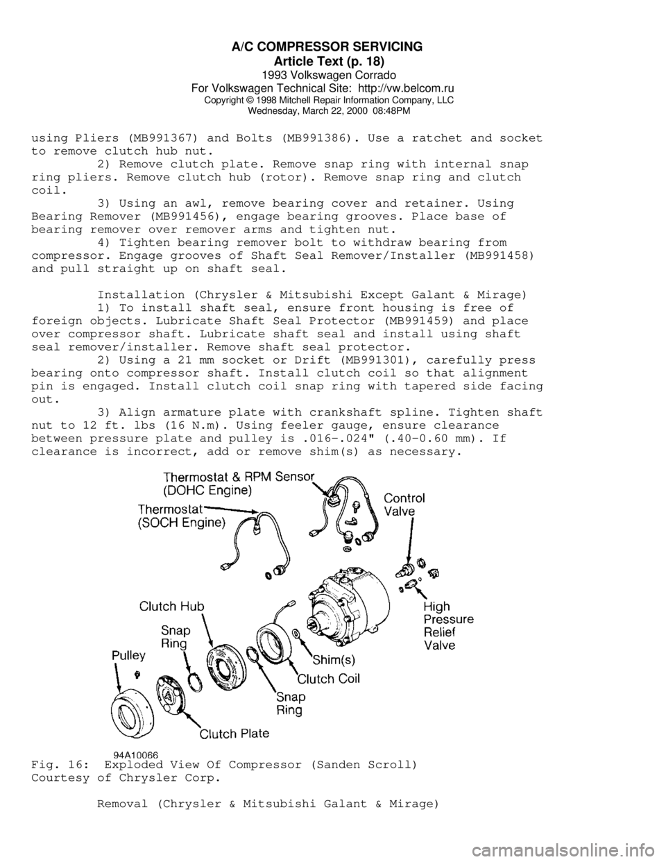
1) Remove drive belt pulley (if equipped). Hold clutch plate
Page 354 of 920
A/C COMPRESSOR SERVICING
Article Text (p. 18)
1993 Volkswagen Corrado
For Volkswagen Technical Site: http://vw.belcom.ru
Copyright © 1998 Mitchell Repair Information Company, LLC
Wednesday, March 22, 2000 08:48PM
using Pliers (MB991367) and Bolts (MB991386). Use a ratchet and socket
to remove clutch hub nut.
2) Remove clutch plate. Remove snap ring with internal snap
ring pliers. Remove clutch hub (rotor). Remove snap ring and clutch
coil.
3) Using an awl, remove bearing cover and retainer. Using
Bearing Remover (MB991456), engage bearing grooves. Place base of
bearing remover over remover arms and tighten nut.
4) Tighten bearing remover bolt to withdraw bearing from
compressor. Engage grooves of Shaft Seal Remover/Installer (MB991458)
and pull straight up on shaft seal.
Installation (Chrysler & Mitsubishi Except Galant & Mirage)
1) To install shaft seal, ensure front housing is free of
foreign objects. Lubricate Shaft Seal Protector (MB991459) and place
over compressor shaft. Lubricate shaft seal and install using shaft
seal remover/installer. Remove shaft seal protector.
2) Using a 21 mm socket or Drift (MB991301), carefully press
bearing onto compressor shaft. Install clutch coil so that alignment
pin is engaged. Install clutch coil snap ring with tapered side facing
out.
3) Align armature plate with crankshaft spline. Tighten shaft
nut to 12 ft. lbs (16 N.m). Using feeler gauge, ensure clearance
between pressure plate and pulley is .016-.024" (.40-0.60 mm). If
clearance is incorrect, add or remove shim(s) as necessary.Fig. 16: Exploded View Of Compressor (Sanden Scroll)
Courtesy of Chrysler Corp.
Removal (Chrysler & Mitsubishi Galant & Mirage)
Page 355 of 920
A/C COMPRESSOR SERVICING
Article Text (p. 19)
1993 Volkswagen Corrado
For Volkswagen Technical Site: http://vw.belcom.ru
Copyright © 1998 Mitchell Repair Information Company, LLC
Wednesday, March 22, 2000 08:48PM
1) Hold clutch plate by securing 2 box-end wrenches with two
6-mm bolts, 1" (25 mm) or longer. Holding bow-end wrenches, use a
ratchet and socket to remove clutch hub nut.
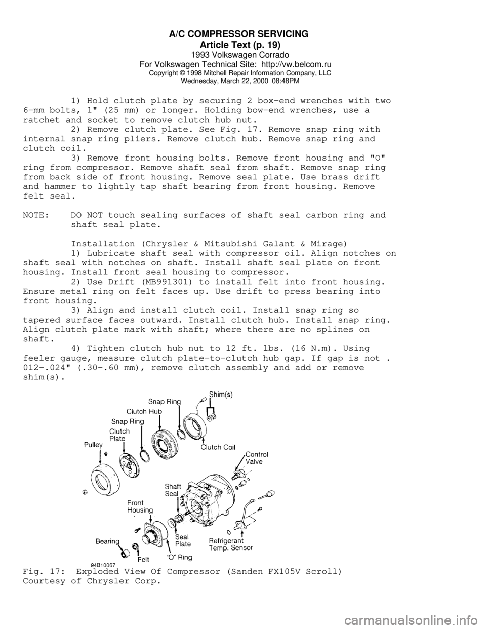
2) Remove clutch plate. See Fig. 17. Remove snap ring with
internal snap ring pliers. Remove clutch hub. Remove snap ring and
clutch coil.
3) Remove front housing bolts. Remove front housing and "O"
ring from compressor. Remove shaft seal from shaft. Remove snap ring
from back side of front housing. Remove seal plate. Use brass drift
and hammer to lightly tap shaft bearing from front housing. Remove
felt seal.
NOTE: DO NOT touch sealing surfaces of shaft seal carbon ring and
shaft seal plate.
Installation (Chrysler & Mitsubishi Galant & Mirage)
1) Lubricate shaft seal with compressor oil. Align notches on
shaft seal with notches on shaft. Install shaft seal plate on front
housing. Install front seal housing to compressor.
2) Use Drift (MB991301) to install felt into front housing.
Ensure metal ring on felt faces up. Use drift to press bearing into
front housing.
3) Align and install clutch coil. Install snap ring so
tapered surface faces outward. Install clutch hub. Install snap ring.
Align clutch plate mark with shaft; where there are no splines on
shaft.
4) Tighten clutch hub nut to 12 ft. lbs. (16 N.m). Using
feeler gauge, measure clutch plate-to-clutch hub gap. If gap is not .
012-.024" (.30-.60 mm), remove clutch assembly and add or remove
shim(s).Fig. 17: Exploded View Of Compressor (Sanden FX105V Scroll)
Courtesy of Chrysler Corp.