1993 VOLKSWAGEN CORRADO clutch
[x] Cancel search: clutchPage 135 of 920

* ENGINE SYSTEMS UNIFORM INSPECTION GUIDELINES *
Article Text (p. 38)
1993 Volkswagen Corrado
For Volkswagen Technical Site: http://vw.belcom.ru
Copyright © 1998 Mitchell Repair Information Company, LLC
Wednesday, March 22, 2000 08:41PM
Missing ³ Require replacement.
ÄÄÄÄÄÄÄÄÄÄÄÄÄÄÄÄÄÄÄÄÄÄÅÄÄÄÄÄÄÄÄÄÄÄÄÄÄÄÄÄÄÄÄÄÄÄÄÄÄÄÄÄÄÄÄÄÄÄÄÄÄÄÄÄÄÄÄÄÄÄDamaged
³ Suggest repair or replacement.
ÄÄÄÄÄÄÄÄÄÄÄÄÄÄÄÄÄÄÄÄÄÄÅÄÄÄÄÄÄÄÄÄÄÄÄÄÄÄÄÄÄÄÄÄÄÄÄÄÄÄÄÄÄÄÄÄÄÄÄÄÄÄÄÄÄÄÄÄÄÄInoperative
³ Require replacement.
ÄÄÄÄÄÄÄÄÄÄÄÄÄÄÄÄÄÄÄÄÄÄÅÄÄÄÄÄÄÄÄÄÄÄÄÄÄÄÄÄÄÄÄÄÄÄÄÄÄÄÄÄÄÄÄÄÄÄÄÄÄÄÄÄÄÄÄÄÄÄLeaking
³ Require replacement.
ÄÄÄÄÄÄÄÄÄÄÄÄÄÄÄÄÄÄÄÄÄÄÁÄÄÄÄÄÄÄÄÄÄÄÄÄÄÄÄÄÄÄÄÄÄÄÄÄÄÄÄÄÄÄÄÄÄÄÄÄÄÄÄÄÄÄÄÄÄÄ TRANSMISSION & CLUTCH RELATED INSPECTION INFORMATION
AUTOMATIC TRANSMISSION FILTER
ÄÄÄÄÄÄÄÄÄÄÄÄÄÄÄÄÄÄÄÄÄÄÂÄÄÄÄÄÄÄÄÄÄÄÄÄÄÄÄÄÄÄÄÄÄÄÄÄÄÄÄÄÄÄÄÄÄÄÄÄÄÄÄÄÄÄÄÄÄÄCondition
³ Procedure
ÄÄÄÄÄÄÄÄÄÄÄÄÄÄÄÄÄÄÄÄÄÄÅÄÄÄÄÄÄÄÄÄÄÄÄÄÄÄÄÄÄÄÄÄÄÄÄÄÄÄÄÄÄÄÄÄÄÄÄÄÄÄÄÄÄÄÄÄÄÄContaminated
³ Require replacement of fluid and filter.
ÄÄÄÄÄÄÄÄÄÄÄÄÄÄÄÄÄÄÄÄÄÄÅÄÄÄÄÄÄÄÄÄÄÄÄÄÄÄÄÄÄÄÄÄÄÄÄÄÄÄÄÄÄÄÄÄÄÄÄÄÄÄÄÄÄÄÄÄÄÄMaintenance intervals
³ Suggest replacement to comply with OEM
³ recommended service intervals.
ÄÄÄÄÄÄÄÄÄÄÄÄÄÄÄÄÄÄÄÄÄÄÁÄÄÄÄÄÄÄÄÄÄÄÄÄÄÄÄÄÄÄÄÄÄÄÄÄÄÄÄÄÄÄÄÄÄÄÄÄÄÄÄÄÄÄÄÄÄÄ TRANSMISSION FLUID
ÄÄÄÄÄÄÄÄÄÄÄÄÄÄÄÄÄÄÄÄÄÄÂÄÄÄÄÄÄÄÄÄÄÄÄÄÄÄÄÄÄÄÄÄÄÄÄÄÄÄÄÄÄÄÄÄÄÄÄÄÄÄÄÄÄÄÄÄÄÄCondition
³ Procedure
ÄÄÄÄÄÄÄÄÄÄÄÄÄÄÄÄÄÄÄÄÄÄÁÄÄÄÄÄÄÄÄÄÄÄÄÄÄÄÄÄÄÄÄÄÄÄÄÄÄÄÄÄÄÄÄÄÄÄÄÄÄÄÄÄÄÄÄÄÄÄSee * TRANSMISSION UNIFORM INSPECTION GUIDELINES *. (1)
ÄÄÄÄÄÄÄÄÄÄÄÄÄÄÄÄÄÄÄÄÄÄÄÄÄÄÄÄÄÄÄÄÄÄÄÄÄÄÄÄÄÄÄÄÄÄÄÄÄÄÄÄÄÄÄÄÄÄÄÄÄÄÄÄÄÄÄÄÄÄ(1) - TRANSMISSION UNIFORM INSPECTION GUIDELINES article is not
available at this time.
ÄÄÄÄÄÄÄÄÄÄÄÄÄÄÄÄÄÄÄÄÄÄÄÄÄÄÄÄÄÄÄÄÄÄÄÄÄÄÄÄÄÄÄÄÄÄÄÄÄÄÄÄÄÄÄÄÄÄÄÄÄÄÄÄÄÄÄÄÄÄ CLUTCH FLUID
ÄÄÄÄÄÄÄÄÄÄÄÄÄÄÄÄÄÄÄÄÄÄÂÄÄÄÄÄÄÄÄÄÄÄÄÄÄÄÄÄÄÄÄÄÄÄÄÄÄÄÄÄÄÄÄÄÄÄÄÄÄÄÄÄÄÄÄÄÄÄCondition
³ Procedure
ÄÄÄÄÄÄÄÄÄÄÄÄÄÄÄÄÄÄÄÄÄÄÁÄÄÄÄÄÄÄÄÄÄÄÄÄÄÄÄÄÄÄÄÄÄÄÄÄÄÄÄÄÄÄÄÄÄÄÄÄÄÄÄÄÄÄÄÄÄÄSee * TRANSMISSION UNIFORM INSPECTION GUIDELINES *. (1)
ÄÄÄÄÄÄÄÄÄÄÄÄÄÄÄÄÄÄÄÄÄÄÄÄÄÄÄÄÄÄÄÄÄÄÄÄÄÄÄÄÄÄÄÄÄÄÄÄÄÄÄÄÄÄÄÄÄÄÄÄÄÄÄÄÄÄÄÄÄÄ(1) - TRANSMISSION UNIFORM INSPECTION GUIDELINES article is not
available at this time.
ÄÄÄÄÄÄÄÄÄÄÄÄÄÄÄÄÄÄÄÄÄÄÄÄÄÄÄÄÄÄÄÄÄÄÄÄÄÄÄÄÄÄÄÄÄÄÄÄÄÄÄÄÄÄÄÄÄÄÄÄÄÄÄÄÄÄÄÄÄÄEND OF ARTICLE
Page 289 of 920
* SYMPTOM CHECK LIST *
Article Text (p. 12)
1993 Volkswagen Corrado
For Volkswagen Technical Site: http://vw.belcom.ru
Copyright © 1998 Mitchell Repair Information Company, LLC
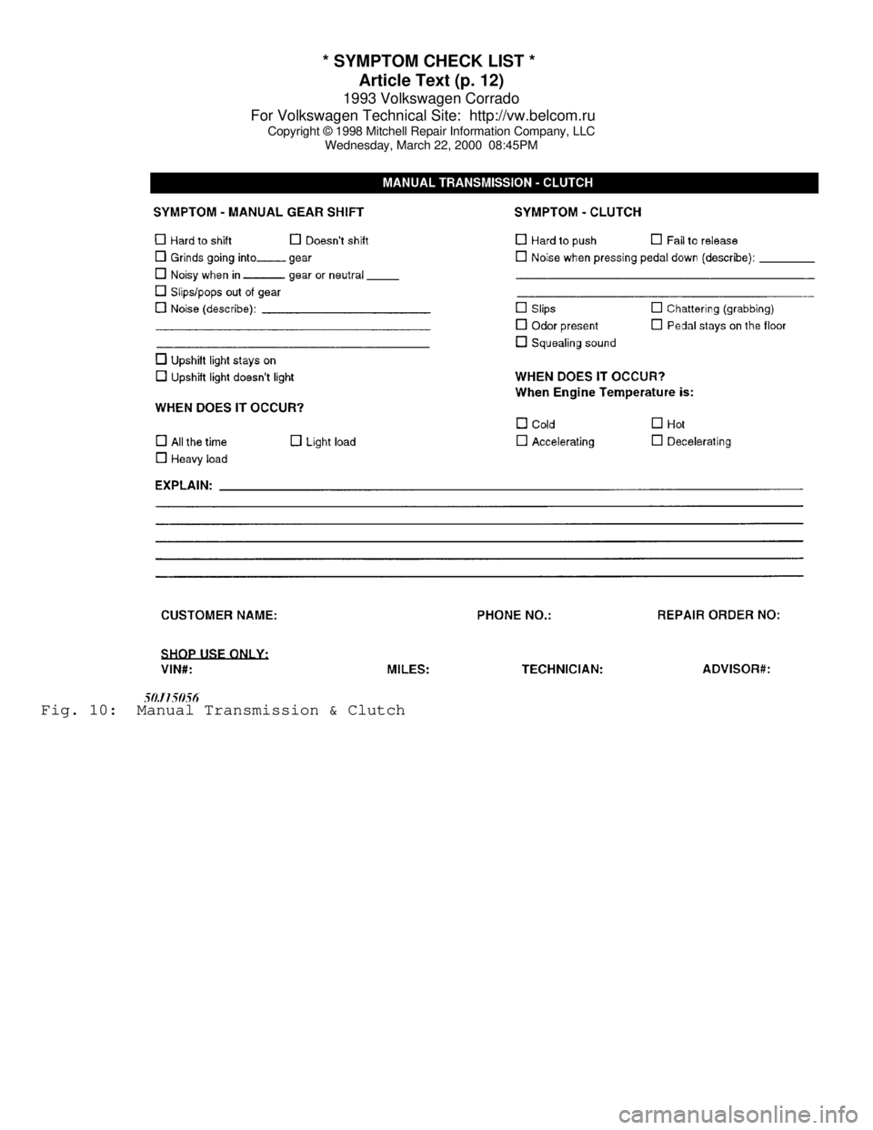
Wednesday, March 22, 2000 08:45PMFig. 10: Manual Transmission & Clutch
Page 293 of 920
2.8L IN-LINE V6 (VR6)
Article Text (p. 2)
1993 Volkswagen Corrado
For Volkswagen Technical Site: http://vw.belcom.ru
Copyright © 1998 Mitchell Repair Information Company, LLC
Wednesday, March 22, 2000 08:47PM
ADJUSTMENTS
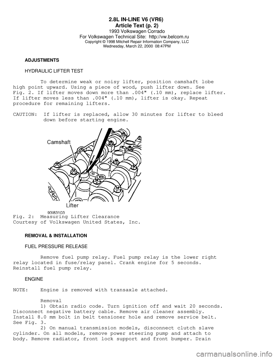
HYDRAULIC LIFTER TEST
To determine weak or noisy lifter, position camshaft lobe
high point upward. Using a piece of wood, push lifter down. See
Fig. 2. If lifter moves down more than .004" (.10 mm), replace lifter.
If lifter moves less than .004" (.10 mm), lifter is okay. Repeat
procedure for remaining lifters.
CAUTION: If lifter is replaced, allow 30 minutes for lifter to bleed
down before starting engine.Fig. 2: Measuring Lifter Clearance
Courtesy of Volkswagen United States, Inc.
REMOVAL & INSTALLATION
FUEL PRESSURE RELEASE
Remove fuel pump relay. Fuel pump relay is the lower right
relay located in fuse/relay panel. Crank engine for 5 seconds.
Reinstall fuel pump relay.
ENGINE
NOTE: Engine is removed with transaxle attached.
Removal
1) Obtain radio code. Turn ignition off and wait 20 seconds.
Disconnect negative battery cable. Remove air cleaner assembly.
Install 8.0 mm bolt in belt tensioner hole and remove service belt.
See Fig. 3.
2) On manual transmission models, disconnect clutch slave
cylinder. On all models, remove power steering pump and attach to
body. Remove radiator, front lock support and front bumper. Drain
Page 297 of 920
2.8L IN-LINE V6 (VR6)
Article Text (p. 6)
1993 Volkswagen Corrado
For Volkswagen Technical Site: http://vw.belcom.ru
Copyright © 1998 Mitchell Repair Information Company, LLC
Wednesday, March 22, 2000 08:47PM
CRANKSHAFT OIL SEAL
Removal
Install 8.0 mm bolt in belt tensioner hole and remove
accessory drive belt. See Fig. 3. Remove vibration damper. Loosen
inner section of Oil Seal Extractor (3203) about 3 turns (4 mm) and
lock in position with knurled screw. Turn inner section of oil seal
extractor until seal is removed.
Installation
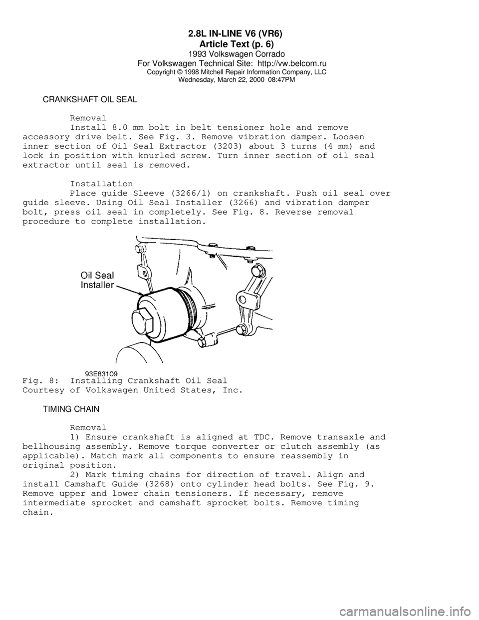
Place guide Sleeve (3266/1) on crankshaft. Push oil seal over
guide sleeve. Using Oil Seal Installer (3266) and vibration damper
bolt, press oil seal in completely. See Fig. 8. Reverse removal
procedure to complete installation.Fig. 8: Installing Crankshaft Oil Seal
Courtesy of Volkswagen United States, Inc.
TIMING CHAIN
Removal
1) Ensure crankshaft is aligned at TDC. Remove transaxle and
bellhousing assembly. Remove torque converter or clutch assembly (as
applicable). Match mark all components to ensure reassembly in
original position.
2) Mark timing chains for direction of travel. Align and
install Camshaft Guide (3268) onto cylinder head bolts. See Fig. 9.
Remove upper and lower chain tensioners. If necessary, remove
intermediate sprocket and camshaft sprocket bolts. Remove timing
chain.
Page 307 of 920

2.8L IN-LINE V6 (VR6)
Article Text (p. 16)
1993 Volkswagen Corrado
For Volkswagen Technical Site: http://vw.belcom.ru
Copyright © 1998 Mitchell Repair Information Company, LLC
Wednesday, March 22, 2000 08:47PM
TORQUE SPECIFICATIONS
TORQUE SPECIFICATIONS TABLEÄÄÄÄÄÄÄÄÄÄÄÄÄÄÄÄÄÄÄÄÄÄÄÄÄÄÄÄÄÄÄÄÄÄÄÄÄÄÄÄÄÄÄÄÄÄÄÄÄÄÄÄÄÄÄÄÄÄÄÄApplication Ft. Lbs. (N.m)
A/C Bracket-To-Engine Bolt ....................... 22 (30)
Axle Shaft-To-Transaxle Drive Flange Bolt ........ 33 (45)
Camshaft Bearing Cap Bolt ........................ 15 (20)
Camshaft Sprocket Bolt .......................... 74 (100)
Clutch Cover Bolt ................................ 15 (20)
Connecting Rod Bolt ................... 22 (30) + 1/4 Turn
Crankshaft Main Bearing Cap Bolt ...... 22 (30) + 1/2 Turn
Cylinder Head Bolt (1)
Step 1 ......................................... 30 (40)
Step 2 ......................................... 44 (60)
Step 3 ....................... Additional 1/4 (90
ø) Turn
Step 4 ....................... Additional 1/4 (90
ø) Turn
Engine Bracket (Front) ........................... 44 (60)
Engine Bracket (To Body) ......................... 33 (45)
Engine-To-Transaxle 10-mm Bolt ................... 44 (60)
Engine-To-Transaxle 12-mm Bolt ................... 55 (80)
Exhaust Manifold-To-Cylinder Head Bolt & Nut ..... 18 (25)
Exhaust Pipe-To-Catalytic Converter Bolt ......... 18 (25)
Exhaust Pipe-To-Manifold Nut ..................... 30 (40)
Flywheel-To-Crankshaft Bolt ........... 44 (60) + 1/4 Turn
Intake Manifold .................................. 18 (25)
Intermediate Shaft Sprocket Bolt ................ 74 (100)
Oil Pan Bolt ..................................... 15 (20)
Oil Pan Drain Plug ............................... 37 (50)
Oil Pressure Switch .............................. 18 (25)
Oil Pump Cover Long Bolt ............................. (2)
Oil Pump Cover Short Bolt ........................ 18 (25)
Power Steering Pump Bracket Bolt ................. 18 (25)
Pressure Plate Bolt .............................. 15 (20)
Starter Mount Bolt ............................... 18 (25)
Timing Belt Tensioner Nut ........................ 15 (20)
Torque Converter-To-Carrier Plate Bolt ........... 22 (30)
Vibration Damper Bolt .......................... 332 (450)
Water Pump Pulley Bolt ........................... 15 (20)
Water Pump Housing-To-Engine Bolt ................ 15 (20)
INCH Lbs. (N.m)
Fuel Rail Bolt (Lower) ............................ 89 (10)
Timing Belt Idler Bolt ........................... 89 (10)
Valve Cover Retaining Nut ........................ 89 (10)
Water Pump-To-Housing ........................... 115 (13)
(1) - Never reuse cylinder head bolt(s) when servicing.
(2) - Tighten bolt to 89 INCH lbs. (10 N.m).
ÄÄÄÄÄÄÄÄÄÄÄÄÄÄÄÄÄÄÄÄÄÄÄÄÄÄÄÄÄÄÄÄÄÄÄÄÄÄÄÄÄÄÄÄÄÄÄÄÄÄÄÄÄÄÄÄÄÄÄÄ
Page 337 of 920
A/C COMPRESSOR SERVICING
Article Text
1993 Volkswagen Corrado
For Volkswagen Technical Site: http://vw.belcom.ru
Copyright © 1998 Mitchell Repair Information Company, LLC
Wednesday, March 22, 2000 08:48PM
ARTICLE BEGINNING
1993 AIR CONDITIONING & HEAT
Compressor Servicing
READ THIS FIRST
NOTE: The purpose of this article is to provide GENERAL servicing
overview. For more specific information, refer to the AUTO
A/C-HEAT SYSTEM, MANUAL A/C-HEAT SYSTEM, or HEATER SYSTEM
articles in this section.
NOTE: Due to variety of clutch and shaft seal configurations,
obtain appropriate A/C compressor service tools for
compressor being serviced.
ATSUGI ROTARY VANE CLUTCH COIL R & I
Removal
When replacing compressor clutch, be careful not to scratch
shaft or bend pulley. When removing center bolt, hold clutch disc with
Clutch Holder (KV99231010). Using Hub Puller (KV998VR001), remove
clutch disc. When removing pulley, remove lock nut with Hub Socket
(KV99235160).
Installation
1) Tighten center bolt to 81-104 INCH lbs. (9.1-11.8 N.m).
Tighten lock nut to 21-29 ft. lbs. (29-39 N.m). Using feeler gauge,
ensure clearance between clutch disc and pulley is .012-.024" (.30-.60
mm).
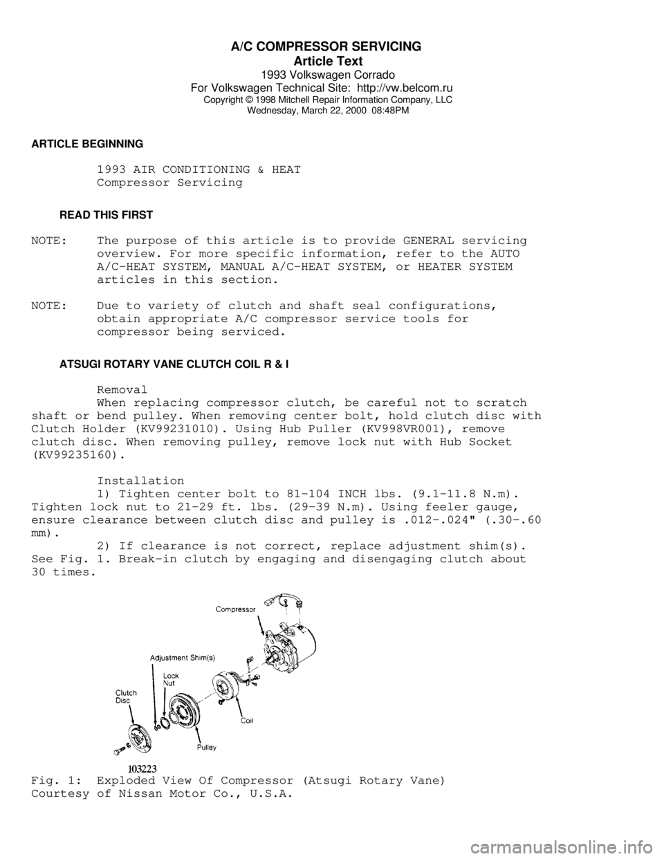
2) If clearance is not correct, replace adjustment shim(s).
See Fig. 1. Break-in clutch by engaging and disengaging clutch about
30 times.Fig. 1: Exploded View Of Compressor (Atsugi Rotary Vane)
Courtesy of Nissan Motor Co., U.S.A.
Page 338 of 920
A/C COMPRESSOR SERVICING
Article Text (p. 2)
1993 Volkswagen Corrado
For Volkswagen Technical Site: http://vw.belcom.ru
Copyright © 1998 Mitchell Repair Information Company, LLC
Wednesday, March 22, 2000 08:48PM
BOSCH 6-CYLINDER CLUTCH COIL R & I
Removal
1) Hold clutch plate and remove shaft nut. Using Clutch Plate
Remover (64 5 00), remove clutch plate. Using snap ring pliers, remove
circlip and remove pulley assembly.
2) If pulley bearing is being replaced, remove circlip at
rear of pulley. Press bearing and spacer from pulley. Press in new
bearing with spacer and replace circlip.
Installation
1) Clean all surfaces. Install pulley assembly on compressor
and install circlip. Ensure clutch plate shim is in place on shaft.
Install clutch plate and nut. Tighten nut to 13-15 ft. lbs. (18-20 N.
m).
2) Using a feeler gauge, check clutch plate-to-pulley
clearance. Clearance should be .028-.051" (.7-1.3 mm). If clearance is
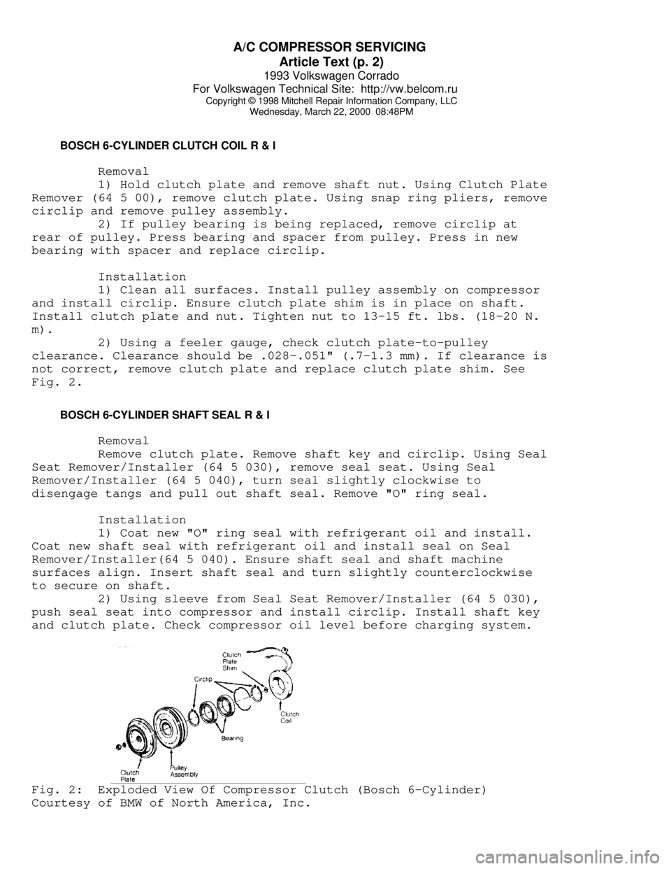
not correct, remove clutch plate and replace clutch plate shim. See
Fig. 2.
BOSCH 6-CYLINDER SHAFT SEAL R & I
Removal
Remove clutch plate. Remove shaft key and circlip. Using Seal
Seat Remover/Installer (64 5 030), remove seal seat. Using Seal
Remover/Installer (64 5 040), turn seal slightly clockwise to
disengage tangs and pull out shaft seal. Remove "O" ring seal.
Installation
1) Coat new "O" ring seal with refrigerant oil and install.
Coat new shaft seal with refrigerant oil and install seal on Seal
Remover/Installer(64 5 040). Ensure shaft seal and shaft machine
surfaces align. Insert shaft seal and turn slightly counterclockwise
to secure on shaft.
2) Using sleeve from Seal Seat Remover/Installer (64 5 030),
push seal seat into compressor and install circlip. Install shaft key
and clutch plate. Check compressor oil level before charging system.Fig. 2: Exploded View Of Compressor Clutch (Bosch 6-Cylinder)
Courtesy of BMW of North America, Inc.
Page 339 of 920
A/C COMPRESSOR SERVICING
Article Text (p. 3)
1993 Volkswagen Corrado
For Volkswagen Technical Site: http://vw.belcom.ru
Copyright © 1998 Mitchell Repair Information Company, LLC
Wednesday, March 22, 2000 08:48PM
CALSONIC V5 & V6 CLUTCH COIL R & I
NOTE: Calsonic V6 compressor servicing procedure is not available
from manufacturer.
Removal
1) Remove shaft nut while holding clutch plate with Clutch
Disc Wrench (J-39072). Install clutch disc Puller Set (J-39073-4, J-
33013-1, J-33013-3) and remove clutch plate.
2) Remove snap ring. Use a universal gear puller to remove
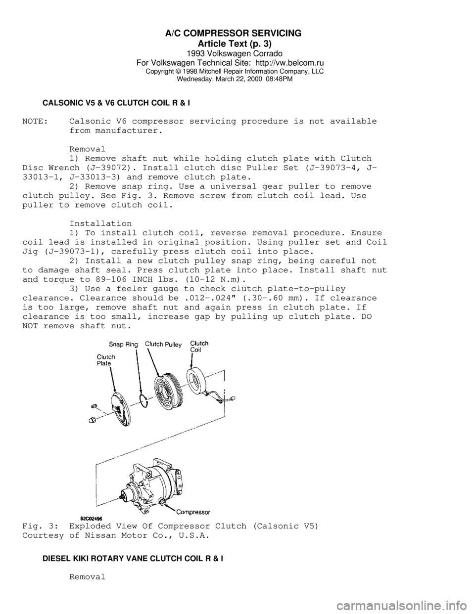
clutch pulley. See Fig. 3. Remove screw from clutch coil lead. Use
puller to remove clutch coil.
Installation
1) To install clutch coil, reverse removal procedure. Ensure
coil lead is installed in original position. Using puller set and Coil
Jig (J-39073-1), carefully press clutch coil into place.
2) Install a new clutch pulley snap ring, being careful not
to damage shaft seal. Press clutch plate into place. Install shaft nut
and torque to 89-106 INCH lbs. (10-12 N.m).
3) Use a feeler gauge to check clutch plate-to-pulley
clearance. Clearance should be .012-.024" (.30-.60 mm). If clearance
is too large, remove shaft nut and again press in clutch plate. If
clearance is too small, increase gap by pulling up clutch plate. DO
NOT remove shaft nut.Fig. 3: Exploded View Of Compressor Clutch (Calsonic V5)
Courtesy of Nissan Motor Co., U.S.A.
DIESEL KIKI ROTARY VANE CLUTCH COIL R & I
Removal