1993 VOLKSWAGEN CORRADO clutch
[x] Cancel search: clutchPage 356 of 920

A/C COMPRESSOR SERVICING
Article Text (p. 20)
1993 Volkswagen Corrado
For Volkswagen Technical Site: http://vw.belcom.ru
Copyright © 1998 Mitchell Repair Information Company, LLC
Wednesday, March 22, 2000 08:48PM
Removal & Installation (Honda & Hyundai)
1) Remove shaft nut while holding clutch plate with Armature
Holder (J-37872). Using Puller (07935-8050003), remove pressure plate
and shim(s). See Fig. 16. Remove snap ring.
2) Place Seal Driver (07945-4150200) in center of pulley.
Engage universal puller to outer diameter of pulley. DO NOT engage
puller on belt area. Hold puller in place and tighten screw to remove
pulley. Remove screw for clutch coil lead. Remove snap ring and clutch
coil.
3) To install clutch coil, reverse removal procedure. Align
lug on clutch coil with hole in compressor. Install snap rings with
chamfered side facing out. Tighten shaft nut to 12-14 ft. lbs. (16-19
N.m). Using feeler gauge, ensure clearance between pressure plate and
pulley is .014-.026" (.35-.65 mm). If clearance is incorrect, add or
remove shim(s) as necessary.
NOTE: Shaft seal removal and installation procedures not available
from Honda or Hyundai.
SANDEN 5-CYLINDER CLUTCH COIL R & I
Removal
1) Hold clutch plate, using Holder (0000-41-0809-01), and
remove shaft nut. Remove clutch plate using Puller (0000-41-0809-02).
Remove shaft key and shim(s). Remove external front housing snap ring
and internal bearing snap ring (if used).
2) Install Clutch Pilot (0000-41-0810-77), Pulley/Clutch
Remover (0000-41-0810-76), and Puller (0000-41-0804-51/57) to remove
pulley assembly. Remove snap ring and drive bearing out of pulley.
Remove screw for clutch coil lead. Remove snap ring and clutch coil.
Installation
1) Install new bearing, ensuring Bearing Installer (000-41-
0804-43) contacts outer race of bearing. Install snap ring and ensure
bearing turns freely.
2) Install clutch coil, ensuring lug on coil aligns with hole
in front housing. Support compressor on rear mounting ears. Align
rotor on front housing hub. Use bearing installer and Driver (0000-41-
0810-59) to install pulley. With pulley seated, install snap ring(s).
Install shim(s) and shaft key.
3) Place clutch plate over shaft and, using Shaft Protector
(0000-41-0809-10), tap clutch plate into place. Install and tighten
shaft nut to 25-32 ft. lbs. (34-44 N.m). Using feeler gauge, ensure
clearance between clutch plate and pulley is .016-.032" (.40-.80 mm).
If clearance is incorrect, add or remove shim(s) as necessary.
SANDEN 5-CYLINDER CYLINDER HEAD & VALVE PLATE R & I
Removal & Installation
Remove compressor cylinder head (rear cover) bolts. Carefully
pry cylinder head of compressor. Remove reed valve plate and gasket.
To install components, reverse removal procedure. Tighten compressor
Page 357 of 920

A/C COMPRESSOR SERVICING
Article Text (p. 21)
1993 Volkswagen Corrado
For Volkswagen Technical Site: http://vw.belcom.ru
Copyright © 1998 Mitchell Repair Information Company, LLC
Wednesday, March 22, 2000 08:48PM
cylinder head bolts, in a crisscross pattern, to 21-29 ft. lbs. (29-39
N.m).
SANDEN 5-CYLINDER SHAFT SEAL R & I
Removal
Remove shaft nut and clutch plate. Remove shaft key and
shim(s). Carefully remove felt ring. Remove shaft seal seat snap ring.
Using Seal Seat Remover/Installer (0000-41-0810-73), carefully remove
seal seat. Using Shaft Seal Remover/Installer (0000-41-0812-11),
carefully remove shaft seal.
Installation
1) Install Seal Protector (0000-41-0812-13) over shaft. Place
new seal on remover/installer. DO NOT touch carbon sealing surface
with fingers. Dip seal in refrigerant oil and install. Remove seal
installer by turning counterclockwise.
2) Coat seal seat with refrigerant oil. Install seal seat
using remover/installer. Install seal seat snap ring (with flat side
down). Install shim(s), felt ring and shaft key. Install shaft nut and
clutch plate. Ensure clearance between clutch plate and pulley is .
016-.032" (.40-.80 mm). If clearance is incorrect, add or remove
shim(s) as necessary.
SANDEN 7-CYLINDER CLUTCH COIL AND BEARING R & I
NOTE: Due to variety of clutch and shaft seal configurations,
obtain appropriate A/C compressor service tools for
compressor being serviced.
Removal
1) Install two 6-mm bolts, 1" (25 mm) or longer, in clutch
plate holes. Using 2 box-end wrenches to hold bolts and to prevent
clutch plate from turning, remove shaft nut.
2) Remove clutch plate using Clutch Plate Puller (09977-
21100). Remove clutch shim(s) and bearing dust cover. Remove external
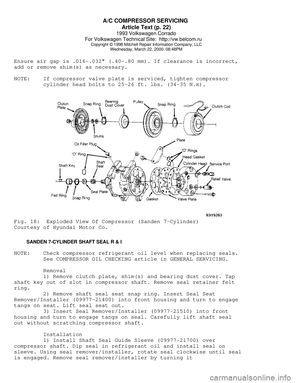
front housing snap ring. See Fig. 18.
3) Remove pulley using universal puller. Detach clutch coil
lead from compressor housing. Remove clutch coil snap ring and clutch
coil. If necessary, remove snap ring and bearing.
Installation
1) Align clutch coil lug with hole in compressor housing, and
install clutch coil. Install clutch coil snap ring. Install drive
pulley using Drive Pulley Installer (09977-21811).
2) Install external bearing snap ring. Using Seal Installer
(09977-21800), install bearing dust cover. After dust cover
installation, ensure there is no contact between cover and front
housing.
3) Install clutch shim(s) and clutch plate. Tighten shaft nut
to 13-14 ft. lbs. (17-19 N.m). Using a dial indicator, check air gap
between clutch plate and drive pulley. Apply voltage to clutch coil.
Page 358 of 920

A/C COMPRESSOR SERVICING
Article Text (p. 22)
1993 Volkswagen Corrado
For Volkswagen Technical Site: http://vw.belcom.ru
Copyright © 1998 Mitchell Repair Information Company, LLC
Wednesday, March 22, 2000 08:48PM
Ensure air gap is .016-.032" (.40-.80 mm). If clearance is incorrect,
add or remove shim(s) as necessary.
NOTE: If compressor valve plate is serviced, tighten compressor
cylinder head bolts to 25-26 ft. lbs. (34-35 N.m).Fig. 18: Exploded View Of Compressor (Sanden 7-Cylinder)
Courtesy of Hyundai Motor Co.
SANDEN 7-CYLINDER SHAFT SEAL R & I
NOTE: Check compressor refrigerant oil level when replacing seals.
See COMPRESSOR OIL CHECKING article in GENERAL SERVICING.
Removal
1) Remove clutch plate, shim(s) and bearing dust cover. Tap
shaft key out of slot in compressor shaft. Remove seal retainer felt
ring.
2) Remove shaft seal seat snap ring. Insert Seal Seat
Remover/Installer (09977-21400) into front housing and turn to engage
tangs on seat. Lift seal seat out.
3) Insert Seal Remover/Installer (09977-21510) into front
housing and turn to engage tangs on seal. Carefully lift shaft seal
out without scratching compressor shaft.
Installation
1) Install Shaft Seal Guide Sleeve (09977-21700) over
compressor shaft. Dip seal in refrigerant oil and install seal on
sleeve. Using seal remover/installer, rotate seal clockwise until seal
is engaged. Remove seal remover/installer by turning it
Page 359 of 920

A/C COMPRESSOR SERVICING
Article Text (p. 23)
1993 Volkswagen Corrado
For Volkswagen Technical Site: http://vw.belcom.ru
Copyright © 1998 Mitchell Repair Information Company, LLC
Wednesday, March 22, 2000 08:48PM
counterclockwise.
2) Coat seal seat with refrigerant oil and install seal with
seal seat remover/installer. Remove shaft seal guide sleeve. Install
snap ring with beveled edge facing out. Install seal retainer felt
ring using seal seat remover/installer.
3) Install shaft key and clutch plate. Tighten shaft nut to
13-14 ft. lbs. (17-19 N.m). Using a dial indicator, check air gap
between clutch plate and drive pulley. Apply voltage to clutch coil.
Ensure air gap is .016-.032" (.40-.80 mm). If clearance is incorrect,
add or remove shim(s) as necessary.
SEIKO-SEIKI ROTARY VANE
NOTE: Volvo Seiko-Seiki compressor servicing procedure is not
available from manufacturer.
ZEXEL ROTARY VANE CLUTCH COIL AND BEARING R & I
Removal
1) Hold clutch disc using Clutch Disc Wrench (KV99231260) and
remove center bolt. Using Clutch Disc Puller (KV99232340), remove
drive plate and adjustment shim(s).
2) Remove snap ring. Remove pulley using Pilot (J-39023) and
universal puller. Remove clutch coil. If necessary, remove snap ring
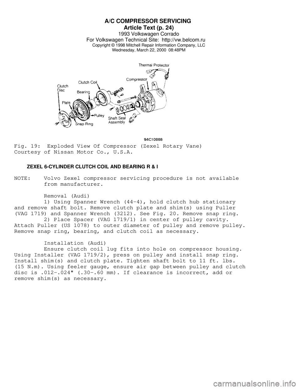
and bearing. See Fig. 19.
Installation
1) Ensure coil lead is installed in original position.
Install and tighten coil screws. Press pulley onto compressor using
Pulley Installer (J-33940). Install snap ring and adjustment shim(s).
2) Install clutch disc and tighten center bolt to 11-13 ft.
lbs. (15-18 N.m). Using feeler gauge, ensure clearance between clutch
disc and pulley is .012-.024" (.30-.60 mm). If clearance is incorrect,
add or remove shim(s) as necessary. Break-in clutch by engaging and
disengaging clutch 30 times.
NOTE: Shaft seal assembly servicing procedure is not available
from manufacturer. Use exploded view as a guide. See
Fig. 19. Tighten thermal protector, if removed, to
11-13 ft.lbs. (15-18 N.m).
Page 360 of 920

A/C COMPRESSOR SERVICING
Article Text (p. 24)
1993 Volkswagen Corrado
For Volkswagen Technical Site: http://vw.belcom.ru
Copyright © 1998 Mitchell Repair Information Company, LLC
Wednesday, March 22, 2000 08:48PMFig. 19: Exploded View Of Compressor (Zexel Rotary Vane)
Courtesy of Nissan Motor Co., U.S.A.
ZEXEL 6-CYLINDER CLUTCH COIL AND BEARING R & I
NOTE: Volvo Zexel compressor servicing procedure is not available
from manufacturer.
Removal (Audi)
1) Using Spanner Wrench (44-4), hold clutch hub stationary
and remove shaft bolt. Remove clutch plate and shim(s) using Puller
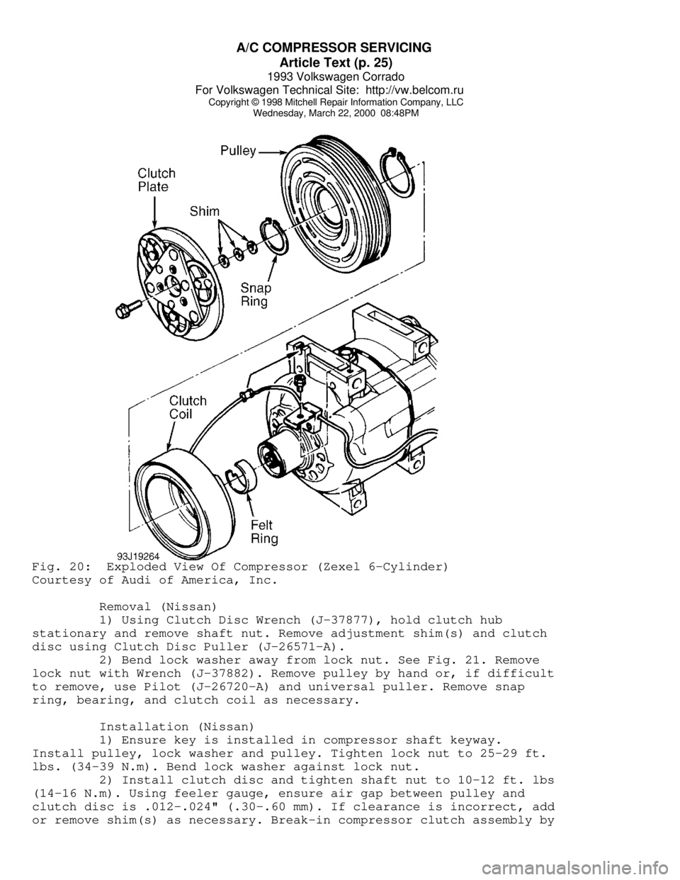
(VAG 1719) and Spanner Wrench (3212). See Fig. 20. Remove snap ring.
2) Place Spacer (VAG 1719/1) in center of pulley cavity.
Attach Puller (US 1078) to outer diameter of pulley and remove pulley.
Remove snap ring, bearing, and clutch coil as necessary.
Installation (Audi)
Ensure clutch coil lug fits into hole on compressor housing.
Using Installer (VAG 1719/2), press on pulley and install snap ring.
Install shim(s) and clutch plate. Tighten shaft bolt to 11 ft. lbs.
(15 N.m). Using feeler gauge, ensure air gap between pulley and clutch
disc is .012-.024" (.30-.60 mm). If clearance is incorrect, add or
remove shim(s) as necessary.
Page 361 of 920

A/C COMPRESSOR SERVICING
Article Text (p. 25)
1993 Volkswagen Corrado
For Volkswagen Technical Site: http://vw.belcom.ru
Copyright © 1998 Mitchell Repair Information Company, LLC
Wednesday, March 22, 2000 08:48PMFig. 20: Exploded View Of Compressor (Zexel 6-Cylinder)
Courtesy of Audi of America, Inc.
Removal (Nissan)
1) Using Clutch Disc Wrench (J-37877), hold clutch hub
stationary and remove shaft nut. Remove adjustment shim(s) and clutch
disc using Clutch Disc Puller (J-26571-A).
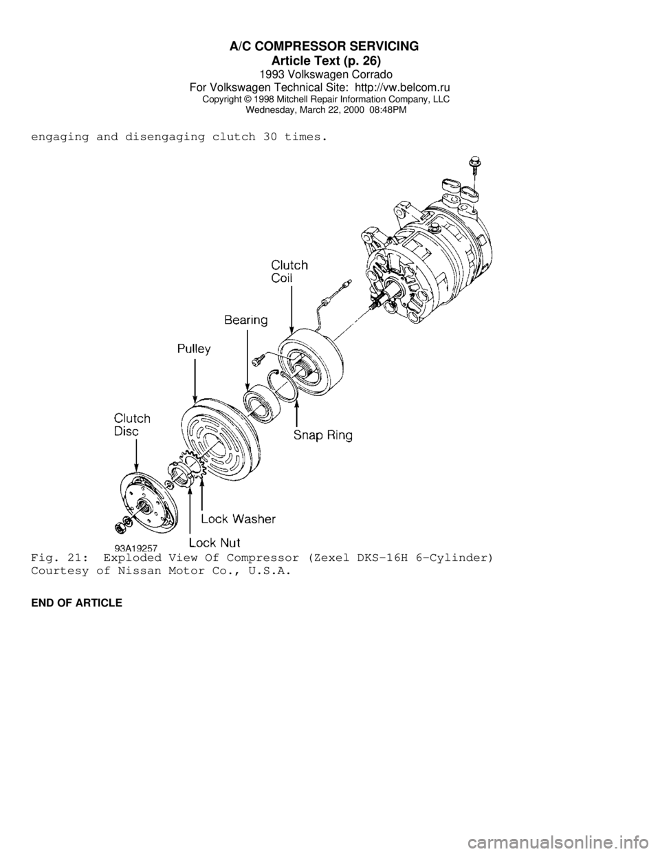
2) Bend lock washer away from lock nut. See Fig. 21. Remove
lock nut with Wrench (J-37882). Remove pulley by hand or, if difficult
to remove, use Pilot (J-26720-A) and universal puller. Remove snap
ring, bearing, and clutch coil as necessary.
Installation (Nissan)
1) Ensure key is installed in compressor shaft keyway.
Install pulley, lock washer and pulley. Tighten lock nut to 25-29 ft.
lbs. (34-39 N.m). Bend lock washer against lock nut.
2) Install clutch disc and tighten shaft nut to 10-12 ft. lbs
(14-16 N.m). Using feeler gauge, ensure air gap between pulley and
clutch disc is .012-.024" (.30-.60 mm). If clearance is incorrect, add
or remove shim(s) as necessary. Break-in compressor clutch assembly by
Page 362 of 920

A/C COMPRESSOR SERVICING
Article Text (p. 26)
1993 Volkswagen Corrado
For Volkswagen Technical Site: http://vw.belcom.ru
Copyright © 1998 Mitchell Repair Information Company, LLC
Wednesday, March 22, 2000 08:48PM
engaging and disengaging clutch 30 times.Fig. 21: Exploded View Of Compressor (Zexel DKS-16H 6-Cylinder)
Courtesy of Nissan Motor Co., U.S.A.
END OF ARTICLE
Page 366 of 920

A/C SYSTEM GENERAL DIAGNOSTIC PROCEDURES
Article Text (p. 4)
1993 Volkswagen Corrado
For Volkswagen Technical Site: http://vw.belcom.ru
Copyright © 1998 Mitchell Repair Information Company, LLC
Wednesday, March 22, 2000 08:48PMÚÄÄÄÄÄÄÄÄÂÄÄÄÄÄÄÄÄÄÂÄÄÄÄÄÄÄÄÄÄÄÄÄÄÄÄÄÄÄÄÄÄÄÄÄÄÄÄÄÂÄÄÄÄÄÄÄÄÄÄÄÄÄÄÄÄÄÄÄ¿
³Low Side
³High Side³ Other Symptoms (1) ³ Diagnosis ³
³ Gauge
³ Gauge ³ ³ ³
ÃÄÄÄÄÄÄÄÄÅÄÄÄÄÄÄÄÄÄÅÄÄÄÄÄÄÄÄÄÄÄÄÄÄÄÄÄÄÄÄÄÄÄÄÄÄÄÄÄÅÄÄÄÄÄÄÄÄÄÄÄÄÄÄÄÄÄÄÄ´
³ NORMAL
³ NORMAL ³ No or few bubbles in sight ³Some Air & Moisture³
³
³ ³ glass. High side gauge may ³in System ³
³
³ ³ go high. Low side gauge ³ ³
³
³ ³ does not fluctuate with ³ ³
³
³ ³ compressor on/off cycle. ³ ³
ÃÄÄÄÄÄÄÄÄÅÄÄÄÄÄÄÄÄÄÅÄÄÄÄÄÄÄÄÄÄÄÄÄÄÄÄÄÄÄÄÄÄÄÄÄÄÄÄÄÅÄÄÄÄÄÄÄÄÄÄÄÄÄÄÄÄÄÄÄ´
³ NORMAL
³ NORMAL ³ Cools okay in morning but ³ Excessive Moisture³
³
³ ³ not during hot part of day. ³ in System ³
³
³ ³ Bubbles in sight glass. ³ ³
³
³ ³ Discharge air warm when low ³ ³
³
³ ³ side gauge drops into ³ ³
³
³ ³ vacuum. ³ ³
ÃÄÄÄÄÄÄÄÄÅÄÄÄÄÄÄÄÄÄÅÄÄÄÄÄÄÄÄÄÄÄÄÄÄÄÄÄÄÄÄÄÄÄÄÄÄÄÄÄÅÄÄÄÄÄÄÄÄÄÄÄÄÄÄÄÄÄÄÄ´
³ NORMAL
³ NORMAL ³ Thermostatic sw. sys. only- ³ Defective ³
³
³ ³ compressor cycles off & on ³ Thermostatic Sw. ³
³
³ ³ too rapidly. ³ ³
ÃÄÄÄÄÄÄÄÄÅÄÄÄÄÄÄÄÄÄÅÄÄÄÄÄÄÄÄÄÄÄÄÄÄÄÄÄÄÄÄÄÄÄÄÄÄÄÄÄÅÄÄÄÄÄÄÄÄÄÄÄÄÄÄÄÄÄÄÄ´
³ NORMAL
³ NORMAL ³ Cycling clutch sys only - ³Misadjusted ³
³ to
³ ³ compressor doesn't turn on ³Thermostatic Sw. or³
³ HIGH
³ ³ soon enough. ³Defective Pressure ³
³
³ ³ Discharge air becomes warm ³Sensing Switch ³
³
³ ³ as low side pressure rises. ³ ³
ÃÄÄÄÄÄÄÄÄÅÄÄÄÄÄÄÄÄÄÅÄÄÄÄÄÄÄÄÄÄÄÄÄÄÄÄÄÄÄÄÄÄÄÄÄÄÄÄÄÅÄÄÄÄÄÄÄÄÄÄÄÄÄÄÄÄÄÄÄ´
³ LOW
³ LOW ³ Bubbles in sight glass. ³ Low R-12 Charge ³
³
³ ³ Outlet air slightly cool. ³ ³
ÃÄÄÄÄÄÄÄÄÅÄÄÄÄÄÄÄÄÄÅÄÄÄÄÄÄÄÄÄÄÄÄÄÄÄÄÄÄÄÄÄÄÄÄÄÄÄÄÄÅÄÄÄÄÄÄÄÄÄÄÄÄÄÄÄÄÄÄÄ´
³ LOW
³ LOW ³ Sight glass clear. ³ Excessively Low ³
³
³ ³ Outlet air very warm. ³ R-12 Charge ³
ÃÄÄÄÄÄÄÄÄÅÄÄÄÄÄÄÄÄÄÅÄÄÄÄÄÄÄÄÄÄÄÄÄÄÄÄÄÄÄÄÄÄÄÄÄÄÄÄÄÅÄÄÄÄÄÄÄÄÄÄÄÄÄÄÄÄÄÄÄ´
³ LOW
³ LOW ³ Outlet air slightly cool. ³ Expansion Valve ³
³
³ ³ Sweating or frost at ³Stuck Closed Screen³
³
³ ³ expansion valve. ³ Plugged or Sensing³
³
³ ³ ³ Bulb Malfunction ³
ÃÄÄÄÄÄÄÄÄÅÄÄÄÄÄÄÄÄÄÅÄÄÄÄÄÄÄÄÄÄÄÄÄÄÄÄÄÄÄÄÄÄÄÄÄÄÄÄÄÅÄÄÄÄÄÄÄÄÄÄÄÄÄÄÄÄÄÄÄ´
³ LOW
³ LOW ³ Outlet air slightly cool. ³ Restriction on ³
³
³ ³High side line cool to touch.³ High Side ³
³
³ ³ Sweating or frost on ³ ³
³
³ ³ high side. ³ ³
ÃÄÄÄÄÄÄÄÄÅÄÄÄÄÄÄÄÄÄÅÄÄÄÄÄÄÄÄÄÄÄÄÄÄÄÄÄÄÄÄÄÄÄÄÄÄÄÄÄÅÄÄÄÄÄÄÄÄÄÄÄÄÄÄÄÄÄÄÄ´
³ LOW
³ HIGH ³ Evaporator outlet pipe cold.³ STV Stuck Open ³
³
³ ³ Low side goes into vacuum ³ ³
³
³ ³ when blower is disconnected.³ ³
ÃÄÄÄÄÄÄÄÄÅÄÄÄÄÄÄÄÄÄÅÄÄÄÄÄÄÄÄÄÄÄÄÄÄÄÄÄÄÄÄÄÄÄÄÄÄÄÄÄÅÄÄÄÄÄÄÄÄÄÄÄÄÄÄÄÄÄÄÄ´
³ HIGH
³ LOW ³ Evaporator outlet pipe warm.³ STV Stuck Closed ³
³
³ ³ Outlet air warm. ³ ³
ÃÄÄÄÄÄÄÄÄÅÄÄÄÄÄÄÄÄÄÅÄÄÄÄÄÄÄÄÄÄÄÄÄÄÄÄÄÄÄÄÄÄÄÄÄÄÄÄÄÅÄÄÄÄÄÄÄÄÄÄÄÄÄÄÄÄÄÄÄ´
³ HIGH
³ LOW ³ Noise from compressor. ³ Compressor ³
³
³ ³ ³ Malfunction ³