1993 FORD MONDEO wheel torque
[x] Cancel search: wheel torquePage 61 of 279
and right-hand mountings. Do not yet
release the hoist; the weight of the
engine/transmission unit must not be
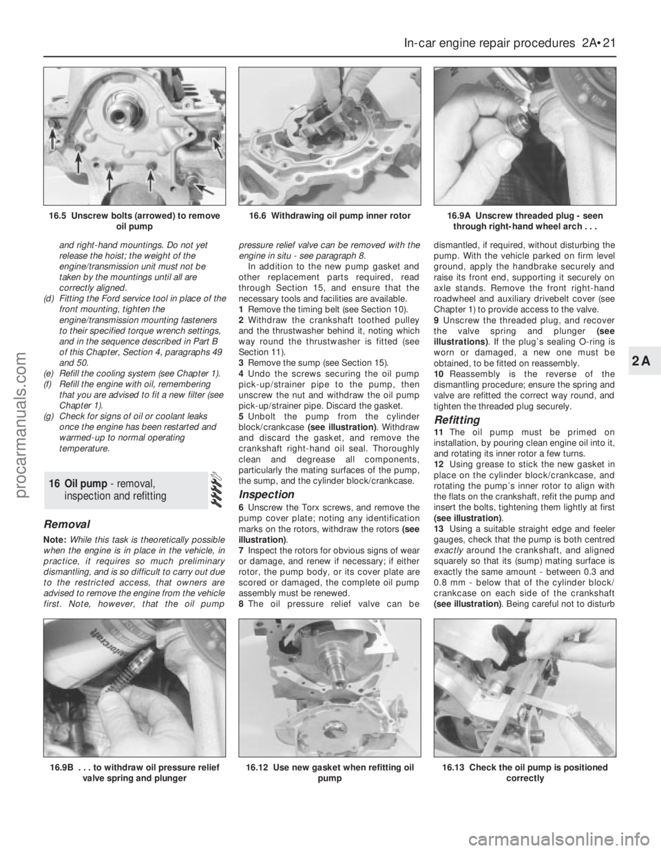
taken by the mountings until all are
correctly aligned.
(d) Fitting the Ford service tool in place of the
front mounting, tighten the
engine/transmission mounting fasteners
to their specified torque wrench settings,
and in the sequence described in Part B
of this Chapter, Section 4, paragraphs 49
and 50.
(e) Refill the cooling system (see Chapter 1).
(f) Refill the engine with oil, remembering
that you are advised to fit a new filter (see
Chapter 1).
(g) Check for signs of oil or coolant leaks
once the engine has been restarted and
warmed-up to normal operating
temperature.
Removal
Note:While this task is theoretically possible
when the engine is in place in the vehicle, in
practice, it requires so much preliminary
dismantling, and is so difficult to carry out due
to the restricted access, that owners are
advised to remove the engine from the vehicle
first. Note, however, that the oil pumppressure relief valve can be removed with the
engine in situ - see paragraph 8.
In addition to the new pump gasket and
other replacement parts required, read
through Section 15, and ensure that the
necessary tools and facilities are available.
1Remove the timing belt (see Section 10).
2Withdraw the crankshaft toothed pulley
and the thrustwasher behind it, noting which
way round the thrustwasher is fitted (see
Section 11).
3Remove the sump (see Section 15).
4Undo the screws securing the oil pump
pick-up/strainer pipe to the pump, then
unscrew the nut and withdraw the oil pump
pick-up/strainer pipe. Discard the gasket.
5Unbolt the pump from the cylinder
block/crankcase (see illustration). Withdraw
and discard the gasket, and remove the
crankshaft right-hand oil seal. Thoroughly
clean and degrease all components,
particularly the mating surfaces of the pump,
the sump, and the cylinder block/crankcase.
Inspection
6Unscrew the Torx screws, and remove the
pump cover plate; noting any identification
marks on the rotors, withdraw the rotors (see
illustration).
7Inspect the rotors for obvious signs of wear
or damage, and renew if necessary; if either
rotor, the pump body, or its cover plate are
scored or damaged, the complete oil pump
assembly must be renewed.
8The oil pressure relief valve can bedismantled, if required, without disturbing the
pump. With the vehicle parked on firm level
ground, apply the handbrake securely and
raise its front end, supporting it securely on
axle stands. Remove the front right-hand
roadwheel and auxiliary drivebelt cover (see
Chapter 1) to provide access to the valve.
9Unscrew the threaded plug, and recover
the valve spring and plunger (see
illustrations). If the plug’s sealing O-ring is
worn or damaged, a new one must be
obtained, to be fitted on reassembly.
10Reassembly is the reverse of the
dismantling procedure; ensure the spring and
valve are refitted the correct way round, and
tighten the threaded plug securely.
Refitting
11The oil pump must be primed on
installation, by pouring clean engine oil into it,
and rotating its inner rotor a few turns.
12Using grease to stick the new gasket in
place on the cylinder block/crankcase, and
rotating the pump’s inner rotor to align with
the flats on the crankshaft, refit the pump and
insert the bolts, tightening them lightly at first
(see illustration).
13Using a suitable straight edge and feeler
gauges, check that the pump is both centred
exactlyaround the crankshaft, and aligned
squarely so that its (sump) mating surface is
exactly the same amount - between 0.3 and
0.8 mm - below that of the cylinder block/
crankcase on each side of the crankshaft
(see illustration). Being careful not to disturb
16 Oil pump - removal,
inspection and refitting
In-car engine repair procedures 2A•21
2A
16.9B . . . to withdraw oil pressure relief
valve spring and plunger16.12 Use new gasket when refitting oil
pump16.13 Check the oil pump is positioned
correctly
16.5 Unscrew bolts (arrowed) to remove
oil pump16.6 Withdrawing oil pump inner rotor16.9A Unscrew threaded plug - seen
through right-hand wheel arch . . .
procarmanuals.com
Page 63 of 279
3Clean the seal housing and crankshaft,
polishing off any burrs or raised edges, which
may have caused the seal to fail in the first
place.
4Refit the oil pump (see Section 16). Grease
the lips and periphery of the new seal, to ease
installation.
5To fit a new seal, Ford recommend the use
of their service tool 21-093A, with the
crankshaft pulley bolt, to draw the seal into
place; an alternative can be arranged using a
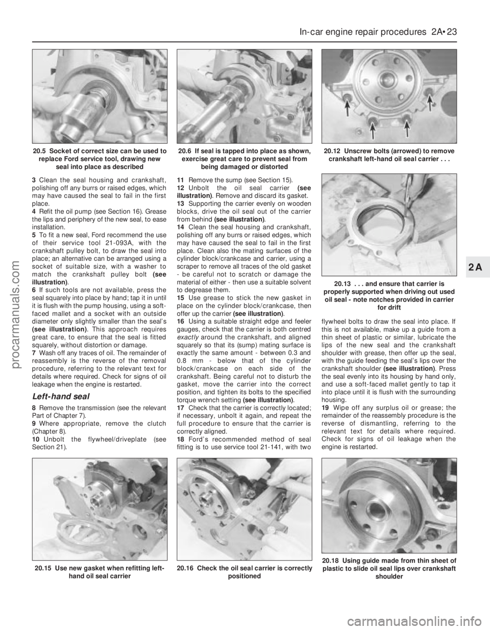
socket of suitable size, with a washer to
match the crankshaft pulley bolt (see
illustration).
6If such tools are not available, press the
seal squarely into place by hand; tap it in until
it is flush with the pump housing, using a soft-
faced mallet and a socket with an outside
diameter only slightly smaller than the seal’s
(see illustration). This approach requires
great care, to ensure that the seal is fitted
squarely, without distortion or damage.
7Wash off any traces of oil. The remainder of
reassembly is the reverse of the removal
procedure, referring to the relevant text for
details where required. Check for signs of oil
leakage when the engine is restarted.
Left-hand seal
8Remove the transmission (see the relevant
Part of Chapter 7).
9Where appropriate, remove the clutch
(Chapter 8).
10Unbolt the flywheel/driveplate (see
Section 21).11Remove the sump (see Section 15).
12Unbolt the oil seal carrier (see
illustration). Remove and discard its gasket.
13Supporting the carrier evenly on wooden
blocks, drive the oil seal out of the carrier
from behind (see illustration).
14Clean the seal housing and crankshaft,
polishing off any burrs or raised edges, which
may have caused the seal to fail in the first
place. Clean also the mating surfaces of the
cylinder block/crankcase and carrier, using a
scraper to remove all traces of the old gasket
- be careful not to scratch or damage the
material of either - then use a suitable solvent
to degrease them.
15Use grease to stick the new gasket in
place on the cylinder block/crankcase, then
offer up the carrier (see illustration).
16Using a suitable straight edge and feeler
gauges, check that the carrier is both centred
exactlyaround the crankshaft, and aligned
squarely so that its (sump) mating surface is
exactly the same amount - between 0.3 and
0.8 mm - below that of the cylinder
block/crankcase on each side of the
crankshaft. Being careful not to disturb the
gasket, move the carrier into the correct
position, and tighten its bolts to the specified
torque wrench setting (see illustration).
17Check that the carrier is correctly located;
if necessary, unbolt it again, and repeat the
full procedure to ensure that the carrier is
correctly aligned.
18Ford’s recommended method of seal
fitting is to use service tool 21-141, with twoflywheel bolts to draw the seal into place. If
this is not available, make up a guide from a
thin sheet of plastic or similar, lubricate the
lips of the new seal and the crankshaft
shoulder with grease, then offer up the seal,
with the guide feeding the seal’s lips over the
crankshaft shoulder (see illustration). Press
the seal evenly into its housing by hand only,
and use a soft-faced mallet gently to tap it
into place until it is flush with the surrounding
housing.
19Wipe off any surplus oil or grease; the
remainder of the reassembly procedure is the
reverse of dismantling, referring to the
relevant text for details where required.
Check for signs of oil leakage when the
engine is restarted.
In-car engine repair procedures 2A•23
2A
20.15 Use new gasket when refitting left-
hand oil seal carrier20.16 Check the oil seal carrier is correctly
positioned20.18 Using guide made from thin sheet of
plastic to slide oil seal lips over crankshaft
shoulder
20.5 Socket of correct size can be used to
replace Ford service tool, drawing new
seal into place as described20.6 If seal is tapped into place as shown,
exercise great care to prevent seal from
being damaged or distorted20.12 Unscrew bolts (arrowed) to remove
crankshaft left-hand oil seal carrier . . .
20.13 . . . and ensure that carrier is
properly supported when driving out used
oil seal - note notches provided in carrier
for drift
procarmanuals.com
Page 64 of 279
Removal
1Remove the transmission (see the relevant
Part of Chapter 7). Now is a good time to
check components such as oil seals and
renew them if necessary.
2Where appropriate, remove the clutch
(Chapter 8). Now is a good time to check or
renew the clutch components and pilot
bearing.
3Use a centre-punch or paint to make
alignment marks on the flywheel/driveplate
and crankshaft, to ensure correct alignment
during refitting.
4Prevent the flywheel/driveplate from
turning by locking the ring gear teeth, or by
bolting a strap between the flywheel/
driveplate and the cylinder block/
crankcase. Slacken the bolts evenly until all
are free.
5Remove each bolt in turn, and ensure that
new replacements are obtained for
reassembly; these bolts are subjected to
severe stresses, and so must be renewed,
regardless of their apparent condition,
whenever they are disturbed.
6Noting the reinforcing plate (automatic
transmission-equipped models only),
withdraw the flywheel/driveplate; do not drop
it - it is very heavy.
Inspection
7Clean the flywheel/driveplate to remove
grease and oil. Inspect the surface for cracks,
rivet grooves, burned areas and score marks.
Light scoring can be removed with emery
cloth. Check for cracked and broken ring gear
teeth. Lay the flywheel/driveplate on a flat
surface, and use a straight edge to check for
warpage.
8Clean and inspect the mating surfaces of
the flywheel/driveplate and the crankshaft. If
the crankshaft left-hand seal is leaking, renew
it (see Section 20) before refitting the
flywheel/driveplate.
9While the flywheel/driveplate is removed,clean carefully its inboard (right-hand) face,
particularly the recesses which serve as the
reference points for the crankshaft
speed/position sensor. Clean the sensor’s tip,
and check that the sensor is securely
fastened.
Refitting
10On refitting, ensure that the
engine/transmission adaptor plate is in place
(where necessary), then fit the
flywheel/driveplate to the crankshaft so that
all bolt holes align - it will fit only one way -
check this using the marks made on removal.
Do not forget the reinforcing plate (where
fitted).
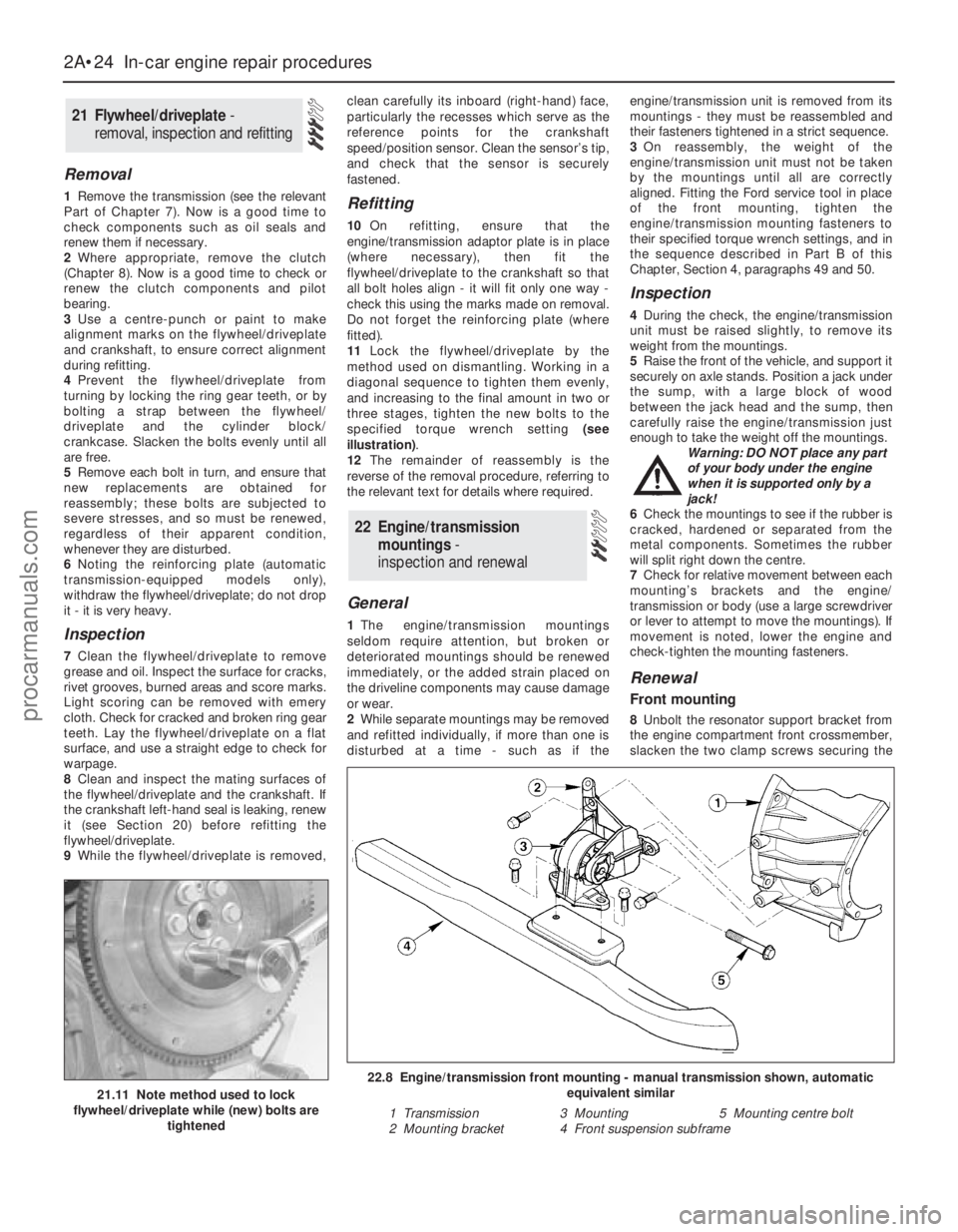
11Lock the flywheel/driveplate by the
method used on dismantling. Working in a
diagonal sequence to tighten them evenly,
and increasing to the final amount in two or
three stages, tighten the new bolts to the
specified torque wrench setting (see
illustration).
12The remainder of reassembly is the
reverse of the removal procedure, referring to
the relevant text for details where required.
General
1The engine/transmission mountings
seldom require attention, but broken or
deteriorated mountings should be renewed
immediately, or the added strain placed on
the driveline components may cause damage
or wear.
2While separate mountings may be removed
and refitted individually, if more than one is
disturbed at a time - such as if theengine/transmission unit is removed from its
mountings - they must be reassembled and
their fasteners tightened in a strict sequence.
3On reassembly, the weight of the
engine/transmission unit must not be taken
by the mountings until all are correctly
aligned. Fitting the Ford service tool in place
of the front mounting, tighten the
engine/transmission mounting fasteners to
their specified torque wrench settings, and in
the sequence described in Part B of this
Chapter, Section 4, paragraphs 49 and 50.
Inspection
4During the check, the engine/transmission
unit must be raised slightly, to remove its
weight from the mountings.
5Raise the front of the vehicle, and support it
securely on axle stands. Position a jack under
the sump, with a large block of wood
between the jack head and the sump, then
carefully raise the engine/transmission just
enough to take the weight off the mountings.
Warning: DO NOT place any part
of your body under the engine
when it is supported only by a
jack!
6Check the mountings to see if the rubber is
cracked, hardened or separated from the
metal components. Sometimes the rubber
will split right down the centre.
7Check for relative movement between each
mounting’s brackets and the engine/
transmission or body (use a large screwdriver
or lever to attempt to move the mountings). If
movement is noted, lower the engine and
check-tighten the mounting fasteners.
Renewal
Front mounting
8Unbolt the resonator support bracket from
the engine compartment front crossmember,
slacken the two clamp screws securing the
22 Engine/transmission
mountings -
inspection and renewal
21 Flywheel/driveplate -
removal, inspection and refitting
2A•24 In-car engine repair procedures
21.11 Note method used to lock
flywheel/driveplate while (new) bolts are
tightened
22.8 Engine/transmission front mounting - manual transmission shown, automatic
equivalent similar
1 Transmission 3 Mounting 5 Mounting centre bolt
2 Mounting bracket 4 Front suspension subframe
procarmanuals.com
Page 80 of 279
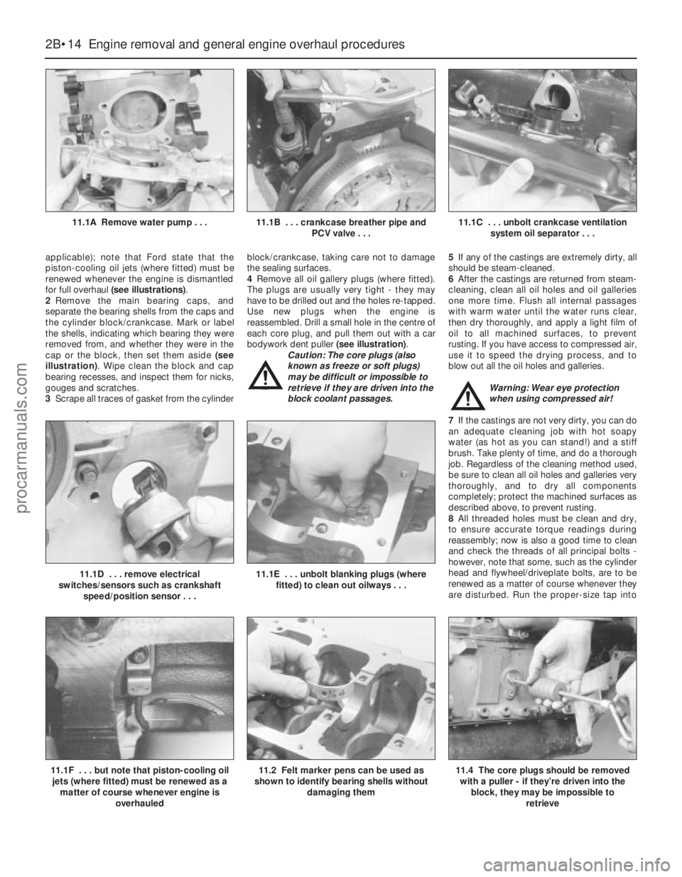
applicable); note that Ford state that the
piston-cooling oil jets (where fitted) must be
renewed whenever the engine is dismantled
for full overhaul (see illustrations).
2Remove the main bearing caps, and
separate the bearing shells from the caps and
the cylinder block/crankcase. Mark or label
the shells, indicating which bearing they were
removed from, and whether they were in the
cap or the block, then set them aside (see
illustration). Wipe clean the block and cap
bearing recesses, and inspect them for nicks,
gouges and scratches.
3Scrape all traces of gasket from the cylinderblock/crankcase, taking care not to damage
the sealing surfaces.
4Remove all oil gallery plugs (where fitted).
The plugs are usually very tight - they may
have to be drilled out and the holes re-tapped.
Use new plugs when the engine is
reassembled. Drill a small hole in the centre of
each core plug, and pull them out with a car
bodywork dent puller (see illustration).
Caution: The core plugs (also
known as freeze or soft plugs)
may be difficult or impossible to
retrieve if they are driven into the
block coolant passages.5If any of the castings are extremely dirty, all
should be steam-cleaned.
6After the castings are returned from steam-
cleaning, clean all oil holes and oil galleries
one more time. Flush all internal passages
with warm water until the water runs clear,
then dry thoroughly, and apply a light film of
oil to all machined surfaces, to prevent
rusting. If you have access to compressed air,
use it to speed the drying process, and to
blow out all the oil holes and galleries.
Warning: Wear eye protection
when using compressed air!
7If the castings are not very dirty, you can do
an adequate cleaning job with hot soapy
water (as hot as you can stand!) and a stiff
brush. Take plenty of time, and do a thorough
job. Regardless of the cleaning method used,
be sure to clean all oil holes and galleries very
thoroughly, and to dry all components
completely; protect the machined surfaces as
described above, to prevent rusting.
8All threaded holes must be clean and dry,
to ensure accurate torque readings during
reassembly; now is also a good time to clean
and check the threads of all principal bolts -
however, note that some, such as the cylinder
head and flywheel/driveplate bolts, are to be
renewed as a matter of course whenever they
are disturbed. Run the proper-size tap into
2B•14 Engine removal and general engine overhaul procedures
11.1A Remove water pump . . .11.1B . . . crankcase breather pipe and
PCV valve . . .11.1C . . . unbolt crankcase ventilation
system oil separator . . .
11.1F . . . but note that piston-cooling oil
jets (where fitted) must be renewed as a
matter of course whenever engine is
overhauled11.2 Felt marker pens can be used as
shown to identify bearing shells without
damaging them
11.1D . . . remove electrical
switches/sensors such as crankshaft
speed/position sensor . . .11.1E . . . unbolt blanking plugs (where
fitted) to clean out oilways . . .
11.4 The core plugs should be removed
with a puller - if they’re driven into the
block, they may be impossible to
retrieve
procarmanuals.com
Page 116 of 279
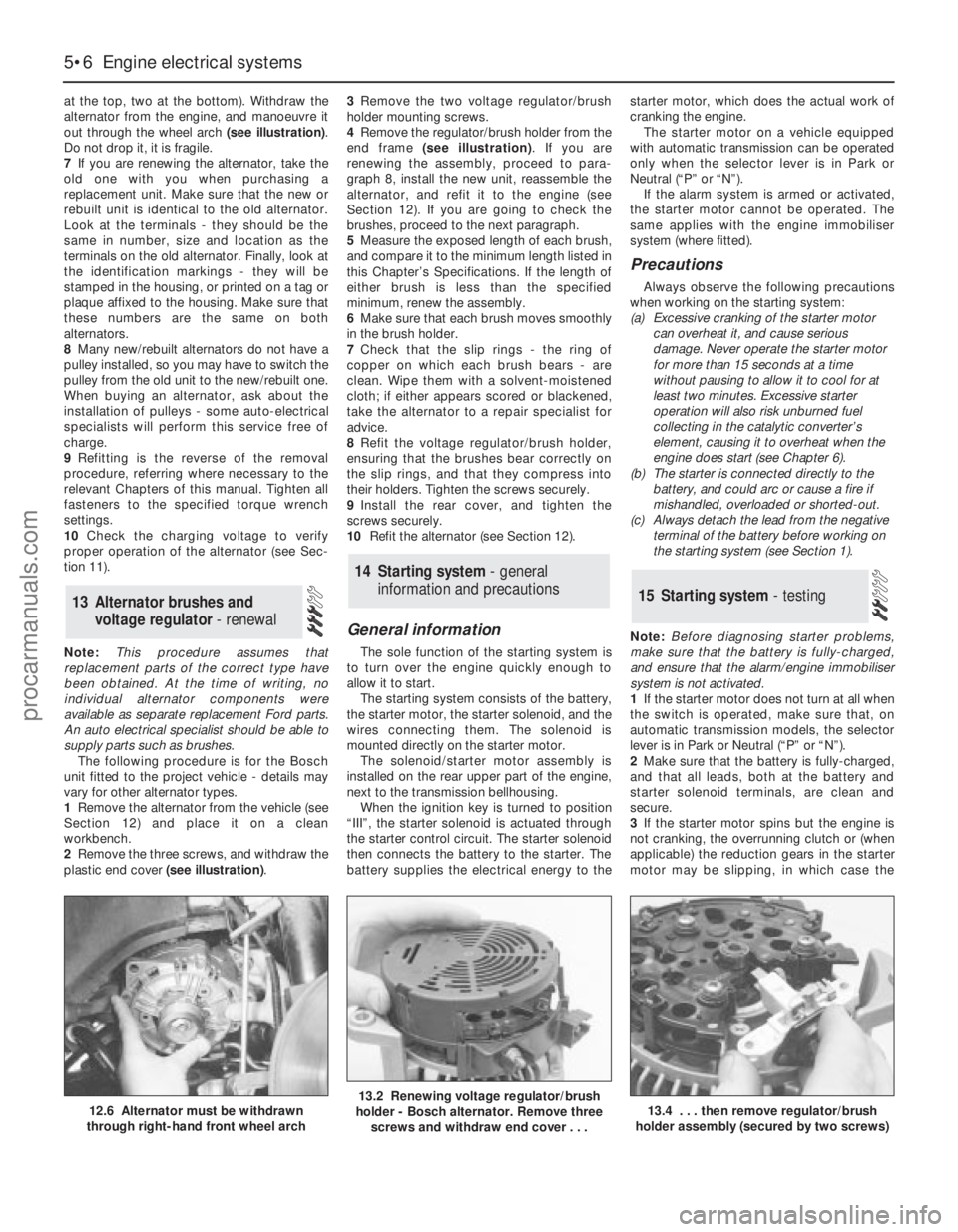
at the top, two at the bottom). Withdraw the
alternator from the engine, and manoeuvre it
out through the wheel arch (see illustration).
Do not drop it, it is fragile.
7If you are renewing the alternator, take the
old one with you when purchasing a
replacement unit. Make sure that the new or
rebuilt unit is identical to the old alternator.
Look at the terminals - they should be the
same in number, size and location as the
terminals on the old alternator. Finally, look at
the identification markings - they will be
stamped in the housing, or printed on a tag or
plaque affixed to the housing. Make sure that
these numbers are the same on both
alternators.
8Many new/rebuilt alternators do not have a
pulley installed, so you may have to switch the
pulley from the old unit to the new/rebuilt one.
When buying an alternator, ask about the
installation of pulleys - some auto-electrical
specialists will perform this service free of
charge.
9Refitting is the reverse of the removal
procedure, referring where necessary to the
relevant Chapters of this manual. Tighten all
fasteners to the specified torque wrench
settings.
10Check the charging voltage to verify
proper operation of the alternator (see Sec-
tion 11).
Note:This procedure assumes that
replacement parts of the correct type have
been obtained. At the time of writing, no
individual alternator components were
available as separate replacement Ford parts.
An auto electrical specialist should be able to
supply parts such as brushes.
The following procedure is for the Bosch
unit fitted to the project vehicle - details may
vary for other alternator types.
1Remove the alternator from the vehicle (see
Section 12) and place it on a clean
workbench.
2Remove the three screws, and withdraw the
plastic end cover (see illustration).3Remove the two voltage regulator/brush
holder mounting screws.
4Remove the regulator/brush holder from the
end frame (see illustration). If you are
renewing the assembly, proceed to para-
graph 8, install the new unit, reassemble the
alternator, and refit it to the engine (see
Section 12). If you are going to check the
brushes, proceed to the next paragraph.
5Measure the exposed length of each brush,
and compare it to the minimum length listed in
this Chapter’s Specifications. If the length of
either brush is less than the specified
minimum, renew the assembly.
6Make sure that each brush moves smoothly
in the brush holder.
7Check that the slip rings - the ring of
copper on which each brush bears - are
clean. Wipe them with a solvent-moistened
cloth; if either appears scored or blackened,
take the alternator to a repair specialist for
advice.
8Refit the voltage regulator/brush holder,
ensuring that the brushes bear correctly on
the slip rings, and that they compress into
their holders. Tighten the screws securely.
9Install the rear cover, and tighten the
screws securely.
10Refit the alternator (see Section 12).
General information
The sole function of the starting system is
to turn over the engine quickly enough to
allow it to start.
The starting system consists of the battery,
the starter motor, the starter solenoid, and the
wires connecting them. The solenoid is
mounted directly on the starter motor.
The solenoid/starter motor assembly is
installed on the rear upper part of the engine,
next to the transmission bellhousing.
When the ignition key is turned to position
“III”, the starter solenoid is actuated through
the starter control circuit. The starter solenoid
then connects the battery to the starter. The
battery supplies the electrical energy to thestarter motor, which does the actual work of
cranking the engine.
The starter motor on a vehicle equipped
with automatic transmission can be operated
only when the selector lever is in Park or
Neutral (“P” or “N”).
If the alarm system is armed or activated,
the starter motor cannot be operated. The
same applies with the engine immobiliser
system (where fitted).
Precautions
Always observe the following precautions
when working on the starting system:
(a) Excessive cranking of the starter motor
can overheat it, and cause serious
damage. Never operate the starter motor
for more than 15 seconds at a time
without pausing to allow it to cool for at
least two minutes. Excessive starter
operation will also risk unburned fuel
collecting in the catalytic converter’s
element, causing it to overheat when the
engine does start (see Chapter 6).
(b) The starter is connected directly to the
battery, and could arc or cause a fire if
mishandled, overloaded or shorted-out.
(c) Always detach the lead from the negative
terminal of the battery before working on
the starting system (see Section 1).
Note:Before diagnosing starter problems,
make sure that the battery is fully-charged,
and ensure that the alarm/engine immobiliser
system is not activated.
1If the starter motor does not turn at all when
the switch is operated, make sure that, on
automatic transmission models, the selector
lever is in Park or Neutral (“P” or “N”).
2Make sure that the battery is fully-charged,
and that all leads, both at the battery and
starter solenoid terminals, are clean and
secure.
3If the starter motor spins but the engine is
not cranking, the overrunning clutch or (when
applicable) the reduction gears in the starter
motor may be slipping, in which case the
15 Starting system - testing
14 Starting system - general
information and precautions
13 Alternator brushes and
voltage regulator - renewal
5•6 Engine electrical systems
12.6 Alternator must be withdrawn
through right-hand front wheel arch13.2 Renewing voltage regulator/brush
holder - Bosch alternator. Remove three
screws and withdraw end cover . . .13.4 . . . then remove regulator/brush
holder assembly (secured by two screws)
procarmanuals.com
Page 117 of 279
starter motor must be overhauled or renewed.
(Other possibilities are that the starter motor
mounting bolts are very loose, or that teeth
are missing from the flywheel/driveplate ring
gear.)
4If, when the switch is actuated, the starter
motor does not operate at all but the solenoid
clicks, then the problem lies with either the
battery, the main solenoid contacts, or the
starter motor itself (or the engine is seized).
5If the solenoid plunger cannot be heard to
click when the switch is actuated, the battery
is faulty, there is a fault in the circuit, or the
solenoid itself is defective.
6To check the solenoid, connect a fused
jumper lead between the battery (+) and the
ignition switch terminal (the small terminal) on
the solenoid. If the starter motor now
operates, the solenoid is OK, and the problem
is in the ignition switch, selector lever position
sensor (automatic transmission) or in the
wiring.
7If the starter motor still does not operate,
remove it (see Section 16). The brushes and
commutator may be checked (see Sec-
tion 17), but if the fault persists, the motor
should be renewed, or taken to an auto-
electrician for testing and repair.
8If the starter motor cranks the engine at anabnormally-slow speed, first make sure that
the battery is charged, and that all terminal
connections are tight. If the engine is partially
seized, or has the wrong viscosity oil in it, it
will crank slowly.
9Run the engine until normal operating
temperature is reached, then switch off and
disable the ignition system by unplugging the
ignition coil’s electrical connector; remove
fuse 14 to disconnect the fuel pump.
10Connect a voltmeter positive lead to the
battery positive terminal, and connect the
negative lead to the negative terminal.
11Crank the engine, and take the voltmeter
readings as soon as a steady figure is
indicated. Do not allow the starter motor to
turn for more than 15 seconds at a time. A
reading of 10.5 volts or more, with the starter
motor turning at normal cranking speed, is
normal. If the reading is 10.5 volts or more but
the cranking speed is slow, the solenoid
contacts are burned, the motor is faulty, or
there is a bad connection. If the reading is less
than 10.5 volts and the cranking speed is
slow, the starter motor is faulty or there is a
problem with the battery.1Disconnect the battery negative (earth) lead
- see Section 1.
2Remove the air mass meter and resonator -
refer to Chapter 4.
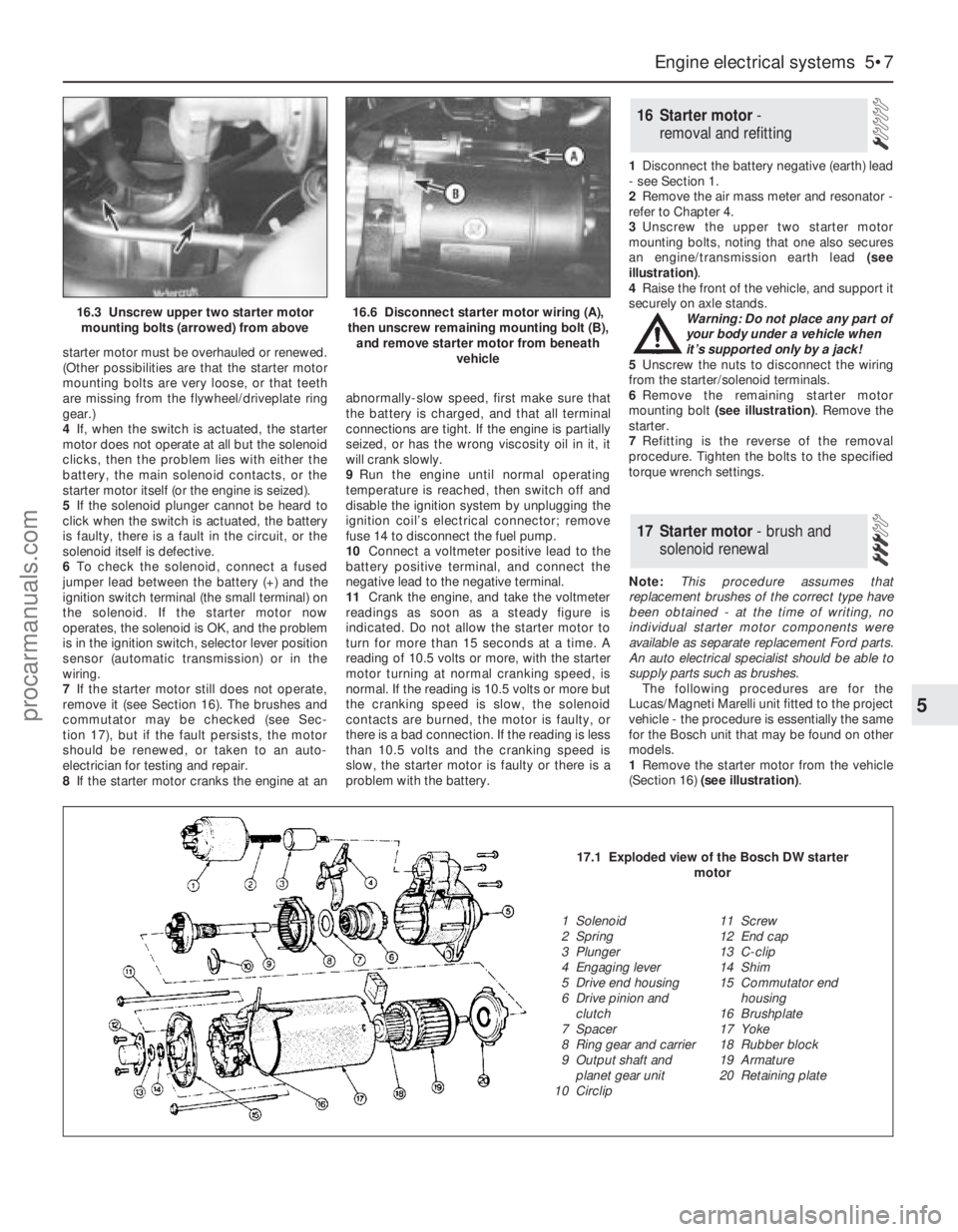
3Unscrew the upper two starter motor
mounting bolts, noting that one also secures
an engine/transmission earth lead (see
illustration).
4Raise the front of the vehicle, and support it
securely on axle stands.
Warning: Do not place any part of
your body under a vehicle when
it’s supported only by a jack!
5Unscrew the nuts to disconnect the wiring
from the starter/solenoid terminals.
6Remove the remaining starter motor
mounting bolt (see illustration). Remove the
starter.
7Refitting is the reverse of the removal
procedure. Tighten the bolts to the specified
torque wrench settings.
Note:This procedure assumes that
replacement brushes of the correct type have
been obtained - at the time of writing, no
individual starter motor components were
available as separate replacement Ford parts.
An auto electrical specialist should be able to
supply parts such as brushes.
The following procedures are for the
Lucas/Magneti Marelli unit fitted to the project
vehicle - the procedure is essentially the same
for the Bosch unit that may be found on other
models.
1Remove the starter motor from the vehicle
(Section 16) (see illustration).
17 Starter motor- brush and
solenoid renewal
16 Starter motor -
removal and refitting
Engine electrical systems 5•7
5
16.3 Unscrew upper two starter motor
mounting bolts (arrowed) from above16.6 Disconnect starter motor wiring (A),
then unscrew remaining mounting bolt (B),
and remove starter motor from beneath
vehicle
17.1 Exploded view of the Bosch DW starter
motor
1 Solenoid
2 Spring
3 Plunger
4 Engaging lever
5 Drive end housing
6 Drive pinion and
clutch
7 Spacer
8 Ring gear and carrier
9 Output shaft and
planet gear unit
10 Circlip11 Screw
12 End cap
13 C-clip
14 Shim
15 Commutator end
housing
16 Brushplate
17 Yoke
18 Rubber block
19 Armature
20 Retaining plate
procarmanuals.com
Page 120 of 279
Torque wrench settingsNm lbf ft
Front caliper bracket . . . . . . . . . . . . . . . . . . . . . . . . . . . . . . . . . . . . . . . . 120 89
Rear caliper bracket . . . . . . . . . . . . . . . . . . . . . . . . . . . . . . . . . . . . . . . . 59 44
Front caliper guide bolts . . . . . . . . . . . . . . . . . . . . . . . . . . . . . . . . . . . . . 28 21
Rear caliper guide bolts . . . . . . . . . . . . . . . . . . . . . . . . . . . . . . . . . . . . . 41 30
Rear drum brake backplate . . . . . . . . . . . . . . . . . . . . . . . . . . . . . . . . . . . 50 37
Vacuum servo unit . . . . . . . . . . . . . . . . . . . . . . . . . . . . . . . . . . . . . . . . . 40 30
Master cylinder . . . . . . . . . . . . . . . . . . . . . . . . . . . . . . . . . . . . . . . . . . . . 23 17
ABS hydraulic unit to bracket . . . . . . . . . . . . . . . . . . . . . . . . . . . . . . . . . 20 15
Roadwheel nuts . . . . . . . . . . . . . . . . . . . . . . . . . . . . . . . . . . . . . . . . . . . 85 63
9•2 Braking system
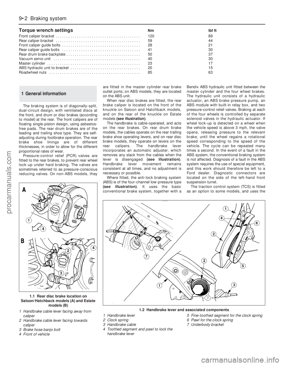
1.2 Handbrake lever and associated components
1 Handbrake lever
2 Clock spring
3 Handbrake cable
4 Toothed segment and pawl to lock the
handbrake lever5 Fine-toothed segment for the clock spring
6 Pawl for the clock spring
7 Underbody bracket
The braking system is of diagonally-split,
dual-circuit design, with ventilated discs at
the front, and drum or disc brakes (according
to model) at the rear. The front calipers are of
floating single-piston design, using asbestos-
free pads. The rear drum brakes are of the
leading and trailing shoe type. They are self-
adjusting during footbrake operation. The rear
brake shoe linings are of different
thicknesses, in order to allow for the different
proportional rates of wear.
Pressure-control relief (PCR) valves are
fitted to the rear brakes, to prevent rear wheel
lock-up under hard braking. The valves are
sometimes referred to as pressure-conscious
reducing valves. On non-ABS models, theyare fitted in the master cylinder rear brake
outlet ports; on ABS models, they are located
on the ABS unit.
When rear disc brakes are fitted, the rear
brake caliper is located on the front of the
knuckle on Saloon and Hatchback models,
and on the rear of the knuckle on Estate
models (see illustration).
The handbrake is cable-operated, and acts
on the rear brakes. On rear drum brake
models, the cables operate on the rear trailing
brake shoe operating levers, and on rear disc
brake models, they operate on levers on the
rear calipers. The handbrake lever
incorporates an automatic adjuster, which
removes any slack from the cables when the
lever is disengaged (see illustration).
Handbrake lever movement remains
consistent at all times, and no adjustment is
necessary or possible.
Where fitted, the anti-lock braking system
(ABS) is of the four-channel low-pressure type
(see illustration). It uses the basic
conventional brake system, together with aBendix ABS hydraulic unit fitted between the
master cylinder and the four wheel brakes.
The hydraulic unit consists of a hydraulic
actuator, an ABS brake pressure pump, an
ABS module with built-in relay box, and two
pressure-control relief valves. Braking at each
of the four wheels is controlled by separate
solenoid valves in the hydraulic actuator. If
wheel lock-up is detected on a wheel when
the vehicle speed is above 3 mph, the valve
opens, releasing pressure to the relevant
brake, until the wheel regains a rotational
speed corresponding to the speed of the
vehicle. The cycle can be repeated many
times a second. In the event of a fault in the
ABS system, the conventional braking system
is not affected. Diagnosis of a fault in the ABS
system requires the use of special equipment,
and this work should therefore be left to a
Ford dealer. Diagnostic connectors are
located on the side of the left-hand front
suspension turret.
The traction control system (TCS) is fitted
as an option to some models, and uses the
1 General information
1.1 Rear disc brake location on
Saloon/Hatchback models (A) and Estate
models (B)
1 Handbrake cable lever facing away from
caliper
2 Handbrake cable lever facing towards
caliper
3 Brake hose banjo bolt
4 Front of vehicle
procarmanuals.com
Page 121 of 279
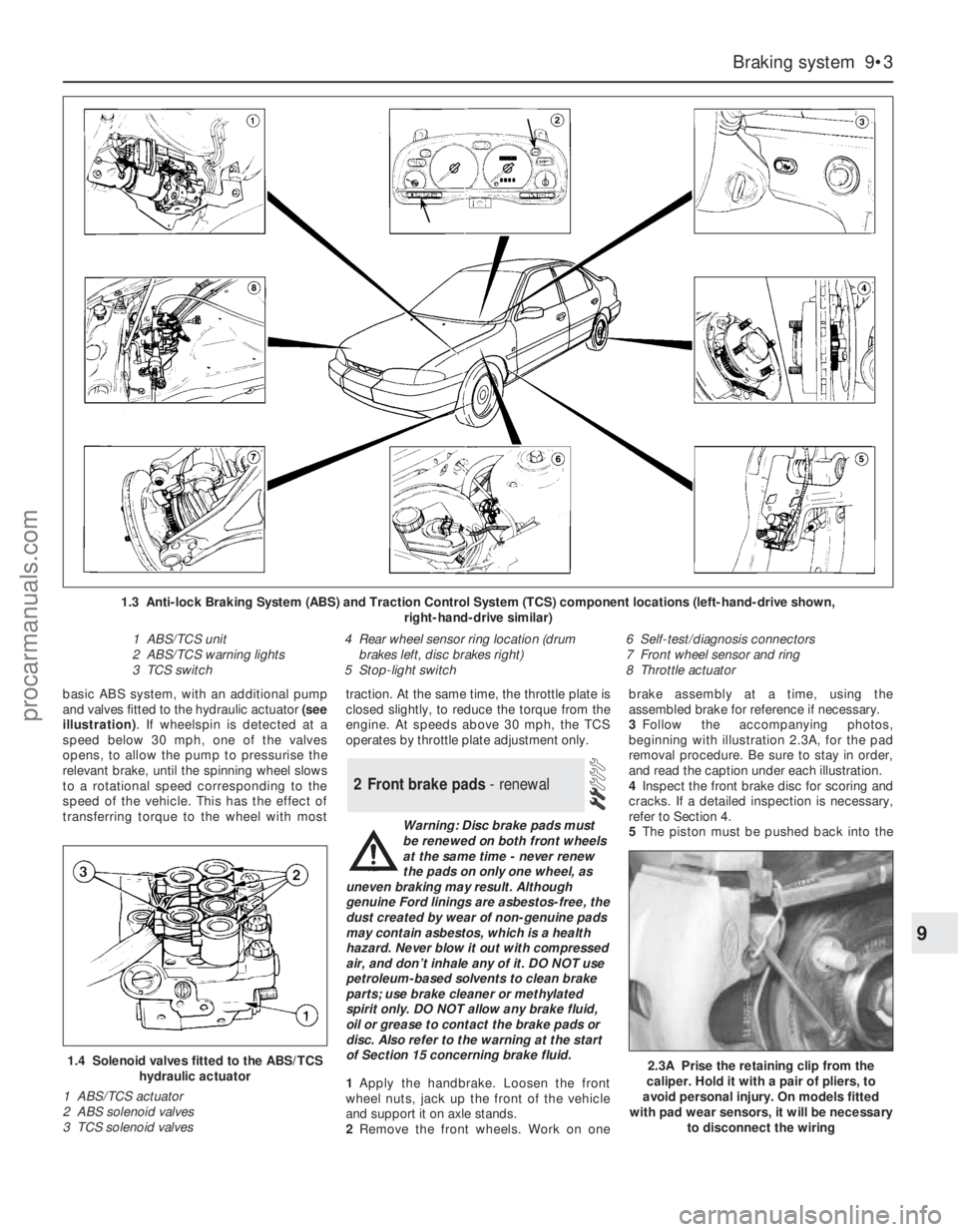
basic ABS system, with an additional pump
and valves fitted to the hydraulic actuator (see
illustration). If wheelspin is detected at a
speed below 30 mph, one of the valves
opens, to allow the pump to pressurise the
relevant brake, until the spinning wheel slows
to a rotational speed corresponding to the
speed of the vehicle. This has the effect of
transferring torque to the wheel with mosttraction. At the same time, the throttle plate is
closed slightly, to reduce the torque from the
engine. At speeds above 30 mph, the TCS
operates by throttle plate adjustment only.
Warning: Disc brake pads must
be renewed on both front wheels
at the same time - never renew
the pads on only one wheel, as
uneven braking may result. Although
genuine Ford linings are asbestos-free, the
dust created by wear of non-genuine pads
may contain asbestos, which is a health
hazard. Never blow it out with compressed
air, and don’t inhale any of it. DO NOT use
petroleum-based solvents to clean brake
parts; use brake cleaner or methylated
spirit only. DO NOT allow any brake fluid,
oil or grease to contact the brake pads or
disc. Also refer to the warning at the start
of Section 15 concerning brake fluid.
1Apply the handbrake. Loosen the front
wheel nuts, jack up the front of the vehicle
and support it on axle stands.
2Remove the front wheels. Work on onebrake assembly at a time, using the
assembled brake for reference if necessary.
3Follow the accompanying photos,
beginning with illustration 2.3A, for the pad
removal procedure. Be sure to stay in order,
and read the caption under each illustration.
4Inspect the front brake disc for scoring and
cracks. If a detailed inspection is necessary,
refer to Section 4.
5The piston must be pushed back into the
2 Front brake pads - renewal
Braking system 9•3
9
1.4 Solenoid valves fitted to the ABS/TCS
hydraulic actuator
1 ABS/TCS actuator
2 ABS solenoid valves
3 TCS solenoid valves
1.3 Anti-lock Braking System (ABS) and Traction Control System (TCS) component locations (left-hand-drive shown,
right-hand-drive similar)
1 ABS/TCS unit
2 ABS/TCS warning lights
3 TCS switch4 Rear wheel sensor ring location (drum
brakes left, disc brakes right)
5 Stop-light switch6 Self-test/diagnosis connectors
7 Front wheel sensor and ring
8 Throttle actuator
2.3A Prise the retaining clip from the
caliper. Hold it with a pair of pliers, to
avoid personal injury. On models fitted
with pad wear sensors, it will be necessary
to disconnect the wiring
procarmanuals.com